fasee ullah, abdul hanan abdullah, omprakash kaiwartya
TRANSCRIPT
computers
Article
Traffic Priority-Aware Adaptive Slot Allocation forMedium Access Control Protocol in Wireless BodyArea Network
Fasee Ullah, Abdul Hanan Abdullah, Omprakash Kaiwartya * and Marina Md Arshad
Faculty of Computing, Universiti Teknologi Malaysia, Skudai 81310, Johor Bahru, Malaysia;[email protected] (F.U.); [email protected] (A.H.A.); [email protected] (M.M.A.)* Correspondence: [email protected]; Tel.: +60-111-147-0146
Academic Editor: Subhas Chandra MukhopadhyayReceived: 1 January 2017; Accepted: 14 February 2017; Published: 20 February 2017
Abstract: Biomedical sensors (BMSs) monitor the heterogeneous vital signs of patients.They have diverse Quality of Service (QoS) requirements including reduced collision, delay, loss,and energy consumption in the transmission of data, which are non-constrained, delay-constrained,reliability-constrained, and critical. In this context, this paper proposes a traffic priority-awareadaptive slot allocation-based medium access control (TraySL-MAC) protocol. Firstly, a reducedcontention adaptive slot allocation algorithm is presented to minimize contention rounds. Secondly,a low threshold vital signs criticality-based adaptive slot allocation algorithm is developed for highpriority data. Thirdly, a high threshold vital signs criticality-based adaptive slot allocation algorithm isdesigned for low priority data. Simulations are performed to comparatively evaluate the performanceof the proposed protocol with state-of-the-art MAC protocols. From the analysis of the results, it isevident that the proposed protocol is beneficial in terms of lower packet delivery delay and energyconsumption, and higher throughput in realistic biomedical environments.
Keywords: medium access control protocol; wireless body area networks; wireless sensor networks
1. Introduction
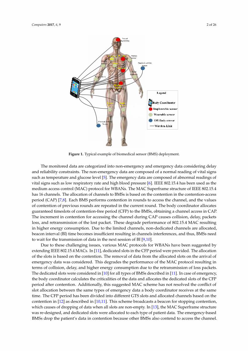
Wireless body area networks (WBANs) have attracted researcher communities due to the growingsignificance of monitoring heterogeneous vital signs in the domain of medical and health-care, sportsand entertainments, and rehabilitation systems. The vital signs include temperature, blood pressure,heartbeat rate, respiration, electrocardiogram (ECG), electroencephalogram (EEG), and glucose level [1].These vital signs are monitored using biomedical sensors (BMSs), which are deployed on the patient’sbody in three methods as shown in Figure 1. The implantation is the first method, which is used todeploy BMSs inside the patient’s body for monitoring internal organs [2]. The second deploymentmethod is wearing BMSs, whereby BMSs are attached to the skin or sewn onto a patient’s shirt.They externally monitor organ conditions, including temperature, blood pressure, and heartbeat [3].In the third method, BMSs are deployed near the patient’s body to monitor body positions, includingsleep duration, arm direction, and handshaking [4]. The monitored sensory data are then transmittedto the body coordinator, and the body coordinator transmits data to the medical doctors for analysisand treatments.
Computers 2017, 6, 9; doi:10.3390/computers6010009 www.mdpi.com/journal/computers
Computers 2017, 6, 9 2 of 26Computers 2017, 6, 9 2 of 26
Figure 1. Typical example of biomedical sensor (BMS) deployment.
The monitored data are categorized into non-emergency and emergency data considering delay and reliability constraints. The non-emergency data are composed of a normal reading of vital signs such as temperature and glucose level [5]. The emergency data are composed of abnormal readings of vital signs such as low respiratory rate and high blood pressure [6]. IEEE 802.15.4 has been used as the medium access control (MAC) protocol for WBANs. The MAC Superframe structure of IEEE 802.15.4 has 16 channels. The allocation of channels to BMSs is based on the contention in the contention-access period (CAP) [7,8]. Each BMS performs contention in rounds to access the channel, and the values of contention of previous rounds are repeated in the current round. The body coordinator allocates guaranteed timeslots of contention-free period (CFP) to the BMSs, obtaining a channel access in CAP. The increment in contention for accessing the channel during CAP causes collision, delay, packets loss, and retransmission of the lost packet. These degrade performance of 802.15.4 MAC resulting in higher energy consumption. Due to the limited channels, non-dedicated channels are allocated, beacon interval (BI) time becomes insufficient resulting in channels interferences, and thus, BMSs need to wait for the transmission of data in the next session of BI [9,10].
Due to these challenging issues, various MAC protocols for WBANs have been suggested by extending IEEE 802.15.4 MACs. In [11], dedicated slots in the CFP period were provided. The allocation of the slots is based on the contention. The removal of data from the allocated slots on the arrival of emergency data was considered. This degrades the performance of the MAC protocol resulting in terms of collision, delay, and higher energy consumption due to the retransmission of loss packets. The dedicated slots were considered in [10] for all types of BMSs described in [11]. In case of emergency, the body coordinator calculates the criticalities of the data and allocates the dedicated slots of the CFP period after contention. Additionally, this suggested MAC scheme has not resolved the conflict of slot allocation between the same types of emergency data a body coordinator receives at the same time. The CFP period has been divided into different GTS slots and allocated channels based on the contention in [12] as described in [10,11]. This scheme broadcasts a beacon for stopping contention, which causes of dropping of data when all slots are non-empty. In [13], the MAC Superframe structure was re-designed, and dedicated slots were allocated to each type of patient data. The emergency-based BMSs drop the patient’s data in contention because other BMSs also contend to access the channel. The same concept of re-designing the MAC Superframe structure was considered in [14]. In emergency situations, other BMSs are informed to stop contention using a flag
Figure 1. Typical example of biomedical sensor (BMS) deployment.
The monitored data are categorized into non-emergency and emergency data considering delayand reliability constraints. The non-emergency data are composed of a normal reading of vital signssuch as temperature and glucose level [5]. The emergency data are composed of abnormal readings ofvital signs such as low respiratory rate and high blood pressure [6]. IEEE 802.15.4 has been used as themedium access control (MAC) protocol for WBANs. The MAC Superframe structure of IEEE 802.15.4has 16 channels. The allocation of channels to BMSs is based on the contention in the contention-accessperiod (CAP) [7,8]. Each BMS performs contention in rounds to access the channel, and the valuesof contention of previous rounds are repeated in the current round. The body coordinator allocatesguaranteed timeslots of contention-free period (CFP) to the BMSs, obtaining a channel access in CAP.The increment in contention for accessing the channel during CAP causes collision, delay, packetsloss, and retransmission of the lost packet. These degrade performance of 802.15.4 MAC resultingin higher energy consumption. Due to the limited channels, non-dedicated channels are allocated,beacon interval (BI) time becomes insufficient resulting in channels interferences, and thus, BMSs needto wait for the transmission of data in the next session of BI [9,10].
Due to these challenging issues, various MAC protocols for WBANs have been suggested byextending IEEE 802.15.4 MACs. In [11], dedicated slots in the CFP period were provided. The allocationof the slots is based on the contention. The removal of data from the allocated slots on the arrival ofemergency data was considered. This degrades the performance of the MAC protocol resulting interms of collision, delay, and higher energy consumption due to the retransmission of loss packets.The dedicated slots were considered in [10] for all types of BMSs described in [11]. In case of emergency,the body coordinator calculates the criticalities of the data and allocates the dedicated slots of the CFPperiod after contention. Additionally, this suggested MAC scheme has not resolved the conflict ofslot allocation between the same types of emergency data a body coordinator receives at the sametime. The CFP period has been divided into different GTS slots and allocated channels based on thecontention in [12] as described in [10,11]. This scheme broadcasts a beacon for stopping contention,which causes of dropping of data when all slots are non-empty. In [13], the MAC Superframe structurewas re-designed, and dedicated slots were allocated to each type of patient data. The emergency-basedBMSs drop the patient’s data in contention because other BMSs also contend to access the channel.
Computers 2017, 6, 9 3 of 26
The same concept of re-designing the MAC Superframe structure was considered in [14]. In emergencysituations, other BMSs are informed to stop contention using a flag value “set”. The dedicated slotswere considered in [15] as used in [10,11]. In contention, the emergency-based BMS uses a slot ofdifferent data when there is a non-empty slot available in the designated slots. This causes data ofother BMSs to drop.
In this context, this paper proposes a traffic priority-aware adaptive slot allocation-based mediumaccess control (TraySL-MAC) protocol, which prioritizes patient data for appropriate slot allocation.Specifically, the contributions of the paper are listed below:
• Firstly, a reduced contention adaptive slot allocation algorithm is presented, to minimizecontention rounds during the transmission of data from BMSs to the body coordinator.
• Secondly, a low threshold vital signs criticality-based adaptive slot allocation algorithm isdeveloped to resolve slot allocation conflicts among high priority data.
• Thirdly, a high threshold vital signs criticality-based adaptive slot allocation algorithm is designedto resolve slot allocation conflicts among low priority data.
• Simulations are performed in realistic biomedical environments, to comparatively evaluate theperformance of the proposed protocol with state-of-the-art MAC protocols.
The rest of this paper is organized as follows. Section 2 reviews related literature on MACprotocols for WNANs focusing on the extensions of IEEE 802.15.4. Section 3 presents the detail of theproposed TraySL-MAC protocol focusing on the network model, super-frame structure, and three slotallocation algorithms. Section 4 discusses comparative performance evaluation considering simulationenvironments and analysis of results, followed by conclusion made in Section 5.
2. Related Works
The channel allocation is the basic requirement to transmit heterogeneous nature of a patient’sdata in WBANs. The MAC Superframe structures of IEEE 802.11 [16] and IEEE 802.15 [17] do notsupport and allocate channels to a patient’s data. IEEE 802.15.4 is suitable for channel allocation forpatient data and thus preferred in WBANs. The features and limitations of 802.15.4 are explored below.
IEEE 802.15.4 classifies the patient’s data into normal, periodic, and emergency data. The normaldata is comprised of a temperature. The periodic data contains the reading of glucose and bloodpressure. The emergency data contains life threatening vital signs information. The Superframestructure of IEEE 802.15.4 MAC [7,8] is comprised of a beacon, CAP, CFP, and a lower power listening(LPL)/inactive period (IP). At the beginning of communication, the body coordinator broadcastsa beacon to all BMSs in the network, which contains information about synchronization, the addressof the body coordinator, and the next announcement of the beacon interval (BI). In synchronization,BMSs transmit the request for channel association and dissociation to the body coordinator. The addressof the body coordinator is broadcasted to BMSs for remembering it as the head/coordinator to allocatechannels and transmit data. The BI is the time period, whereas each BMS contends and transmitssensory data in the specified amount of time. The IP is used to save energy when a BMS is not busyfor transmitting sensory data. In contention, each BMS performs many back-offs and clear channelassessment (CCA) to access the channel [18,19]. The body coordinator allocates channels of the CFPperiod to those BMSs that obtained a channel access in the CAP period [20]. The followings are thelimitations of the Superframe structure of IEEE 802.15.4 MAC [12] as follows:
� IEEE 802.15.4 provides limited 16 (0–15) channels.� All BMSs perform contention and repeats the previous rounds of contention in the current rounds
to access the channel in the CAP period.� Allocation of the CFP channels only to those BMSs that obtained a channel access in the
CAP period.
Computers 2017, 6, 9 4 of 26
� During contention to access the channel, there is no priority-basis slot allocated to emergencydata, and there is no differentiation between normal, periodic, and emergency data to assign thefirst slot based on priority during life critical situations.
� Due to contention, BMSs consume a higher amount of energy and drop patient data by exceedingthe threshold values of contention.
� In TDMA, each BMS transmits sensory data in the fixed length of time and drops data if ithas a large amount of data (frame). For instance, the report of the ECG is comprised of longsensory information.
These limitations severely reduce the performance of the MAC Superframe structure in termsof a higher collision. BMSs retransmit the lost data packets causing a delay with lower reliabilityand a higher amount of energy consumption, which is not tolerable in emergency situations. Due tothese challenges, the Superframe structure of IEEE 802.15.4 MAC has been modified in recent works,which are discussed as follows.
The emergency data (ED), periodic data (PD), and normal data (ND) [21] are considered thepatient’s data, and the allocation of the CAP channel to these data is based on the contention.The proposed MAC Superframe structure of this scheme uses an emergency beacon in emergencysituations for ED data, but the allocation of slots is based on the contention. In addition, this scheme [21]does not resolve the conflict of slot allocation when the body coordinator receives ED data at the sametime. The same contention process of slot allocation is followed in this Preemptive and Non-PreemptiveMAC (PNP-MAC) [11]. However, this PNP-MAC was introduced by allocating dedicated EmergencyData Transfer slots (ETSs) and Data Transfer Slots (DTSs) to a patient’s data. The second limitation ofthis scheme is that it preempts the non-emergency data on the arrival of emergency data from DTSor ETS slots. However, the slot allocation policy based on the contention and preemption of data isthe drawback by reducing the performance of the MAC protocol in terms of a higher collision, delay,retransmission of the lost packets, and high-energy consumption of BMSs.
Similarly, the suggested priority-based load adaptive MAC (PLA-MAC) protocol [10] provides128 channels and categorizes the patient’s data into four classes: critical data packet (CP), reliability datapacket (RP), delay data packet (DP), and ordinary packet (OP). Additionally, PLA-MAC provides thesame dedicated DTS and ETS slots for non-emergency and emergency data, respectively, as mentionedin the PNP-MAC. However, the contention is used to allocate the channel of the CAP period,which greatly reduces the performance of the MAC protocol as aforementioned and consumes a highamount of energy of BMSs. Further, this PLA-MAC uses an equation which decides whether toassign DTS or ETS slots based on the nature of the data when a BMS obtains channel access in theCAP period. Another limitation is the conflict of slot allocation occurs when a body coordinatorreceives data of the same threshold values. The low-delay traffic-adaptive medium access control(LTD-MAC) [12] is the same contention-based channel allocation in that the size of the CFP periodis extended. This scheme also claims that all BMSs contend and transmit data in the same beaconinterval (BI) using BI = 6 and SO = 5, which is not possible for 14 BMSs. Another limitation ofthis LTD-MAC is the stopping contention and transmission of data when all channels are occupied,whereby BMSs drop data. The service differentiation and GTS slot allocation are introduced in theadaptive and real-time GTS allocation (ART-GAS) [22]. The service differentiation is associated withdata-based priority and rate-based priority. However, these introduced processes of slot allocationto BMSs are based on the contention and has the same challenges found in this ART-GAS scheme asaforementioned. This MAC [13] allocates dedicated emergency-TDMA (ETDMA), medical contentionaccess periods (MCAP), normal-TDMA (NTDMA), CAP, and emergency slots (ESs) to emergencyand non-emergency data. The emergency-based BMS drop the patient’s data under two conditions:(1) when they perform the contention to access the channel in the CAP period, but cannot accessthe channel because other BMSs are also contending the same channel; and (2), with failure in (1),these BMSs try an ES by informing the body coordinator with the assistance of an alert signal in whichthe body coordinator receives multiple alert signals from other BMSs and drops the packets of BMSs.

Computers 2017, 6, 9 5 of 26
Clearly, this scheme [13] creates overhead by changing positions of the periods in emergency andcontention, which is not an appropriate solution to allocate slots in this way.
The suggested fuzzy control medium access (FCMA) [23] uses acquisition, fuzzy logic control,and implementation phases. Sensory data of a patient’s are collected and sent to the body coordinatorby using the acquisition phase. Afterwards, the decision of slot allocation is either CAP or CFP periodfollowing the rules in the fuzzy logic control phase, which is based on the data rate and prioritydata. The same contention process is noticed in this FCMA scheme. The priority-based adaptivetimeslot allocation (PTA) [24] classifies the CAP channels into different phases. Each BMS contendsto access and transmit data in the dedicated slots of phases. The contention and limited channel arethe challenges in this PTA scheme as aforementioned. Moreover, the proposed MAC [14] introducesslots: an emergency contention period (ECP), an advertisement beacon (AB), a periodic contentionaccess period (PCAP), a notification beacon (NB), and a data transmission period (DTP) for emergencyand non-emergency data. In emergency situations, the emergency-based BMSs contend to access achannel in the ECP period and the body coordinator informs the whole network about the emergencydata by setting the value of a flag as “set” with the support of an AB message. The patient’s datauses PCAP and DTP periods based on the contention. Additionally, this scheme does not resolvethe conflict of slot allocation between BMSs. This priority-adaptive MAC (PA-MAC) [15] dividesthe CAP channels into four phases. It has the same process of contention-based channel allocation.The emergency data can access all four phases of channels, on-demand data can access Phases 2 to 4,normal data can access Phases 3 and 4; and non-medical data can access only Phase 4. The samecontention process does not allocate dedicated slots to emergency data without contention, as noticedin this scheme, which is a limitation for emergency data. The multi-channel MAC (MC-MAC) [25]introduces flags concept in the contention. The contention permission is broadcasted in a beacon frameto all BMSs whether they can perform contention or they need to wait for the next announcement ofBI. Similarly, this token-based two-round reservation MAC (TTR-MAC) [26] divides the slots of theSuperframe structure into first-round reservation period (FRRP), second-round reservation Period(SRRP), and sleep period (SP). The FRRP contains three-way handshaking in the contention with thebody coordinator. The BMSs need to wait for SRRP if they do not access the channel in the FRRP.Clearly, the existing MAC schemes have not considered the contention-based channel allocation intheir designs. The contention degrades the performance of the MAC protocol, resulting in a highercollision. The BMS retransmits the lost/collided packets, causing delay, lower data reliability, and highenergy consumption. Therefore, there is a need for a MAC protocol that should address the limitationsof the existing MAC schemes.
3. Traffic Priority-Aware Adaptive Slot Allocation for Medium Access Control
In this section, the detail of traffic priority aware slot allocation is proposed, focusing on thenetwork model, the super-frame structure, and three slot allocation algorithms.
3.1. Network Model
The proposed TraySL-MAC provides 128 slots in the Superframe structure, comprised of a beacon(B), a CAP, a notification (N), an on-demand (OD) slot, a non-emergency data transfer slot (NTDS),an emergency beacon for a low threshold value (EB_Low), an emergency beacon for a high thresholdvalue (EB_High), a critical low threshold transfer slot (CLTTS), and a critical high threshold transferslot (CHTTS). For the CAP period, the body coordinator assigns 24 slots and the non-emergency-basedBMSs perform contention to access the channel. The B, N, OD, EB_Low, and EB_High periods occupysingle slot. Similarly, the body coordinator assigns 32 slots to the NDTS period, and 33 slots each to theCLTTS and CHTTS periods. The N, OD, NDTS, EB_Low, CLTTS, EB_High, and CHTTS are groupedin the CFP period. Moreover, it is assumed that several tiny BMSs are installed inside and outside ofa patient’s body to monitor vital signs. Thus, the contributions are as follows:

Computers 2017, 6, 9 6 of 26
i. This study proposes Superframe structure of the TraySL-MAC protocol and provides sufficientchannels by classifying the operating frequency into sub-frequencies.
ii. The sub-frequencies avoid the channel interferences, and BMSs transmit the long report of ECGwith a sufficient time period of BI.
iii. The proposed ReCAL-CSMA/CA mechanism reduces the repetition in rounds of contention ofnon-emergency-based BMSs and does not drop the patient’s data.
iv. Emergency-based BMSs do not contend to access the CAP channel, but they transmitalert signals to the dedicated emergency beacons. For this purpose, this study proposesa delay-aware mechanism, known as VSCAS.
v. The proposed TraySL-MAC protocol and other mechanisms improve throughput and packetdelivery ratio (PDR), and reduces energy consumption and packet delivery delay.
The heterogeneous nature of a patient’s data needs to transmit immediately to the bodycoordinator without collision, delay, packet loss, and minimum energy of consumption of BMSs.Based on these delays and reliability constraints, this paper classifies frequency bands, and patientdata; the working steps of the proposed Superframe structure of the TraySL-MAC, ReCAL-CSMA/CA,and VSCAS schemes.
3.2. Frequency Bands
The operating frequency 2.4 GHz of the PHY layer in IEEE 802.15.4 provides 16 channels [27,28].The challenging issue is that the provided 16 channels are not sufficient for the heterogeneous nature ofa patient’s data to transmit without loss or delay, or consume a minimum energy of BMSs. In this paper,we classify the operating frequency spectrum 2.4 GHz into 16 sub-frequency spectrums: 2401 MHz,2403 MHz, 2405 MHz, . . . , and 2431 MHz, as shown in Figure 2. Each sub-frequency spectrum provideseight channels and the bandwidth of each channel is 9.375 MHz. This higher bandwidth transmitsa larger amount of data within a minimum time period. Further, the channel interferences/overlappingare avoided with the support of a guard band, and its gap between channels is 0.1 MHz. The guardband protects the channels from interference in assisting not to corrupt and collide data [29]. Similarly,the guard band between the main channels is 2.0 GHz. Hence, the proposed Superframe structure ofthe TraySL-MAC is designed with 128 channels.
Computers 2017, 6, 9 6 of 26
iv. Emergency-based BMSs do not contend to access the CAP channel, but they transmit alert signals to the dedicated emergency beacons. For this purpose, this study proposes a delay-aware mechanism, known as VSCAS.
v. The proposed TraySL-MAC protocol and other mechanisms improve throughput and packet delivery ratio (PDR), and reduces energy consumption and packet delivery delay.
The heterogeneous nature of a patient’s data needs to transmit immediately to the body coordinator without collision, delay, packet loss, and minimum energy of consumption of BMSs. Based on these delays and reliability constraints, this paper classifies frequency bands, and patient data; the working steps of the proposed Superframe structure of the TraySL-MAC, ReCAL-CSMA/CA, and VSCAS schemes.
3.2. Frequency Bands
The operating frequency 2.4 GHz of the PHY layer in IEEE 802.15.4 provides 16 channels [27,28]. The challenging issue is that the provided 16 channels are not sufficient for the heterogeneous nature of a patient’s data to transmit without loss or delay, or consume a minimum energy of BMSs. In this paper, we classify the operating frequency spectrum 2.4 GHz into 16 sub-frequency spectrums: 2401 MHz, 2403 MHz, 2405 MHz, …, and 2431 MHz, as shown in Figure 2. Each sub-frequency spectrum provides eight channels and the bandwidth of each channel is 9.375 MHz. This higher bandwidth transmits a larger amount of data within a minimum time period. Further, the channel interferences/overlapping are avoided with the support of a guard band, and its gap between channels is 0.1 MHz. The guard band protects the channels from interference in assisting not to corrupt and collide data [29]. Similarly, the guard band between the main channels is 2.0 GHz. Hence, the proposed Superframe structure of the TraySL-MAC is designed with 128 channels.
Figure 2. The proposed frequency spectrums for the traffic priority-aware adaptive slot allocation-based medium access control (TraySL-MAC).
3.3. Patient’s Traffic Classification
The patient’s data are classified into non-constrained data (NCD), delay-constrained data (DCD), reliability-constrained data (RCD), and critical data (CD) as described in [30]. These classification of a patient’s data assist to fulfill the requirements for real time healthcare applications. The NCD does not impose delay or constrain reliability, and is comprised of physiological vital signs, i.e., temperature and glucose level. The DCD contains audio/video-based information of a patient’s body via motion sensing and telemedicine video imaging. It accepts a certain amount of the packet loss without a reliability constraint. RCD contains high threshold values of a high heartbeat and respiratory rate, and need to be delivered with minimum packet loss, though they can tolerate delay. CD contains readings of the low threshold values of a low respiratory rate and blood pressure. This data does not accept latency or low reliability. Thus, the proposed ReCAL-CSMA/CA and VSCAS schemes allocate dedicated channels to these four types of patient data with reduced contention and an alert signal, respectively.
Figure 2. The proposed frequency spectrums for the traffic priority-aware adaptive slot allocation-basedmedium access control (TraySL-MAC).
3.3. Patient’s Traffic Classification
The patient’s data are classified into non-constrained data (NCD), delay-constrained data (DCD),reliability-constrained data (RCD), and critical data (CD) as described in [30]. These classification ofa patient’s data assist to fulfill the requirements for real time healthcare applications. The NCD doesnot impose delay or constrain reliability, and is comprised of physiological vital signs, i.e., temperature

Computers 2017, 6, 9 7 of 26
and glucose level. The DCD contains audio/video-based information of a patient’s body via motionsensing and telemedicine video imaging. It accepts a certain amount of the packet loss withouta reliability constraint. RCD contains high threshold values of a high heartbeat and respiratory rate,and need to be delivered with minimum packet loss, though they can tolerate delay. CD containsreadings of the low threshold values of a low respiratory rate and blood pressure. This data doesnot accept latency or low reliability. Thus, the proposed ReCAL-CSMA/CA and VSCAS schemesallocate dedicated channels to these four types of patient data with reduced contention and an alertsignal, respectively.
3.4. The Superframe Structure of TraySL-MAC
The TraySL-MAC Superframe structure of the body coordinator is shown in Figure 3. In thebeginning of communication, the body coordinator broadcasts a beacon (B) to all BMSs. The B containssynchronization information between the body coordinator and BMSs before data transmission,the address of the body coordinator, and the next announcement of BI. In the synchronization,each BMS actively contends in the scanning of channels and occupies channels in the CAP periodsince the body coordinator allocates the CFP period to those BMSs that obtained a channel in CAP.However, the contention increases collision, causing a higher delay of the delay-sensitive data andconsumes a higher energy by retransmitting lost/collided data packets. To improve performance ofthe contention-based BMSs, the ReCAL-CSMA/CA scheme is proposed by reducing the repetitiverounds of the contention. Additionally, it does not drop a patient’s data. CD- and RCD-based BMSs donot contend to access the channel, but they transmit alert signals to the designated emergency beacons(EB_Low and EB_High) in emergency situations. In this way, the body coordinator allocates channelswithout affecting the contention performance of other BMSs. For this purpose, the VSCAS scheme isintroduced. Both proposed schemes are explained in the following subsections.
Computers 2017, 6, 9 7 of 26
3.4. The Superframe Structure of TraySL-MAC
The TraySL-MAC Superframe structure of the body coordinator is shown in Figure 3. In the beginning of communication, the body coordinator broadcasts a beacon (B) to all BMSs. The B contains synchronization information between the body coordinator and BMSs before data transmission, the address of the body coordinator, and the next announcement of BI. In the synchronization, each BMS actively contends in the scanning of channels and occupies channels in the CAP period since the body coordinator allocates the CFP period to those BMSs that obtained a channel in CAP. However, the contention increases collision, causing a higher delay of the delay-sensitive data and consumes a higher energy by retransmitting lost/collided data packets. To improve performance of the contention-based BMSs, the ReCAL-CSMA/CA scheme is proposed by reducing the repetitive rounds of the contention. Additionally, it does not drop a patient’s data. CD- and RCD-based BMSs do not contend to access the channel, but they transmit alert signals to the designated emergency beacons (EB_Low and EB_High) in emergency situations. In this way, the body coordinator allocates channels without affecting the contention performance of other BMSs. For this purpose, the VSCAS scheme is introduced. Both proposed schemes are explained in the following subsections.
Figure 3. The proposed Superframe structure of TraySL-MAC.
3.5. Reduced Contention Adaptive Slot Allocation CSMA/CA Scheme
To address the aforementioned issues, Algorithm 1 is proposed for the beacon-enabled ReCAL-CSMA/CA scheme to reduce the repetition in rounds of the contention as reflected in Equation (1). = 2 2 − 1 (1)
where is the number of backoff for accessing the channel, while is backoff exponential. The proposed scheme divides the contention into five rounds. Round 2 is denoted by MACb = 2, Round 3 is denoted by MACMinb = 3, Round 4 is denoted by MACMedb = 4, and Round 5 is denoted by aMaxb = 5. These four rounds of the contention are implemented using Equation (1). However, Round 1 is denoted by MacMinBe = 1, and is implemented by using the standard Equation [Nb = 0 To 2Be − 1] [7] of the CSMA/CA scheme. Moreover, the default parameters = 2, = 0, and Be are configured as shown in Step 1 of the proposed Algorithm 1. The CSMA/CA scheme first verifies whether a BMS uses fixed battery or extended life-time battery. We consider that BMSs use the extended life-time batteries and set MacMinBe = 1 is tested in simulation for ReCAL-CSMA/CA scheme as shown in Step 2 of Algorithm 1. Figure 4 shows the contention of BMSs, whereas each BMS contends in the five rounds (R1, R2, R3, R4, R5) to access the channel.
Figure 3. The proposed Superframe structure of TraySL-MAC.
3.5. Reduced Contention Adaptive Slot Allocation CSMA/CA Scheme
To address the aforementioned issues, Algorithm 1 is proposed for the beacon-enabled ReCAL-CSMA/CA scheme to reduce the repetition in rounds of the contention as reflected in Equation (1).
Nb = 2Be−1 To 2Be − 1 (1)
where Nb is the number of backoff for accessing the channel, while Be is backoff exponential.The proposed scheme divides the contention into five rounds. Round 2 is denoted by MACb = 2,Round 3 is denoted by MACMinb = 3, Round 4 is denoted by MACMedb = 4, and Round 5 is denotedby aMaxb = 5. These four rounds of the contention are implemented using Equation (1). However,Round 1 is denoted by MacMinBe = 1, and is implemented by using the standard Equation [Nb = 0To 2B
e − 1] [7] of the CSMA/CA scheme. Moreover, the default parameters Scw = 2, Nb = 0, and Be
are configured as shown in Step 1 of the proposed Algorithm 1. The CSMA/CA scheme first verifies

Computers 2017, 6, 9 8 of 26
whether a BMS uses fixed battery or extended life-time battery. We consider that BMSs use the extendedlife-time batteries and set MacMinBe = 1 is tested in simulation for ReCAL-CSMA/CA scheme asshown in Step 2 of Algorithm 1. Figure 4 shows the contention of BMSs, whereas each BMS contendsin the five rounds (R1, R2, R3, R4, R5) to access the channel.Computers 2017, 6, 9 8 of 26
Figure 4. The process of slot allocation contention-based BMSs.
Algorithm 1. ReCAL-CSMA/CA: Reduced contention adaptive slot allocation CSMA-CA scheduling access scheme. Notations
: Contention window size : Number of back-offs
CCA: Clear Channel Assessment Be: Back-off Exponential MacMinBe: First round for contention MACb: Second round for contention MACMinb: Third round for contention MacMedb: Fourth round for contention aMaxb: fifth round for contention 2 : Minimum Be 2 − 1: Maximum Be Process 1. Set = 2, = 0, Be = 1 2. if (BMS_i∈ operates on Fixed Battery Power OR Not operates on Fixed Battery)
Set Be ← min (1, MacMinBe) else
Set Be ← 1 end if
3. Locate Backoff Period boundary Set ← (0 To 2Be − 1) Set BMS_i ← perform CCA on backoff period boundary of
4. if (channel_of_CAP = idle) Set Decrement ( ← − 1) if ( = 0 && slot is available in CAP period)
Transmit else
CCA expires and Go to [Step 4] end if
5. else // in case of channel busy Set ← 2
Set Be ← Be + 1; Set Be ← min (Be + 1, aMaxb)
end if 6. if ( > aMaxb)
//Here to add OD slot to access NDTS slots of CFP period
Figure 4. The process of slot allocation contention-based BMSs.
Algorithm 1. ReCAL-CSMA/CA: Reduced contention adaptive slot allocation CSMA-CA schedulingaccess scheme.
NotationsScw: Contention window sizeNb: Number of back-offsCCA: Clear Channel AssessmentBe: Back-off ExponentialMacMinBe: First round for contentionMACb: Second round for contentionMACMinb: Third round for contentionMacMedb: Fourth round for contentionaMaxb: fifth round for contention2BE−1: Minimum Be
2BE − 1: Maximum Be
Process1. Set Scw = 2, Nb = 0, Be = 12. if (BMS_i ∈ operates on Fixed Battery Power OR Not operates on Fixed Battery)
Set Be ←min (1, MacMinBe)else
Set Be ← 1end if
3. Locate Backoff Period boundarySet Nb ← (0 To 2B
e − 1)Set BMS_i← perform CCA on backoff period boundary of Nb
4. if (channel_of_CAP = idle)Set Decrement (Scw ← Scw − 1)if (Scw = 0 && slot is available in CAP period)
Transmitelse
CCA expires and Go to [Step 4]end if

Computers 2017, 6, 9 9 of 26
5. else // in case of channel busySet Scw ← 2
Set Be ← B
e + 1;Set B
e ←min (Be + 1, aMaxb)
end if6. if (Nb > aMaxb)
//Here to add OD slot to access NDTS slots of CFP periodSet perform CCA 2 Times to find status of OD_slotif (status_of_OD_Slot = idle)
Set OD_Slot← BMS_i transmits an alert signalBMS_i←BC_Allocates_ NDTS _slot (Xi)NDTS _slot (Xi)← BMS_i
elseWait for next beacon interval or Drop
end if7. else
if (Nb= MACb)Set MACb ← 2Set B
e ←MACbDelay for random [Compute Nb=2(B
e-1) To 2 B
e – 1] BackoffsGo to [Step 4]
else if (Nb = MACMinb)Set MACMinb ← 3Set B
e ←MACMinbDelay for random [Compute Nb=2(B
e-1) To 2 B
e – 1] BackoffsGo to [Step 4]
else if (Nb = MACMedb)Set MACMedb ← 4Set B
e ←MACMedbDelay for random [Compute Nb=2(B
e-1) To 2 B
e – 1] BackoffsGo To & Perform CCA [Step 4]
elseSet aMaxb ← 5Set B
e ← aMaxbDelay for random [Compute Nb=2(B
e-1) To 2 B
e – 1] BackoffsGo To & Perform CCA [Step 4]
elseSet perform CCA 2 times for OD_slotAllocate NDTS slots
end ifend if
8. EndOutput: Minimization in rounds of contentions, delay, packet loss, energy consumption and allocation of CAPslots to BMSs
3.5.1. Explanation of Steps of ReCal-CSMA/CA Algorithm
In the first round of contention, BMSs use an equation of the CSMA/CA and contend to access theCAP channels between 0 and 1 as shown in Step 3 of this algorithm. If the BMS gets a channel accessidle, then that particular BMS re-confirms channel allocation by performing a CCA activity twice, untilthe value of Scw becomes zero, as shown in Steps 3 and 4. The control is transferred back if the CCAexpires. In case the channel is busy, the values of Scw = 2, Nb = Nb + 1 and Be = Be + 1 are set as shown inStep 5. Here, the value of Nb is verified whether it is greater than aMaxb or not, as shown in Step 6. If itdoes not exceed, then the control is transferred to the condition Nb = MACb as shown in Step 7. In this
Computers 2017, 6, 9 10 of 26
second round of the contention, BMSs contend to access the channel in ranges between 2 and 3 timesusing Equation (1) and transfers the control for obtaining channel access towards Step 4. In thisway, the body coordinator assigns NDTS slots of the CFP’s period as shown in Figure 4. However,the CSMA/CA-based BMSs contend in ranges between 0 and 3 times. Moreover, it is assumed thatBMSs have not obtained channel access and are contending in the third round. The value of Nb isincremented by one and sets the value of MACMinb = 3. The ReCAL-CSMA/CA-based BMSs contendto access the channel of the CAP period in ranges between 4 and 7 times, while the CSMA/CA-basedBMSs contend for accessing the channel in ranges between 0 and 7 times. Similarly, Round 4- andRound 5-based BMSs contend to access the channel in ranges between 8 and 15 times and between 16and 31 times, respectively. The CSMA/CA-based BMSs contend to access the channels in the fourthand fifth rounds in ranges between 0 and 15 and between 0 and 31 times, respectively.
Clearly, the CSMA/CA scheme repeats the values of the contention in each round and dropsthe delay-sensitive patient data by exceeding values of the contention. However, the proposedReCAL-CSMA/CA does not drop the patient’s data by allocating OD slot in the proposed Superframestructure of the TraySL-MAC, as shown in Step 6 of the algorithm.
3.5.2. Complexity Analysis
The body coordinator provides enough slots in the proposed Superframe structure of theTraySL-MAC. Additionally, it allocates a sufficient time period for BI and Superframe duration (SD).Let N_BMS_i be the number of BMSs to actively scanning channels in the CAP period, using maximumcontention value N_aMaxb. Using these notations, the complexity of the ReCAL-CSMA/CA algorithmcan be expressed as O(N_BMS_i, N_aMaxb). The values of the N_aMaxb can be determined usingEquation (1).
3.6. Slot Allocation Based on the Criticalities of Threshold Values
This paper proposes VSCAS mechanisms allocating slots based on the alert signals to BMSs.For this purpose, we categorize the threshold values of the heartbeat rate (HR) [31,32], respiratory rate(RR) [33,34], blood pressure (BP) [35,36], and temperature (temp) [37,38] into different classes of highand low threshold values, as shown in Table 1. The criticality of Low1 threshold values is more indangerous than Low2 because Low1 is approaching towards zero value. Similarly, the High1 thresholdvalue is in the extreme boundaries as compared to High2.
Table 1. Threshold ranges of vital signs.
Vital Sign Normal ValuesLow Values High Values
Low1 (L1) Low2 (L2) High1 (H1) High2 (H2)
HR 51–119 beats/min 0–25 beats/min 26–50 beats/min 141–180 beats/min 120–140 beats/minRR 12–19 breaths/min 0–6 breaths/min 7–11 breaths/min 41–60 breaths/min 20–40 breaths/min
BP(Systolic/Diastolic)
mm Hg(90–120)/(60–80) (70–90)/(40–60) (140–190)/(90–100)
Temperature 37 ◦C N/A 40 ◦C & above 38 ◦C to 39.9 ◦C
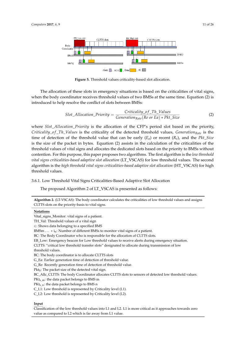
RCD-based BMSs contain high threshold values of vital signs, while CR-based BMSs containlow threshold values of vital signs. In the detection of a low threshold value of a vital sign, the BMStransmits an alert signal to the EB_Low slot as shown in Figure 5. The body coordinator replies back bysending an acknowledgment (ACK) to that BMS, and the BMS sends the reading of the low thresholdto CLTTS slots. The same process of slot allocation is followed for high threshold values using EB_Highfor an alert signal, and CHTTS slots are used for data transmission as shown in Figure 5.
Computers 2017, 6, 9 11 of 26
Computers 2017, 6, 9 10 of 26
ReCAL-CSMA/CA-based BMSs contend to access the channel of the CAP period in ranges between 4 and 7 times, while the CSMA/CA-based BMSs contend for accessing the channel in ranges between 0 and 7 times. Similarly, Round 4- and Round 5-based BMSs contend to access the channel in ranges between 8 and 15 times and between 16 and 31 times, respectively. The CSMA/CA-based BMSs contend to access the channels in the fourth and fifth rounds in ranges between 0 and 15 and between 0 and 31 times, respectively.
Clearly, the CSMA/CA scheme repeats the values of the contention in each round and drops the delay-sensitive patient data by exceeding values of the contention. However, the proposed ReCAL-CSMA/CA does not drop the patient’s data by allocating OD slot in the proposed Superframe structure of the TraySL-MAC, as shown in Step 6 of the algorithm.
3.5.2. Complexity Analysis
The body coordinator provides enough slots in the proposed Superframe structure of the TraySL-MAC. Additionally, it allocates a sufficient time period for BI and Superframe duration (SD). Let N_BMS_i be the number of BMSs to actively scanning channels in the CAP period, using maximum contention value N_aMaxb. Using these notations, the complexity of the ReCAL-CSMA/CA algorithm can be expressed as O(N_BMS_i, N_aMaxb). The values of the N_aMaxb can be determined using Equation (1).
3.6. Slot Allocation Based on the Criticalities of Threshold Values
This paper proposes VSCAS mechanisms allocating slots based on the alert signals to BMSs. For this purpose, we categorize the threshold values of the heartbeat rate (HR) [31,32], respiratory rate (RR) [33,34], blood pressure (BP) [35,36], and temperature (temp) [37,38] into different classes of high and low threshold values, as shown in Table 1. The criticality of Low1 threshold values is more in dangerous than Low2 because Low1 is approaching towards zero value. Similarly, the High1 threshold value is in the extreme boundaries as compared to High2.
Table 1. Threshold ranges of vital signs.
Vital Sign Normal Values Low Values High Values
Low1 (L1) Low2 (L2) High1 (H1) High2 (H2)HR 51–119 beats/min 0–25 beats/min 26–50 beats/min 141–180 beats/min 120–140 beats/min RR 12–19 breaths/min 0–6 breaths/min 7–11 breaths/min 41–60 breaths/min 20–40 breaths/min
BP (Systolic/ Diastolic) mm Hg
(90–120)/(60–80) (70–90)/(40–60) (140–190)/(90–100)
Temperature 37°C N/A 40°C & above 38°C to 39.9°C
RCD-based BMSs contain high threshold values of vital signs, while CR-based BMSs contain low threshold values of vital signs. In the detection of a low threshold value of a vital sign, the BMS transmits an alert signal to the EB_Low slot as shown in Figure 5. The body coordinator replies back by sending an acknowledgment (ACK) to that BMS, and the BMS sends the reading of the low threshold to CLTTS slots. The same process of slot allocation is followed for high threshold values using EB_High for an alert signal, and CHTTS slots are used for data transmission as shown in Figure 5.
Figure 5. Threshold values criticality-based slot allocation. Figure 5. Threshold values criticality-based slot allocation.
The allocation of these slots in emergency situations is based on the criticalities of vital signs,when the body coordinator receives threshold values of two BMSs at the same time. Equation (2) isintroduced to help resolve the conflict of slots between BMSs:
Slot_Allocation_Priority =Criticality_o f _Th_Values
GenerationRate(Re or Ea) ∗ Pkt_Size(2)
where Slot_Allocation_Priority is the allocation of the CFP’s period slot based on the priority,Criticality_o f _Th_Values is the criticality of the detected threshold values, GenerationRate is thetime of detection of the threshold value that can be early (Ea) or recent (Re), and the Pkt_Sizeis the size of the packet in bytes. Equation (2) assists in the calculation of the criticalities of thethreshold values of vital signs and allocates the dedicated slots based on the priority to BMSs withoutcontention. For this purpose, this paper proposes two algorithms. The first algorithm is the low thresholdvital signs criticalities-based adaptive slot allocation (LT_VSCAS) for low threshold values. The secondalgorithm is the high threshold vital signs criticalities-based adaptive slot allocation (HT_VSCAS) for highthreshold values.
3.6.1. Low Threshold Vital Signs Criticalities-Based Adaptive Slot Allocation
The proposed Algorithm 2 of LT_VSCAS is presented as follows:
Algorithm 2. (LT-VSCAS): The body coordinator calculates the criticalities of low threshold values and assignsCLTTS slots on the priority-basis to vital signs.
NotationsVital_signs_Monitor: vital signs of a patient.TH_Val: Threshold values of a vital sign∈: Shows data belonging to a specified BMSBMSm . . . + in: Number of different BMSs to monitor vital signs of a patient.BC: The Body Coordinator who is responsible for the allocation of CLTTS slots.EB_Low: Emergency beacon for Low threshold values to receive alerts during emergency situation.CLTTS: “critical low threshold transfer slots” designated to allocate during transmission of lowthreshold values.BC: The body coordinator is to allocate CLTTS slotsG_Ea: Earlier generation time of detection of threshold value.G_Re: Recently generation time of detection of threshold value.PktS: The packet size of the detected vital sign.BC_Allc_CLTTS: The body Coordinator allocates CLTTS slots to sensors of detected low threshold values.PKts_m: the data packet belongs to BMS mPKts_n: the data packet belongs to BMS nC_L1: Low threshold is represented by Criticality level (L1).C_L2: Low threshold is represented by Criticality level (L2).
InputClassification of the low threshold values into L1 and L2. L1 is more critical as it approaches towards zerovalue as compared to L2 which is far away from L1 value.

Computers 2017, 6, 9 12 of 26
ProcessSTART1. VitalsignsMonitor ← ∑n
m=1 BMSs2. for (each BMS transmit Th_Val belongs to Low) do3. if (BE_Low_to_BC← Transmits_alert_of_detected_ ∑n
m=1 BMSs) then4. if (BC ← received_Low_Threshold_value_ f rom_single_sensor) then
if(
BMS{
TH_Valnm}
__detected = = Low_Th_Val && (Gnm_Re OR Gn
m_Ea) && PktSm or n 6= 0)
thenn∑
m=1BMS← BC_allocates_Slot_CLTTS(Ti)
else Go To Monitoring statusend if
5. else if (BC_received_alerts_in_EB_Low == Low_Th_Vals && ∈{
TH_Valnm}
BMSs) thenif (BMSm_detected_Th_val == C _L1 && Gm−Ea && Pkts−m 6= 0) ==(BMSn_detected_Th_val == C _L1 && Gn−Ea && Pkts−n 6= 0) thenBMSm ← BC_Allc_CLTTS (Wk) && BMSn ← BC_Allc_CLTTS (Wk+1)
end if6. else if (BMSm_detected_Th_val == C _L1 && Gm−Ea && Pkts−m 6= 0) >
BMSn_detected_Th_val == C_L1 && Gn−Re && Pkts−n 6= 0) thenBMSm ← BC_Allc_CLTTS (Wk) && BMSn ← BC_Allc_CLTTS (Wk+1)
end if7. else if (BMSm_detected_Th_val == C _L1 && Gm−Re && Pkts−m 6= 0) <
BMSn_detected_Th_val == C _L1 && Gn−Ea && Pkts−n 6= 0) thenBMSn ← BC_Allc_CLTTS (Wk) && BMSm ← BC_Allc_CLTTS (Wk+1)
end if8. else if (BMSm_detected_Th_val == C _L1 && Gm−Re && Pkts−m 6= 0) ==
(BMSn_detected_Th_val == C _L1 && Gn−Re && Pkts−n 6= 0) thenBMSm ← BC_Allc_CLTTS (Wk ) && BMSn ← BC_Allc_CLTTS (Wk+1)
end if9. else if (BMSm_detected_Th_val == C _L1 && Gm−Ea && Pkts−m 6= 0) ==
(BMSn_detected_Th_val == C _L2 && Gn−Ea && Pkts−n 6= 0) thenBMSm←BC_Allc_CLTTS (Wk) && BMSn←BC_Allc_CLTTS (Wk+1)
end if10. else if (BMSm_detected_Th_val == C _L1 && Gm−Ea && Pkts−m 6= 0) >
(BMSn_detected_Th_val == C _L2 && Gn−Re && Pkts−n 6= 0) thenBMSm←BC_Allc_CLTTS (Wk) && BMSn ← BC_Allc_CLTTS (Wk+1)
end if11. else if (BMSm_detected_Th_val == C _L1 && Gm−Re && Pkts−m 6= 0) <
(BMSn_detected_Th_val == C _L2 && Gn−Ea && Pkts−n 6= 0) thenBMSn←BC_Allc_CLTTS (Wk) && BMSm ← BC_Allc_CLTTS (Wk+1)
end if12. else if (BMSm_detected_Th_val == C _L1 && Gm−Re && Pkts−m 6= 0) ==
(BMSn_detected_Th_val == C _L2 && Gn−Re && Pkts−n 6= 0) thenBMSm←BC_Allc_CLTTS (Wk) && BMSn ← BC_Allc_CLTTS (Wk+1)
end if13. else if (BMSm_detected_Th_val == C _L2 && Gm−Ea && Pkts−m 6= 0) ==
(BMSn_detected_Th_val == C _L1 && Gn−Ea && Pkts−n 6= 0) thenBMSn ← BC_Allc_CLTTS (Wk) && BMSm ← BC_Allc_CLTTS (Wk+1)
end if14. else i f (BMSm_detected_Th_val == C _L2 && Gm−Ea && Pkts−m 6= 0) >
(BMSn_detected_Th_val == C _L1 && Gn−Re && Pkts−n 6= 0) thenBMSm ← BC_Allc_CLTTS (Wk) && BMSn ← BC_Allc_CLTTS (Wk+1)
end if15. else i f (BMSm_detected_Th_val == C _L2 && Gm−Re && Pkts−m 6= 0) <
(BMSn_detected_Th_val == C _L1 && Gn−Ea && Pkts−n 6= 0) thenBMSn ← BC_Allc_CLTTS (Wk) && BMSm ← BC_Allc_CLTTS (Wk+1)
end if
Computers 2017, 6, 9 13 of 26
16. else if (BMSm_detected_Th_val == C _L2 && Gm−Re && Pkts−m 6= 0) ==
(BMSn_detected_Th_val == C _L1 && Gn−Re && Pkts−n 6= 0) thenBMSn ← BC_Allc_CLTTS (Wk) && BMSm ← BC_Allc_CLTTS (Wk+1)
end if17. else if (BMSm_detected_Th_val == C _L2 && Gm−Ea && Pkts−m 6= 0) ==
(BMSn_detected_Th_val == C _L2 && Gn−Ea && Pkts−n 6= 0) thenBMSm ← BC_Allc_CLTTS (Wk) && BMSn ← BC_Allc_CLTTS (Wk+1)
end if18. else if (BMSm_detected_Th_val == C _L2 && Gm−Ea && Pkts−m 6= 0) >
(BMSn_detected_Th_val == C _L2 && Gn−Re && Pkts−n 6= 0) thenBMSm ← BC_Allc_CLTTS (Wk) && BMSn ← BC_Allc_CLTTS (Wk+1)
end if19. else if (BMSm_detected_Th_val == C _L2 && Gm−Re && Pkts−m 6= 0) <
(BMSn_detected_Th_val == C _L2 && Gn−Ea && Pkts−n 6= 0) thenBMSn ← BC_Allc_CLTTS (Wk) && BMSm ← BC_Allc_CLTTS (Wk+1)
end if20. else if (BMSm_detected_Th_val == C _L2 && Gm−Re && Pkts−m 6= 0) ==
(BMSn_detected_Th_val == C _L2 && Gn−Re && Pkts−n 6= 0) thenBMSm ← BC_Allc_CLTTS (Wk) && BMSn ← BC_Allc_CLTTS (Wk+1)
end ifelse Go to sleep or monitor the vital sign
end ifend if
end ifend forENDOutput: Allocation of CLTTS slots to low threshold values based on the criticalities of vital signs
3.6.2. Explanation of Steps of LT_VSCAS Algorithm
We have classified low threshold values into Criticality Low1 (C_L1) and Criticality Low2 (C_L2).Low1 data is more critical than those of Low2, because Low1 approaches a zero value. The Ea andRe are associated with the low threshold values and assists in the decision of slot allocation to BMSs.The LT_VSCAS Algorithm 2 presents two scenarios and considers n of the BMS vital signs of a patient,as shown in Steps 1–3. The first scenario consists of a single BMS, as shown in Step 4, while thesecond scenario presents two BMSs, as shown in Step 5. If a single BMS detects and transmits lowthreshold values using EB_Low slot of the Superframe structure. In this situation, the body coordinatorassigns CLTTS slots without checking the other two parameters. In the second scenario, the bodycoordinator takes decision of slot allocation based on the priority between two low threshold values ofBMSs, which assists in removing the conflict of slot allocation between them. In Step 5, both BMS_mand BMS_n detect Low1 with Ea. The body coordinator allocates slots in ascending first to BMS_nand then to BMS_n. In Step 6, BMS_m generates data with Ea and BMS_n generates data with Re,but both BMSs detect Low1. In this situation, the body coordinator assigns the first slot to BMS_mand the second slot to BMS_n. In Step 7, BMS_m generates data with Re and BMS_n generates datawith Ea, but both BMSs detect Low1. In this situation, the body coordinator assigns the first slot toBMS_n and the second slot to BMS_m. In Step 8, both BMS_m and BMS_n detect Low1 with the sameRe. The decision of slot allocation is followed as used in Step 5. BMS_m detects Low1 and BMS_ndetects Low2, but their generation rates are Ea as shown in Step 9. The body coordinator allocates thefirst slot to BMS_m and the second slot to BMS_n. Step 10 contains the same low thresholds as shownin Step 9, but BMS_m generates data with Ea and BMS_n generates data with Re. The same decision ofslot allocation is used as shown in Step 9. Both BMSs detect the same low threshold values as shownin Step 11 and are similar to those in Step 10, but BMS_m generates with Re and BMS_n generates withEa. The decision of slot allocation is first to BMS_n and secondly to BMS_m. Step 12 shows that both
Computers 2017, 6, 9 14 of 26
BMSs detect the same low thresholds as shown in Step 11. Additionally, their generation rates of dataare same Re. The same decision of slot allocation is used as described in Step 10.
The BMS_m detects Low2 and BMS_n detects Low1, but their generation rates are the same Ea,as shown in Step 13. The decision of slot allocation is employed as described in Step 11. Step 14 showsthe same detected threshold values as described in Step 13, but BMS_m generates data with Ea andBMS_n generates data with Re. The same decision of slot allocation is made as shown in Step 12.The generation rates of data are the inverse of both BMSs as shown in Step 15, as compared to Step 14,but their detected threshold values are the same. The same slot allocation decision is used as shownin Step 13. In Step 16, both BMSs detect the same threshold values as shown in Step 15, but theirgeneration rates of data are same that is Re. Similar decisions of slot allocation are made as shown inStep 15. In Steps 17–20, both BMSs detect Low2 with different generation rates. For Step 17, both BMSsgenerate data with Ea and the decision of slot allocation is the same as that shown in Step 15. In Step 18,BMS_m generates data with Ea and BMS_n generates data with Re. The same decision of slot allocationis made, as shown in Step 17. The generation rates of data in Step 19 are the inverse of Step 18, but thedecision of slot allocation is the same as that made in Step 16. In Step 20, both BMSs generate data withRe, but the slot allocation decision is followed as shown in Step 18. BMSs go into a mode of monitoringvital signs or sleep mode if these are not the conditions related to the vital signs as shown in algorithm.The complexity analysis of Algorithm 2 is presented in Section 3.6.5.
3.6.3. High Threshold Vital Signs Criticalities-Based Adaptive Slot Allocation
The proposed Algorithm 3 of HT_VSCAS shows the allocation of CHTTS slots between BMSswhen they transmit alert signals at the same time to the slot of EB_High of the body coordinatoras follows:
Algorithm 3. (HT-VSCAS): The body coordinator calculates the criticalities of high threshold values andassigns CHTTS slots on the priority-basis to vital signs.
NotationsVital_signs_Monitor: vital signs of a patient.TH_Val: Threshold values of a vital sign∈: Shows data belonging to a specified BMSBMSm . . . + in: Number of different BMSs to monitor vital signs of a patient.BC: Body Coordinator who is responsible for the allocation of CHTTS slots.EB_High: Emergency beacon for High threshold values to receive alerts during emergency situation.CHTTS: “critical high threshold transfer slots” designated to allocate during transmission of highthreshold values.G_Ea: Earlier generation time of detection of threshold value.G_Re: Recently generation time of detection of threshold value.PktS: The packet size of the detected vital sign.BC_Allc_CHTTS: The body Coordinator allocates CHTTS slots to sensors of detected high threshold values.PKts_m: the data packet belongs to BMS mPKts_n: the data packet belongs to BMS nC_H1: High threshold represents by Criticality level (H1) as it is more critical as compared to H2.C_H2: High threshold represents by Criticality level (H2).
InputClassification of the High threshold values in H1 and H2. H1 contains more critical data as compared to H2because the ranges of H1 is greater than H2.
Computers 2017, 6, 9 15 of 26
ProcessSTART1. VitalsignsMonitor ← ∑n
m=1 BMSs2. for (each BMS transmit Th_Val belongs to high) do3. if (BE_high_to_BC← Transmits_alert_of_detected_ ∑n
m=1 BMSs) then4. if (BC ← received_high_Threshold_value_ f rom_single_sensor) then5. if
(BMS
{TH_Val
nm}
__detected = = High && ( Gnm_Re OR Gn
m_Ea) && PktSm,n 6= 0)
thenn∑
m=1BMSs ← BC_allocates_Slot_CHTTS(Ti)
else Go To Monitoring statusend if
6. else if (BC_received_alert_in_EB_High == High_Th_Val && ∈{
TH_Valnm}
BMSs ) then7. if (BMSm_detected_Th_val == C _H1 && Gm−Ea && Pkts−m 6= 0) ==
BMSn_detected_Th_val == C _H1 && Gn−Ea && Pkts−n 6= 0) thenBMSm ← BC_Allc_CLTTS (Wk) && BMSn ← BC_Allc_CLTTS (Wk+1)
end if8. else if (BMSm_detected_Th_val == C_H1 &&Gm−Ea && Pkts−m 6= 0) >
(BMSn_detected_Th_val == C _H1 && Gn−Re && Pkts−n 6= 0) thenBMSm ← BC_Allc_CHTTS (Wk) && BMSn ← BC_Allc_CHTTS (Wk+1)
end if9. else i f (BMSm_detected_Th_val == C _H1 && Gm−Re && Pkts−m 6= 0) <
BMSn_detected_Th_val == C _H1 && Gn−Ea && Pkts−n 6= 0) thenBMSn ← BC_Allc_CHTTS (Wk) && BMSm ← BC_Allc_CHTTS (Wk+1)
end if10. else if (BMSm_detected_Th_val == C_H1 && Gm−Ea && Pkts−m 6= 0) = =
(BMSn_detected_Th_val == C_H1&& Gn−Re && Pkts−n 6= 0) thenBMSm ← BC_Allc_CLTTS (Wk) && BMSn ← BC_Allc_CLTTS (Wk+1)
end if11. else if (BMSm_detected_Th_val == C_H1 && Gm−Ea && Pkts−m 6= 0) = =
(BMSn_detected_Th_val == C_H2&& Gn−Ea && Pkts−n 6= 0) thenBMSm ← BC_Allc_CLTTS (Wk) && BMSn ← BC_Allc_CLTTS (Wk+1)
end if12. else if (BMSm_detected_Th_val == C_H1 && Gm−Ea && Pkts−m 6= 0) >
(BMSn_detected_Th_val == C _H2&& Gn−Re && Pkts−n 6= 0) thenBMSm ← BC_Allc_CLTTS (Wk) && BMSn ← BC_Allc_CLTTS (Wk+1)
end if13. else if (BMSm_detected_Th_val == C_H1 && Gm−Re && Pkts−m 6= 0) <
(BMSn_detected_Th_val == C_H2&& Gn−Ea && Pkts−n 6= 0) thenBMSm ← BC_Allc_CLTTS (Wk) && BMSm ← BC_Allc_CLTTS ( Wk+1)
end if14. else if (BMSm_detected_Th_val == C_H1 && Gm−Re && Pkts−m 6= 0) = =
(BMSn_detected_Th_val == C_H2&& Gn−Re && Pkts−n 6= 0) thenBMSn ← BC_Allc_CLTTS (Wk) && BMSm ← BC_Allc_CLTTS (Wk+1)
end if15. else if (BMSm_detected_Th_val == C_H2 && Gm−Ea && Pkts−m 6= 0) = =
(BMSn_detected_Th_val == C_H1 && Gn−Ea && Pkts−n 6= 0) thenBMSn ← BC_Allc_CLTTS (Wk) && BMSm ← BC_Allc_CLTTS (Wk+1)
end if16. else if (BMSm_detected_Th_val == C_H2 && Gm−Ea && Pkts−m 6= 0) >
(BMSn_detected_Th_val == C_H1 && Gn−Re && Pkts−n 6= 0) thenBMSm ← BC_Allc_CLTTS (Wk) && BMSn ← BC_Allc_CLTTS (Wk+1)
end if
Computers 2017, 6, 9 16 of 26
17. else if (BMSm_detected_Th_val == C_H2 && Gm−Re && Pkts−m 6= 0) <(BMSn_detected_Th_val == C_H1&& Gn−Ea && Pkts−n 6= 0) thenBMSn ← BC_Allc_CLTTS (Wk) && BMSm ← BC_Allc_CLTTS (Wk+1)
end if18. else if (BMSm_detected_Th_val == C_H2 && Gm−Re && Pkts−m 6= 0) = =
(BMSn_detected_Th_val == C_H1 && Gn−Re && Pkts−n 6= 0) thenBMSn ← BC_Allc_CLTTS (Wk) && BMSm ← BC_Allc_CLTTS (Wk+1)
end if19. else if (BMSm_detected_Th_val == C_H2 && Gm−Ea && Pkts−m 6= 0) = =
(BMSn_detected_Th_val == C_H2 && Gn−Ea && Pkts−n 6= 0) thenBMSm ← BC_Allc_CLTTS (Wk) && BMSn ← BC_Allc_CLTTS (Wk+1)
end if20. else if (BMSm_detected_Th_val == C_H2 && Gm−Ea && Pkts−m 6= 0) >
(BMSn_detected_Th_val == C_H2 && Gn−Re && Pkts−n 6= 0) thenBMSm ← BC_Allc_CLTTS (Wk) && BMSn ← BC_Allc_CLTTS (Wk+1)
end if21. else if (BMSm_detected_Th_val == C_H2 && Gm−Re && Pkts−m 6= 0) <
(BMSn_detected_Th_val == C_H2 && Gn−Ea && Pkts−n 6= 0) thenBMSn ← BC_Allc_CLTTS (Wk) && BMSm ← BC_Allc_CLTTS (Wk+1)
end if22. else if (BMSm_detected_Th_val == C_H2 && Gm−Re && Pkts−m 6= 0) = =
(BMSn_detected_Th_val == C_H2 && Gn−Re && Pkts−n 6= 0) thenBMSm ← BC_Allc_CLTTS (Wk) && BMSn ← BC_Allc_CLTTS (Wk+1)
end ifelse Go to sleep or monitor the vital sign
end ifend if
end ifend forENDOutput: Allocation of CHTTS slots to high threshold values based on the criticalities of vital signs
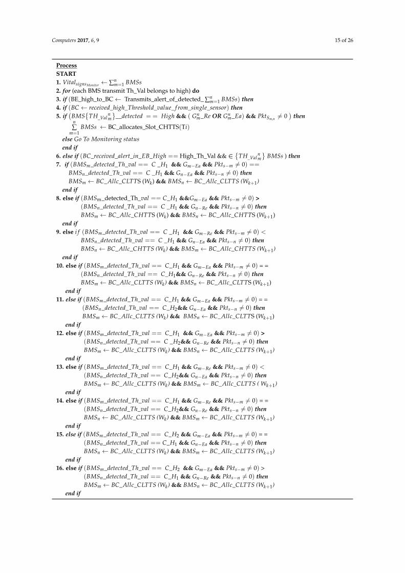
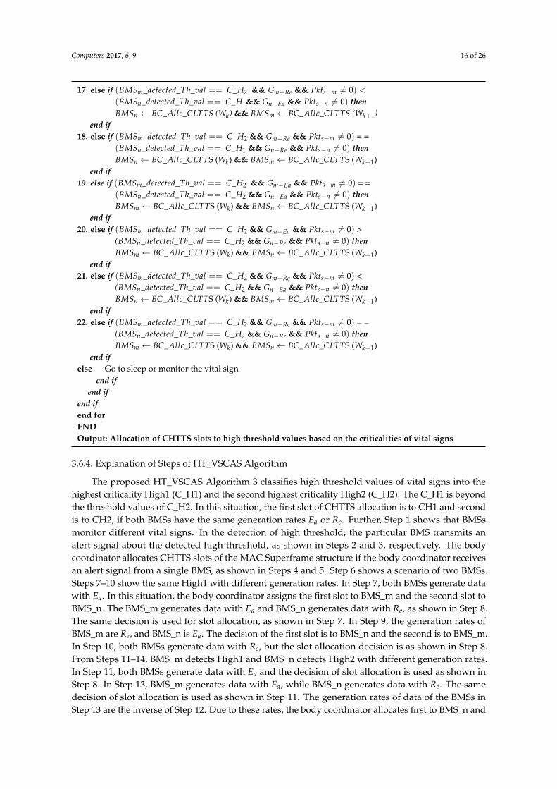
3.6.4. Explanation of Steps of HT_VSCAS Algorithm
The proposed HT_VSCAS Algorithm 3 classifies high threshold values of vital signs into thehighest criticality High1 (C_H1) and the second highest criticality High2 (C_H2). The C_H1 is beyondthe threshold values of C_H2. In this situation, the first slot of CHTTS allocation is to CH1 and secondis to CH2, if both BMSs have the same generation rates Ea or Re. Further, Step 1 shows that BMSsmonitor different vital signs. In the detection of high threshold, the particular BMS transmits analert signal about the detected high threshold, as shown in Steps 2 and 3, respectively. The bodycoordinator allocates CHTTS slots of the MAC Superframe structure if the body coordinator receivesan alert signal from a single BMS, as shown in Steps 4 and 5. Step 6 shows a scenario of two BMSs.Steps 7–10 show the same High1 with different generation rates. In Step 7, both BMSs generate datawith Ea. In this situation, the body coordinator assigns the first slot to BMS_m and the second slot toBMS_n. The BMS_m generates data with Ea and BMS_n generates data with Re, as shown in Step 8.The same decision is used for slot allocation, as shown in Step 7. In Step 9, the generation rates ofBMS_m are Re, and BMS_n is Ea. The decision of the first slot is to BMS_n and the second is to BMS_m.In Step 10, both BMSs generate data with Re, but the slot allocation decision is as shown in Step 8.From Steps 11–14, BMS_m detects High1 and BMS_n detects High2 with different generation rates.In Step 11, both BMSs generate data with Ea and the decision of slot allocation is used as shown inStep 8. In Step 13, BMS_m generates data with Ea, while BMS_n generates data with Re. The samedecision of slot allocation is used as shown in Step 11. The generation rates of data of the BMSs inStep 13 are the inverse of Step 12. Due to these rates, the body coordinator allocates first to BMS_n and

Computers 2017, 6, 9 17 of 26
second to BMS_m. In Step 14, both BMSs generate data with Re. In this situation, the same decision forslot allocation is considered as shown in Step 12.
From Steps 15–18, BMS_m detects High2, and BMS_n detects High1 with different generationrates. In Step 15, both BMSs generate data with Ea and the decision of slot allocation is used as shownin Step 13. In Step 16, BMS_m generates data with Ea, while BMS_n generates data with Re. The samedecision of slot allocation is used as shown in Step 14. The generation rates of data of the BMSs inStep 17 are the inverse of Step 16. Due to these rates, the body coordinator allocates first to BMS_n andsecond to BMS_m. In Step 18, both BMSs generate data with Re. In this situation, the same decision forslot allocation is used as shown in Step 13. From Steps 19–22, both BMSs detect the High2 thresholdwith different generation rates. In Step 18, both BMSs generate data with Re, and the decision of slotallocation is used as shown Step 17. In Step 19, both BMSs generate data with Ea, and the decisionof slot allocation is used as shown in Step 16. The generation rate of data of BMS_m is Ea, and thatof BMS_n is Re as shown in Step 20. In this situation, the body coordinator allocates first to BMS_nand second to BMS_m. In Step 21, the generation rates of data of BMSs are the inverse of Step 20.The decision of slot allocation is first to BMS_n and second to BMS_m. In Step 22, both BMSs generatedata with Re and the decision of slot allocation is used as shown in Step 20. If these are not theconditions related to the vital signs, BMSs go into a mode of monitoring of vital signs or sleep mode.
3.6.5. Complexity Analysis of LT_VSCAS and HT_VSCAS Algorithms
The working procedures of algorithms LT_CSCAS and HT_VSCAS are the same, exceptwhen allocating CLTTS and CHTTS slots to low and high threshold values, respectively. Due tothese, the complexity analysis is the same. Let N_BMS_i be the number of BMSs to monitorvarious vital signs of a patient. In the detection of threshold values, the particular BMS requestsdedicated (CLTTS or CHTTS) slots of the CFP period using an alert signal (EB_Low or EB_High).Using these notations, the complexity of the LT_VSCAS algorithm can be expressed as O(N_BMS_ilog(N_BMS_i(CLTTS)). Similarly, the complexity of the HT_VSCAS algorithm can be expressed asO(N_Node_i log(N_BMS_i(CHTTS)). The process of these slot allocation, whether it is CLTTS or CHTTS toBMSs, can be determined using Equation (2).
4. Performance Evaluation
The simulation is performed in NS-2, and the results are categorized into two phases. Phase 1compares the performance of each rounds of the contention of the proposed ReCAL-CSMA/CAscheme with the standard CSMA/CA scheme. The performance is compared in terms of the packetdelivery delay, throughput, and energy consumption of the BMSs. In the second phase of simulation,the performance of the proposed TraySL-MAC protocol is compared with state-of-the-art MACprotocols—IEEE 802.15.4 MAC [7], LTDA-MAC [12], and PLA-MAC [10]. Table 2 shows the parameterlist for both phases of simulation, which are used in NS-2. Moreover, 14 BMSs are deployed andconnected with a body coordinator in the star topology to monitor various vital signs of a patient’sbody. All these BMSs are static and the simulation coverage area is 3 × 2 m. The simulation runsfor 2000 s.

Computers 2017, 6, 9 18 of 26
Table 2. Simulation parameters.
Parameter Value Parameter Value
Operating Carrier Frequency 2.4 GHz aBaseSlot_Duration 60 symbolsChannel Rate 250 kbps Sending Data Rates 20 kbps
Number of channels in the proposedTraySL-MAC and PLA-MAC
Superframe structure128 MAC Payload size 1920 bytes
Number of channels in IEEE 802.15.4and LTDA-MAC 16 and 32 Buffer size of the Body Coordinator 2000 bytes
BO set for all MAC protocols 10 Buffer size of a BMS 1920 bytesSO set for all MAC protocols 9 Max PHY Packet Size 127 bytes
A Slot Duration 1.536 s TurnaroundTime 12 SymbolsCCA Time 8 symbols UnitBackoffPeriod 20 symbols
Max Frame Retries 4 macAckWaitDuration 54Carrier sense sensitivity −97 mW macMinBE—for Standard IEEE 802.15.4 3
Receiver sense sensitivity −97 mW BI in seconds 393.216 sTime of Superframe Duration (SD) 196.608 s BI in Symbols 7864320 symbols
Low data generation rate 0.5 ms Data generation rate 1.5 msTraffic Type CBR Power Consumed in Sleep state 0.005 mW
Power Consumed in Transmissionstate 27–220 mW Power Consumed in Receive state 1.8 mW
Duration of Turn-On radio toTransmit/Receive data 0.8 ms
Power required for radio to switch fromtransmitting state to receive state &
vice versa0.4 ms
4.1. Evaluation of ReCAL-CSMA/CA
The average packet delay of the proposed ReCAL-CSMA/CA scheme is compared with theCSMA/CA scheme as shown in Figure 6. The data generation rate is 1.5 ms considered for bothschemes. In the first round of contention, the average packet delay is reduced by 90% (green lines)in the ReCAL-CSMA/CA as shown in Figure 6. This performance is achieved due to the sufficientchannels, the sufficient time periods of BI, the Superframe duration (SD), and the slot duration,as compared to a CSMA/CA in the first round. For the second, third, fourth, and fifth rounds of thecontention, Equation (1) assists to reduce the repetition in rounds of the contention. Thus, the averagepacket delay is reduced in the second round by 87%, 80% in the third round, 77% in the fourth, and 73%in the fifth round. The CSMA/CA-based BMSs exceed threshold values (aMaxb) of the contentionquickly as the traffic loads increase. This degraded performance of the CSMA/CA increases thewaiting time of BMSs for new BI and increases the delay of the packets. Other issues of delay includedropping the patient’s data. However, the dropping of data packets in the proposed scheme is handledby using the OD slot of the TraySL-MAC Superframe structure.
The average packet delivery ratio (PDR) of the ReCAL-CSMA/CA is compared with a CSMA/CAas shown in Figure 7. The TraySL-MAC Superframe structure provides sufficient channels and thebandwidth of each channel for data transmission is 9.375 MHz. The guardband between channelsis 0.1 MHz by protecting channels from overlapping. Equation (1) is used in the implementationof a ReCAL-CSMA/CA for reducing contention. The sufficient channels, the guardband betweenchannels, and the reduced rounds of the contention are the advantages of transmitting a large amountof a patient’s data without interrupting others BMSs. For the first round of contention, the averagePDR of the CDASA-CSMA/CA is achieved by 27% as compared to a CSMA/CA because the MACSuperframe structure of IEEE 802.15.4 is limited to 16 channels, and the CSMA/CA repeats the roundsof the contention. For the second and third rounds of contention, the PDR of the CDASA-CSMA/CAis achieved by 11% and 24%, respectively, as shown in Figure 7. For the fourth and fifth rounds ofthe contention, the CDASA-CSMA/CA has reduced the steps for accessing the channels, and BMSstransmit data directly by performing a CCA activity for collision-free channel access. Thus, the achievedPDR in the fourth and fifth rounds are 26% and 17%, respectively, as compared to a CSMA/CA. As moreBMSs exceed the threshold value (aMaxb) in the CSMA/CA, the PDR goes down due to the limited

Computers 2017, 6, 9 19 of 26
number of channels in the IEEE 802.15.4 MAC Superframe structure, and BMSs wait to transmit thepatient’s data in the next announcement of BI.Computers 2017, 6, 9 19 of 26
Figure 6. Average packet delivery delay ratio of the ReCAL-CSMA/CA vs. CSMA/CA.
Figure 7. Average packet delivery ratio of the ReCAL-CSMA/CA vs. CSMA/CA.
The low energy consumption model [30] is used in the implementation for the ReCAL-CSMA/CA. The reduced round-based energy consumption of the ReCAL-CSMA/CA scheme is minimal because dedicated and sufficient bandwidth of the slots is allocated to various BMSs. In addition, the proposed TraySL-MAC provides a sufficient time period of BI, and BMSs transmit data in the same BI. However, these features are the limitations of the MAC Superframe structure of IEEE 802.15.4 and CSMA/CA. In the first round of contention, the ReCAL-CSMA/CA needs 27 mW energy for data transmission, which is the minimum, as compared to a CSMA/CA. The achieved minimum energy consumption is 20% in the first round of the contention of the ReCAL-CSMA/CA as shown in Figure 8. Moreover, the repetition of rounds in the CSMA/CA increases the contention for accessing the channels in the CAP period. These increasing numbers in rounds of contention consume more energy due to the limited channels. In this way, the performance of the MAC Superframe structure of IEEE 802.15.4 is degraded, causing a higher collision, and BMSs retransmit the collided packets with a higher delay. Hence, the average energy consumption of BMSs in the Superframe structure is reduced and saves energy up to 43%, 49%, 46%, and 58% in Round 2, Round 3, Round 4, and Round 5, respectively.
Figure 6. Average packet delivery delay ratio of the ReCAL-CSMA/CA vs. CSMA/CA.
Computers 2017, 6, 9 19 of 26
Figure 6. Average packet delivery delay ratio of the ReCAL-CSMA/CA vs. CSMA/CA.
Figure 7. Average packet delivery ratio of the ReCAL-CSMA/CA vs. CSMA/CA.
The low energy consumption model [30] is used in the implementation for the ReCAL-CSMA/CA. The reduced round-based energy consumption of the ReCAL-CSMA/CA scheme is minimal because dedicated and sufficient bandwidth of the slots is allocated to various BMSs. In addition, the proposed TraySL-MAC provides a sufficient time period of BI, and BMSs transmit data in the same BI. However, these features are the limitations of the MAC Superframe structure of IEEE 802.15.4 and CSMA/CA. In the first round of contention, the ReCAL-CSMA/CA needs 27 mW energy for data transmission, which is the minimum, as compared to a CSMA/CA. The achieved minimum energy consumption is 20% in the first round of the contention of the ReCAL-CSMA/CA as shown in Figure 8. Moreover, the repetition of rounds in the CSMA/CA increases the contention for accessing the channels in the CAP period. These increasing numbers in rounds of contention consume more energy due to the limited channels. In this way, the performance of the MAC Superframe structure of IEEE 802.15.4 is degraded, causing a higher collision, and BMSs retransmit the collided packets with a higher delay. Hence, the average energy consumption of BMSs in the Superframe structure is reduced and saves energy up to 43%, 49%, 46%, and 58% in Round 2, Round 3, Round 4, and Round 5, respectively.
Figure 7. Average packet delivery ratio of the ReCAL-CSMA/CA vs. CSMA/CA.
The low energy consumption model [30] is used in the implementation for the ReCAL-CSMA/CA.The reduced round-based energy consumption of the ReCAL-CSMA/CA scheme is minimal becausededicated and sufficient bandwidth of the slots is allocated to various BMSs. In addition, the proposedTraySL-MAC provides a sufficient time period of BI, and BMSs transmit data in the same BI. However,these features are the limitations of the MAC Superframe structure of IEEE 802.15.4 and CSMA/CA.In the first round of contention, the ReCAL-CSMA/CA needs 27 mW energy for data transmission,which is the minimum, as compared to a CSMA/CA. The achieved minimum energy consumption is20% in the first round of the contention of the ReCAL-CSMA/CA as shown in Figure 8. Moreover,the repetition of rounds in the CSMA/CA increases the contention for accessing the channels in theCAP period. These increasing numbers in rounds of contention consume more energy due to thelimited channels. In this way, the performance of the MAC Superframe structure of IEEE 802.15.4 isdegraded, causing a higher collision, and BMSs retransmit the collided packets with a higher delay.Hence, the average energy consumption of BMSs in the Superframe structure is reduced and savesenergy up to 43%, 49%, 46%, and 58% in Round 2, Round 3, Round 4, and Round 5, respectively.

Computers 2017, 6, 9 20 of 26Computers 2017, 6, 9 20 of 26
Figure 8. Average energy consumption of BMSs of the ReCAL-CSMA/CA vs. CSMA/CA.
4.2. Comparative Evaluation
The performance of the proposed TraySL-MAC protocol based on the ReCAL-CSMA/CA, LT-VSCAS, and HT-VSCAS schemes are compared with IEEE 802.15.4 [7], LTDA-MAC [12], and PLA-MAC [10] in terms of packet delivery delay, delivery delay for delay-driven packets, throughput, and energy consumption. The values of BO = 10 and SO = 9 are configured in NS-2 under the package ns-2.34 for all MAC protocols. IEEE 802.15.4 MAC provides BI = 49.152 s (983040 symbols), an SD of 24.576 s, and a slot duration of 1.536 s. The LTDA-MAC provides BI = 98.307 s (1966080 symbols), an SD of 49.152 s, and a slot duration of 1.536 s. The proposed TraySL-MAC and PLA-MAC provide 128 slots in the MAC Superframe structure. Both MAC Superframe structures announce a new BI after 393.216 s (7864320 symbols), an SD of 196.608 s, and a slot duration of 1.536 s. However, their provided functionalities and working procedures of the slot allocation to different types of a patient’s data are different.
4.2.1. Analysis of Packet Delivery Delay
Each BMS is given a specific amount of time to transmit a data packet to the body coordinator. As more BMSs transmit data packets, the collision increases in IEEE 802.15.4 MAC, as shown in Figure 9. The reason is that IEEE 802.15.4 provides only 16 slots, and 14 BMSs repeat the rounds of the contention in accessing the channel in the fixed seven slots of the CAP period. During the repetition in rounds of contention, the body coordinator announces the next BI after 49 s, which does not provide sufficient time for all BMSs to contend and access a channel. The body coordinator allocates seven guaranteed timeslots (GTSs) of the CFP period to those BMSs that obtained channel access in the CAP. With limited slots, increased contention, and the frequent announcement of a new BI, the patient’s data confronts the highest delay as the number of data packets increase for transmission, as depicted in Figure 9. Additionally, the same situation is noticed in LTD-MAC, where few data packets are transmitted in the same BI, and the maximum number of data packets are transmitted in the subsequent BI. As the number of BMSs for data packets transmission increases, the collision rate increases because of the 32 slots provided in LTD-MAC and the increased contention. In the PLA-MAC protocol, the delay increases gradually after data transmission of the fifth BMS, because all four types of data perform contention in the fixed slots of the CAP period. The allocation of CFP slots in the PLA-MAC takes a considerably higher amount of time because the body coordinator cannot allocate slots to all data packets in the same SD due to the contention and the fixed slots in the CAP period. The collision increases and BMSs retransmit the collided data packets by degrading the performance of the PLA-MAC protocol. The lowest average packet delivery delay is noticed in the TraySL-MAC protocol. The judgment is that the CAP period provides 24 slots and reduces the contention of BMSs, whereas the body coordinator allocates NDTS slots of the CFP period in the same BI without waiting for the next BI. Thus, the TraySL-MAC reduces the packet delay and
Figure 8. Average energy consumption of BMSs of the ReCAL-CSMA/CA vs. CSMA/CA.
4.2. Comparative Evaluation
The performance of the proposed TraySL-MAC protocol based on the ReCAL-CSMA/CA,LT-VSCAS, and HT-VSCAS schemes are compared with IEEE 802.15.4 [7], LTDA-MAC [12],and PLA-MAC [10] in terms of packet delivery delay, delivery delay for delay-driven packets,throughput, and energy consumption. The values of BO = 10 and SO = 9 are configured in NS-2under the package ns-2.34 for all MAC protocols. IEEE 802.15.4 MAC provides BI = 49.152 s(983040 symbols), an SD of 24.576 s, and a slot duration of 1.536 s. The LTDA-MAC provides BI = 98.307 s(1966080 symbols), an SD of 49.152 s, and a slot duration of 1.536 s. The proposed TraySL-MAC andPLA-MAC provide 128 slots in the MAC Superframe structure. Both MAC Superframe structuresannounce a new BI after 393.216 s (7864320 symbols), an SD of 196.608 s, and a slot duration of 1.536 s.However, their provided functionalities and working procedures of the slot allocation to differenttypes of a patient’s data are different.
4.2.1. Analysis of Packet Delivery Delay
Each BMS is given a specific amount of time to transmit a data packet to the body coordinator.As more BMSs transmit data packets, the collision increases in IEEE 802.15.4 MAC, as shown inFigure 9. The reason is that IEEE 802.15.4 provides only 16 slots, and 14 BMSs repeat the roundsof the contention in accessing the channel in the fixed seven slots of the CAP period. During therepetition in rounds of contention, the body coordinator announces the next BI after 49 s, which doesnot provide sufficient time for all BMSs to contend and access a channel. The body coordinator allocatesseven guaranteed timeslots (GTSs) of the CFP period to those BMSs that obtained channel accessin the CAP. With limited slots, increased contention, and the frequent announcement of a new BI,the patient’s data confronts the highest delay as the number of data packets increase for transmission,as depicted in Figure 9. Additionally, the same situation is noticed in LTD-MAC, where few datapackets are transmitted in the same BI, and the maximum number of data packets are transmitted inthe subsequent BI. As the number of BMSs for data packets transmission increases, the collision rateincreases because of the 32 slots provided in LTD-MAC and the increased contention. In the PLA-MACprotocol, the delay increases gradually after data transmission of the fifth BMS, because all four typesof data perform contention in the fixed slots of the CAP period. The allocation of CFP slots in thePLA-MAC takes a considerably higher amount of time because the body coordinator cannot allocateslots to all data packets in the same SD due to the contention and the fixed slots in the CAP period.The collision increases and BMSs retransmit the collided data packets by degrading the performanceof the PLA-MAC protocol. The lowest average packet delivery delay is noticed in the TraySL-MACprotocol. The judgment is that the CAP period provides 24 slots and reduces the contention of BMSs,
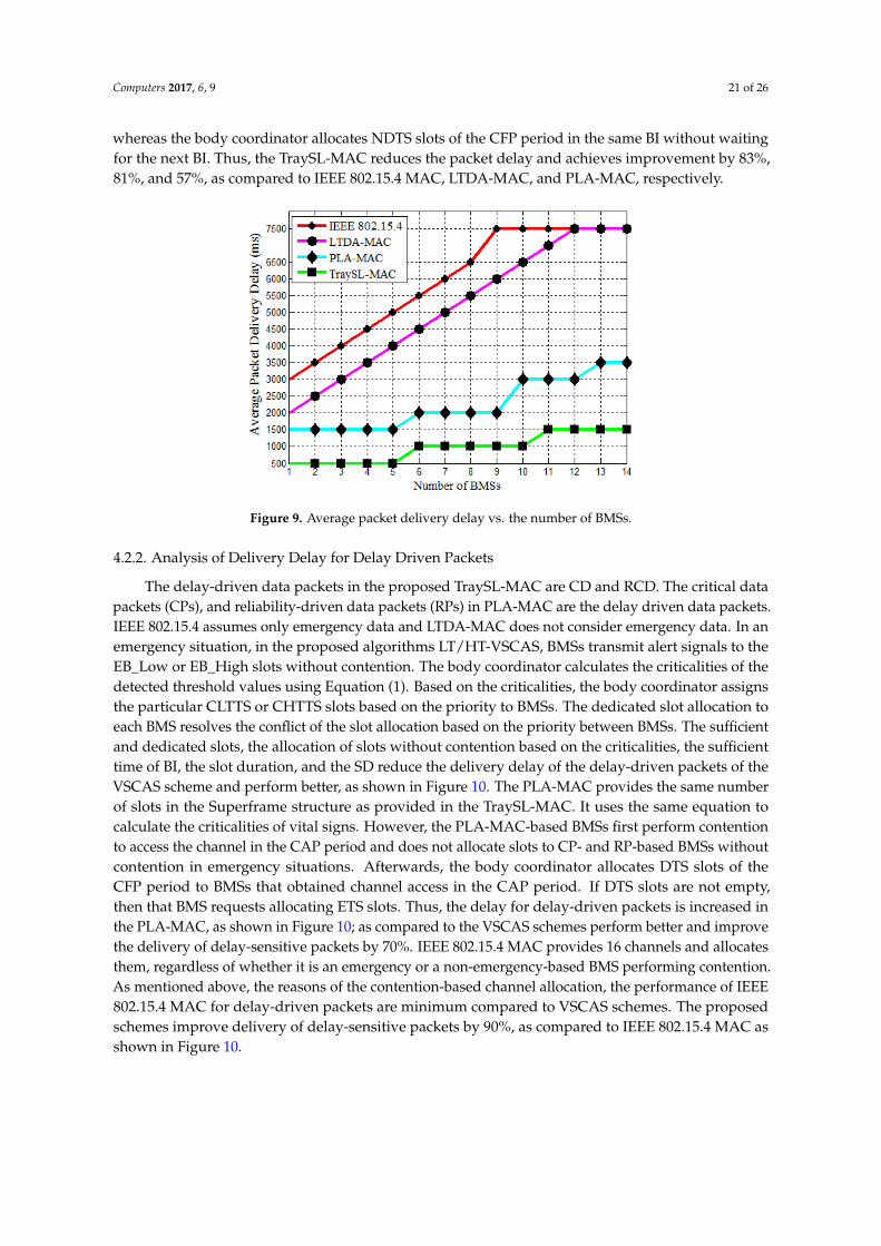
Computers 2017, 6, 9 21 of 26
whereas the body coordinator allocates NDTS slots of the CFP period in the same BI without waitingfor the next BI. Thus, the TraySL-MAC reduces the packet delay and achieves improvement by 83%,81%, and 57%, as compared to IEEE 802.15.4 MAC, LTDA-MAC, and PLA-MAC, respectively.
Computers 2017, 6, 9 21 of 26
achieves improvement by 83%, 81%, and 57%, as compared to IEEE 802.15.4 MAC, LTDA-MAC, and PLA-MAC, respectively.
Figure 9. Average packet delivery delay vs. the number of BMSs.
4.2.2. Analysis of Delivery Delay for Delay Driven Packets
The delay-driven data packets in the proposed TraySL-MAC are CD and RCD. The critical data packets (CPs), and reliability-driven data packets (RPs) in PLA-MAC are the delay driven data packets. IEEE 802.15.4 assumes only emergency data and LTDA-MAC does not consider emergency data. In an emergency situation, in the proposed algorithms LT/HT-VSCAS, BMSs transmit alert signals to the EB_Low or EB_High slots without contention. The body coordinator calculates the criticalities of the detected threshold values using Equation (1). Based on the criticalities, the body coordinator assigns the particular CLTTS or CHTTS slots based on the priority to BMSs. The dedicated slot allocation to each BMS resolves the conflict of the slot allocation based on the priority between BMSs. The sufficient and dedicated slots, the allocation of slots without contention based on the criticalities, the sufficient time of BI, the slot duration, and the SD reduce the delivery delay of the delay-driven packets of the VSCAS scheme and perform better, as shown in Figure 10. The PLA-MAC provides the same number of slots in the Superframe structure as provided in the TraySL-MAC. It uses the same equation to calculate the criticalities of vital signs. However, the PLA-MAC-based BMSs first perform contention to access the channel in the CAP period and does not allocate slots to CP- and RP-based BMSs without contention in emergency situations. Afterwards, the body coordinator allocates DTS slots of the CFP period to BMSs that obtained channel access in the CAP period. If DTS slots are not empty, then that BMS requests allocating ETS slots. Thus, the delay for delay-driven packets is increased in the PLA-MAC, as shown in Figure 10; as compared to the VSCAS schemes perform better and improve the delivery of delay-sensitive packets by 70%. IEEE 802.15.4 MAC provides 16 channels and allocates them, regardless of whether it is an emergency or a non-emergency-based BMS performing contention. As mentioned above, the reasons of the contention-based channel allocation, the performance of IEEE 802.15.4 MAC for delay-driven packets are minimum compared to VSCAS schemes. The proposed schemes improve delivery of delay-sensitive packets by 90%, as compared to IEEE 802.15.4 MAC as shown in Figure 10.
Figure 9. Average packet delivery delay vs. the number of BMSs.
4.2.2. Analysis of Delivery Delay for Delay Driven Packets
The delay-driven data packets in the proposed TraySL-MAC are CD and RCD. The critical datapackets (CPs), and reliability-driven data packets (RPs) in PLA-MAC are the delay driven data packets.IEEE 802.15.4 assumes only emergency data and LTDA-MAC does not consider emergency data. In anemergency situation, in the proposed algorithms LT/HT-VSCAS, BMSs transmit alert signals to theEB_Low or EB_High slots without contention. The body coordinator calculates the criticalities of thedetected threshold values using Equation (1). Based on the criticalities, the body coordinator assignsthe particular CLTTS or CHTTS slots based on the priority to BMSs. The dedicated slot allocation toeach BMS resolves the conflict of the slot allocation based on the priority between BMSs. The sufficientand dedicated slots, the allocation of slots without contention based on the criticalities, the sufficienttime of BI, the slot duration, and the SD reduce the delivery delay of the delay-driven packets of theVSCAS scheme and perform better, as shown in Figure 10. The PLA-MAC provides the same numberof slots in the Superframe structure as provided in the TraySL-MAC. It uses the same equation tocalculate the criticalities of vital signs. However, the PLA-MAC-based BMSs first perform contentionto access the channel in the CAP period and does not allocate slots to CP- and RP-based BMSs withoutcontention in emergency situations. Afterwards, the body coordinator allocates DTS slots of theCFP period to BMSs that obtained channel access in the CAP period. If DTS slots are not empty,then that BMS requests allocating ETS slots. Thus, the delay for delay-driven packets is increased inthe PLA-MAC, as shown in Figure 10; as compared to the VSCAS schemes perform better and improvethe delivery of delay-sensitive packets by 70%. IEEE 802.15.4 MAC provides 16 channels and allocatesthem, regardless of whether it is an emergency or a non-emergency-based BMS performing contention.As mentioned above, the reasons of the contention-based channel allocation, the performance of IEEE802.15.4 MAC for delay-driven packets are minimum compared to VSCAS schemes. The proposedschemes improve delivery of delay-sensitive packets by 90%, as compared to IEEE 802.15.4 MAC asshown in Figure 10.
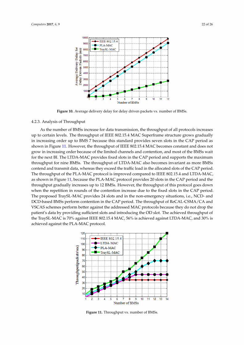
Computers 2017, 6, 9 22 of 26Computers 2017, 6, 9 22 of 26
Figure 10. Average delivery delay for delay driven packets vs. number of BMSs.
4.2.3. Analysis of Throughput
As the number of BMSs increase for data transmission, the throughput of all protocols increases up to certain levels. The throughput of IEEE 802.15.4 MAC Superframe structure grows gradually in increasing order up to BMS 7 because this standard provides seven slots in the CAP period as shown in Figure 11. However, the throughput of IEEE 802.15.4 MAC becomes constant and does not grow in increasing order because of the limited channels and contention, and most of the BMSs wait for the next BI. The LTDA-MAC provides fixed slots in the CAP period and supports the maximum throughput for nine BMSs. The throughput of LTDA-MAC also becomes invariant as more BMSs contend and transmit data, whereas they exceed the traffic load in the allocated slots of the CAP period. The throughput of the PLA-MAC protocol is improved compared to IEEE 802.15.4 and LTDA-MAC, as shown in Figure 11, because the PLA-MAC protocol provides 20 slots in the CAP period and the throughput gradually increases up to 12 BMSs. However, the throughput of this protocol goes down when the repetition in rounds of the contention increase due to the fixed slots in the CAP period. The proposed TraySL-MAC provides 24 slots and in the non-emergency situations, i.e., NCD- and DCD-based BMSs perform contention in the CAP period. The throughput of ReCAL-CSMA/CA and VSCAS schemes perform better against the addressed MAC protocols because they do not drop the patient’s data by providing sufficient slots and introducing the OD slot. The achieved throughput of the TraySL-MAC is 70% against IEEE 802.15.4 MAC, 56% is achieved against LTDA-MAC, and 30% is achieved against the PLA-MAC protocol.
Figure 11. Throughput vs. number of BMSs.
Figure 10. Average delivery delay for delay driven packets vs. number of BMSs.
4.2.3. Analysis of Throughput
As the number of BMSs increase for data transmission, the throughput of all protocols increasesup to certain levels. The throughput of IEEE 802.15.4 MAC Superframe structure grows graduallyin increasing order up to BMS 7 because this standard provides seven slots in the CAP period asshown in Figure 11. However, the throughput of IEEE 802.15.4 MAC becomes constant and does notgrow in increasing order because of the limited channels and contention, and most of the BMSs waitfor the next BI. The LTDA-MAC provides fixed slots in the CAP period and supports the maximumthroughput for nine BMSs. The throughput of LTDA-MAC also becomes invariant as more BMSscontend and transmit data, whereas they exceed the traffic load in the allocated slots of the CAP period.The throughput of the PLA-MAC protocol is improved compared to IEEE 802.15.4 and LTDA-MAC,as shown in Figure 11, because the PLA-MAC protocol provides 20 slots in the CAP period and thethroughput gradually increases up to 12 BMSs. However, the throughput of this protocol goes downwhen the repetition in rounds of the contention increase due to the fixed slots in the CAP period.The proposed TraySL-MAC provides 24 slots and in the non-emergency situations, i.e., NCD- andDCD-based BMSs perform contention in the CAP period. The throughput of ReCAL-CSMA/CA andVSCAS schemes perform better against the addressed MAC protocols because they do not drop thepatient’s data by providing sufficient slots and introducing the OD slot. The achieved throughput ofthe TraySL-MAC is 70% against IEEE 802.15.4 MAC, 56% is achieved against LTDA-MAC, and 30% isachieved against the PLA-MAC protocol.
Computers 2017, 6, 9 22 of 26
Figure 10. Average delivery delay for delay driven packets vs. number of BMSs.
4.2.3. Analysis of Throughput
As the number of BMSs increase for data transmission, the throughput of all protocols increases up to certain levels. The throughput of IEEE 802.15.4 MAC Superframe structure grows gradually in increasing order up to BMS 7 because this standard provides seven slots in the CAP period as shown in Figure 11. However, the throughput of IEEE 802.15.4 MAC becomes constant and does not grow in increasing order because of the limited channels and contention, and most of the BMSs wait for the next BI. The LTDA-MAC provides fixed slots in the CAP period and supports the maximum throughput for nine BMSs. The throughput of LTDA-MAC also becomes invariant as more BMSs contend and transmit data, whereas they exceed the traffic load in the allocated slots of the CAP period. The throughput of the PLA-MAC protocol is improved compared to IEEE 802.15.4 and LTDA-MAC, as shown in Figure 11, because the PLA-MAC protocol provides 20 slots in the CAP period and the throughput gradually increases up to 12 BMSs. However, the throughput of this protocol goes down when the repetition in rounds of the contention increase due to the fixed slots in the CAP period. The proposed TraySL-MAC provides 24 slots and in the non-emergency situations, i.e., NCD- and DCD-based BMSs perform contention in the CAP period. The throughput of ReCAL-CSMA/CA and VSCAS schemes perform better against the addressed MAC protocols because they do not drop the patient’s data by providing sufficient slots and introducing the OD slot. The achieved throughput of the TraySL-MAC is 70% against IEEE 802.15.4 MAC, 56% is achieved against LTDA-MAC, and 30% is achieved against the PLA-MAC protocol.
Figure 11. Throughput vs. number of BMSs. Figure 11. Throughput vs. number of BMSs.
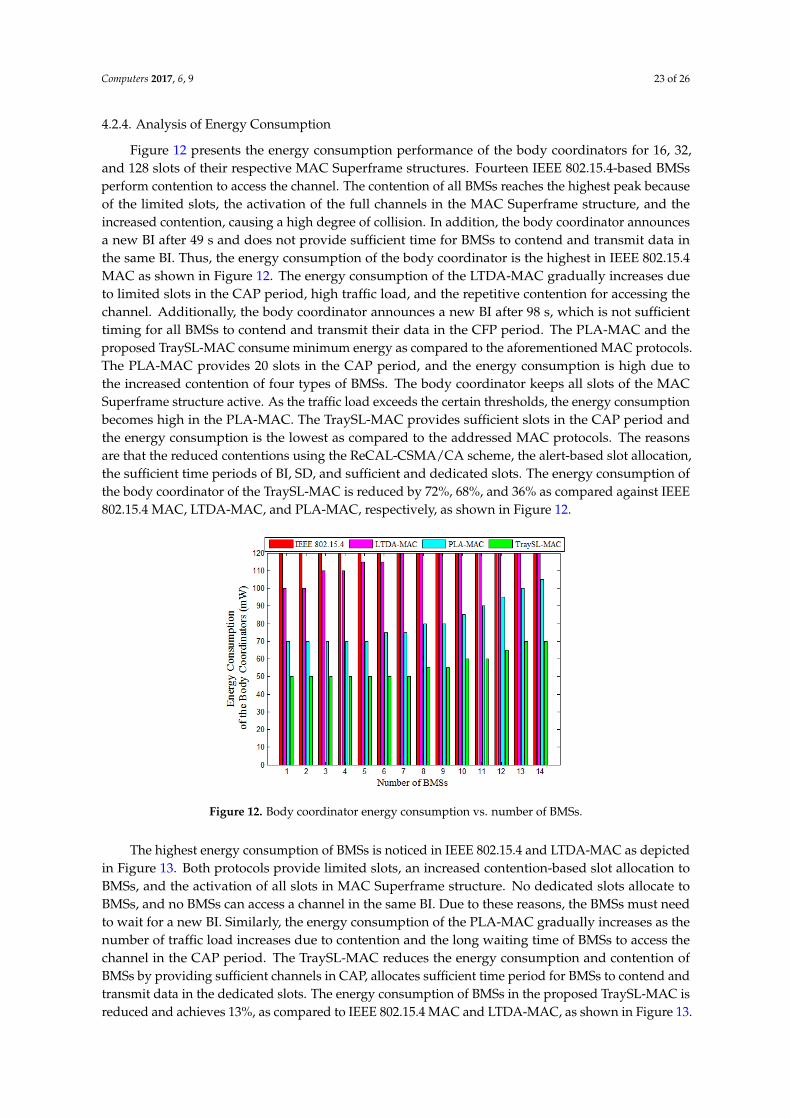
Computers 2017, 6, 9 23 of 26
4.2.4. Analysis of Energy Consumption
Figure 12 presents the energy consumption performance of the body coordinators for 16, 32,and 128 slots of their respective MAC Superframe structures. Fourteen IEEE 802.15.4-based BMSsperform contention to access the channel. The contention of all BMSs reaches the highest peak becauseof the limited slots, the activation of the full channels in the MAC Superframe structure, and theincreased contention, causing a high degree of collision. In addition, the body coordinator announcesa new BI after 49 s and does not provide sufficient time for BMSs to contend and transmit data inthe same BI. Thus, the energy consumption of the body coordinator is the highest in IEEE 802.15.4MAC as shown in Figure 12. The energy consumption of the LTDA-MAC gradually increases dueto limited slots in the CAP period, high traffic load, and the repetitive contention for accessing thechannel. Additionally, the body coordinator announces a new BI after 98 s, which is not sufficienttiming for all BMSs to contend and transmit their data in the CFP period. The PLA-MAC and theproposed TraySL-MAC consume minimum energy as compared to the aforementioned MAC protocols.The PLA-MAC provides 20 slots in the CAP period, and the energy consumption is high due tothe increased contention of four types of BMSs. The body coordinator keeps all slots of the MACSuperframe structure active. As the traffic load exceeds the certain thresholds, the energy consumptionbecomes high in the PLA-MAC. The TraySL-MAC provides sufficient slots in the CAP period andthe energy consumption is the lowest as compared to the addressed MAC protocols. The reasonsare that the reduced contentions using the ReCAL-CSMA/CA scheme, the alert-based slot allocation,the sufficient time periods of BI, SD, and sufficient and dedicated slots. The energy consumption ofthe body coordinator of the TraySL-MAC is reduced by 72%, 68%, and 36% as compared against IEEE802.15.4 MAC, LTDA-MAC, and PLA-MAC, respectively, as shown in Figure 12.Computers 2017, 6, 9 24 of 26
Figure 12. Body coordinator energy consumption vs. number of BMSs.
Figure 13. BMS energy consumption vs. number of BMSs.
5. Conclusions
In this paper, a traffic priority-aware adaptive slot allocation based medium access control protocol has been presented. Three slot allocation algorithms have been developed including a reduced contention adaptive slot allocation, low threshold vital sign criticality-based adaptive slot allocation, and high threshold vital sign criticality-based adaptive slot allocation.
From the design, implementation, and analysis, the following conclusions can be made. TraySL-MAC provides dedicated and sufficient channels along with an adequate period for BI, and avoids channel interference. The repetition in contention rounds of BMSs is reduced by the second algorithm for accessing CAP channels. It also reduces collision, delay, and energy consumption. The slot allocation conflicts among BMSs are resolved via low and high threshold value-based in the send and third algorithms. As compared to the state-of-the-art MAC protocols, the average packet delivery delay is reduced by 73.66%, the average throughput is increased by 52%, and the average energy consumption is minimized by 53%.
Acknowledgments: The research is supported by Ministry of Higher Education Malaysia (MOHE) and conducted in collaboration with Research Management Center (RMC) at University Teknologi Malaysia (UTM) under VOT NUMBER: RJ130000.7828.4F859.
Figure 12. Body coordinator energy consumption vs. number of BMSs.
The highest energy consumption of BMSs is noticed in IEEE 802.15.4 and LTDA-MAC as depictedin Figure 13. Both protocols provide limited slots, an increased contention-based slot allocation toBMSs, and the activation of all slots in MAC Superframe structure. No dedicated slots allocate toBMSs, and no BMSs can access a channel in the same BI. Due to these reasons, the BMSs must needto wait for a new BI. Similarly, the energy consumption of the PLA-MAC gradually increases as thenumber of traffic load increases due to contention and the long waiting time of BMSs to access thechannel in the CAP period. The TraySL-MAC reduces the energy consumption and contention ofBMSs by providing sufficient channels in CAP, allocates sufficient time period for BMSs to contend andtransmit data in the dedicated slots. The energy consumption of BMSs in the proposed TraySL-MAC isreduced and achieves 13%, as compared to IEEE 802.15.4 MAC and LTDA-MAC, as shown in Figure 13.

Computers 2017, 6, 9 24 of 26
As compared to the energy consumption of PLA-MAC, the proposed TraySL-MAC reduces the energyconsumption of BMSs and achieves the improvement of energy consumption by 10%, as shown inFigure 13. These improvements in the energy consumption of BMSs in the proposed solutions are dueto the provision of sufficient channels, the sufficient time period of BI, reduced contention, and theactivation of particular slots.
Computers 2017, 6, 9 24 of 26
Figure 12. Body coordinator energy consumption vs. number of BMSs.
Figure 13. BMS energy consumption vs. number of BMSs.
5. Conclusions
In this paper, a traffic priority-aware adaptive slot allocation based medium access control protocol has been presented. Three slot allocation algorithms have been developed including a reduced contention adaptive slot allocation, low threshold vital sign criticality-based adaptive slot allocation, and high threshold vital sign criticality-based adaptive slot allocation.
From the design, implementation, and analysis, the following conclusions can be made. TraySL-MAC provides dedicated and sufficient channels along with an adequate period for BI, and avoids channel interference. The repetition in contention rounds of BMSs is reduced by the second algorithm for accessing CAP channels. It also reduces collision, delay, and energy consumption. The slot allocation conflicts among BMSs are resolved via low and high threshold value-based in the send and third algorithms. As compared to the state-of-the-art MAC protocols, the average packet delivery delay is reduced by 73.66%, the average throughput is increased by 52%, and the average energy consumption is minimized by 53%.
Acknowledgments: The research is supported by Ministry of Higher Education Malaysia (MOHE) and conducted in collaboration with Research Management Center (RMC) at University Teknologi Malaysia (UTM) under VOT NUMBER: RJ130000.7828.4F859.
Figure 13. BMS energy consumption vs. number of BMSs.
5. Conclusions
In this paper, a traffic priority-aware adaptive slot allocation based medium access control protocolhas been presented. Three slot allocation algorithms have been developed including a reducedcontention adaptive slot allocation, low threshold vital sign criticality-based adaptive slot allocation,and high threshold vital sign criticality-based adaptive slot allocation.
From the design, implementation, and analysis, the following conclusions can be made.TraySL-MAC provides dedicated and sufficient channels along with an adequate period for BI,and avoids channel interference. The repetition in contention rounds of BMSs is reduced by thesecond algorithm for accessing CAP channels. It also reduces collision, delay, and energy consumption.The slot allocation conflicts among BMSs are resolved via low and high threshold value-based in thesend and third algorithms. As compared to the state-of-the-art MAC protocols, the average packetdelivery delay is reduced by 73.66%, the average throughput is increased by 52%, and the averageenergy consumption is minimized by 53%.
Acknowledgments: The research is supported by Ministry of Higher Education Malaysia (MOHE) and conductedin collaboration with Research Management Center (RMC) at University Teknologi Malaysia (UTM) under VOTNUMBER: RJ130000.7828.4F859.
Author Contributions: This research is a group work, and each author has significant contributions. Fasee Ullahcarried out the technical review with suggestions from Abdul Hanan Abdullah and Omprakash Kaiwartya.Marina Md Arshad helped in carrying out revisions of the paper. All authors have read and approved thefinal manuscript.
Conflicts of Interest: The authors declare no conflict of interest.
References
1. Yu, L.; Guo, L.; Deng, H.; Lin, K.; Yu, L.; Gao, W.; Saeed, I.A. Research on Continuous Vital Signs MonitoringBased on WBAN. In Proceedings of the International Conference on Smart Homes and Health Telematics,Wuhan, China, 25–27 May 2016; pp. 371–382.
Computers 2017, 6, 9 25 of 26
2. Chen, M.; Member, S.; Wan, J.; Gonz, S.; Liao, X.; Leung, V.C.M. A Survey of Recent Developments in HomeM2M Networks. IEEE Commun. Surv. Tutor. 2014, 16, 98–114. [CrossRef]
3. Alam, M.M.; Hamida, E.B. Surveying wearable human assistive technology for life and safety criticalapplications: Standards, challenges and opportunities. Sensors 2014, 14, 9153–9209. [CrossRef] [PubMed]
4. Quwaider, M.; Biswas, S. Probabilistic Routing in on-Body Sensor Networks with Postural Disconnections.In Proceedings of the 7th ACM international symposium on Mobility management and wireless access(MobiWAC ’09), Canary Islands, Spain, 27–30 October 2009; pp. 149–158.
5. Chakraborty, C.; Gupta, B.; Ghosh, S.K. Tele-Wound Monitoring through Smartphone. In Proceedings ofthe 2014 International Conference on Medical Imaging, m-Health and Emerging Communication Systems(MedCom), Greater Noida, India, 7–8 November 2014; pp. 197–201.
6. Kumar, P.; Lee, H.-J. Security issues in healthcare applications using wireless medical sensor networks:A survey. Sensors 2012, 12, 55–91. [CrossRef] [PubMed]
7. IEEE 802.15.4. IEEE Standard for Information Technology 802.15.4, Wireless Medium Access Control (MAC) andPhysical Layer (PHY) Specifications for Low-Rate Wireless Personal Area Networks (LR-WPANs); The Institue ofElectrical and Electronics Engineers, Inc.: New York, NY, USA, 2006; Volume 2006.
8. Okdem, S. A real-time noise resilient data link layer mechanism for unslotted IEEE 802.15.4 networks. Int. J.Commun. Syst. 2017, 30, e2955. [CrossRef]
9. Shu, M.; Yuan, D.; Zhang, C.; Wang, Y.; Chen, C. A MAC Protocol for Medical Monitoring Applications ofWireless Body Area Networks. Sensors 2015, 15, 12906–12931. [CrossRef] [PubMed]
10. Anjum, I.; Alam, N.; Razzaque, M.A.; Hassan, M.M.; Alamri, A. Traffic Priority and Load Adaptive MACProtocol for QoS Provisioning in Body Sensor Networks. Int. J. Distrib. Sens. Netw. 2013, 2013, 1–9. [CrossRef]
11. Yoon, J.S.; Ahn, G.-S.; Joo, S.-S.; Lee, M.J. PNP-MAC: Preemptive Slot Allocation and Non-PreemptiveTransmission for Providing QoS in Body Area Networks. In Proceedings of the 2010 7th IEEE ConsumerCommunications and Networking Conference, Las Vegas, NV, USA, 9–12 January 2010; pp. 1–5.
12. Li, C.; Hao, B.; Zhang, K.; Liu, Y.; Li, J. A novel medium access control protocol with low delay and trafficadaptivity for wireless body area networks. J. Med. Syst. 2011, 35, 1265–1275. [CrossRef] [PubMed]
13. Rezvani, S.; Ghorashi, S.A. Context aware and channel-based resource allocation for wireless body areanetworks. IET Wirel. Sens. Syst. 2013, 3, 16–25. [CrossRef]
14. Nepal, S.; Pudasaini, A.; Pyun, J.; Hwang, S.; Lee, C.G.; Shin, S. A New MAC Protocol for EmergencyHandling in Wireless Body Area Networks. In Proceedings of the 2016 Eighth International Conference onUbiquitous and Future Networks (ICUFN), Vienna, Austria, 5–8 July 2016; pp. 588–590.
15. Bhandari, S.; Moh, S. A Priority-Based Adaptive MAC Protocol for Wireless Body Area Networks. Sensors2016, 16, 401. [CrossRef] [PubMed]
16. IEEE 802.11. Available online: http://ieee802.org/11/ (accessed on 17 Octobar 2016).17. IEEE 802.15 WPAN. Available online: http://www.ieee802.org/15/pub/index_TG3e.html (accessed on
26 November 2016).18. Rashwand, S.; Mišic, J. Effects of access phases lengths on performance of IEEE 802.15.6 CSMA/CA.
Comput. Netw. 2012, 56, 2832–2846. [CrossRef]19. Ullah, S.; Higgins, H.; Shen, B.; Kwak, K.S. On the implant communication and MAC protocols for WBAN.
Commun. Syst. 2010, 23, 982–999. [CrossRef]20. Qadri, S.F.; Awan, S.A.; Amjad, M.; Anwar, M.; Shehzad, S. Applications, Challenges, Security of Wireless
Body Area Networks (Wbans) and Functionality of IEEE 802.15.4/ZIGBEE. Sci. Int. Lahore 2013, 25, 697–702.21. Khan, Z.A.; Rasheed, M.B.; Javaid, N.; Robertson, B. Effect of Packet Inter-arrival Time on the Energy
Consumption of Beacon Enabled MAC Protocol for Body Area Networks. Procedia Comput. Sci. 2014, 32,579–586. [CrossRef]
22. Xia, F.; Hao, R.; Li, J.; Xiong, N.; Yang, L.T.; Zhang, Y. Adaptive GTS allocation in IEEE 802.15.4 for real-timewireless sensor networks. J. Syst. Arch. 2013, 59, 1231–1242. [CrossRef]
23. Zhou, J.; Guo, A.; Xu, J.; Su, S. An optimal fuzzy control medium access in wireless body area networks.Neurocomputing 2014, 142, 107–114. [CrossRef]
24. Shuai, J.; Zou, W.; Zhou, Z. Priority-Based Adaptive Timeslot Allocation Scheme for Wireless Body AreaNetwork. In Proceedings of the 2013 13th International Symposium on Communications and InformationTechnologies (ISCIT), Surat Thani, Thailand, 4–6 September 2013; pp. 609–614.

Computers 2017, 6, 9 26 of 26
25. Li, C.; Zhang, B.; Yuan, X.; Ullah, S.; Vasilakos, A.V. MC-MAC: A multi-channel based MAC scheme forinterference mitigation in WBANs. Wirel. Netw. 2016, 1–15. [CrossRef]
26. Yuan, X.; Li, C.; Yang, L.; Yue, W.; Zhang, B.; Ullah, S. A token-based dynamic scheduled MAC protocol forhealth monitoring. EURASIP J. Wirel. Commun. Netw. 2016, 2016, 1–18. [CrossRef]
27. Sarkar, S.; Misra, S. From Micro to Nano: The Evolution of Wireless Sensor-Based Health Care. IEEE Pulse2016, 7, 21–25. [CrossRef] [PubMed]
28. Ullah, S.; Shen, B.; Islam, S.M.R.; Khan, P.; Saleem, S.; Kwak, K.S. A study of MAC protocols for WBANs.Sensors 2010, 10, 128–145. [CrossRef]
29. Naranjo-Hernández, D.; Roa, L.M.; Reina-Tosina, J.; Estudillo-Valderrama, M.A.; Barbarov, G. Low-PowerPlatform and Communications for the Development of Wireless Body Sensor Networks. Int. J. Distrib.Sens. Netw. 2015, 2015, 1–13. [CrossRef]
30. Djenouri, D.; Balasingham, I. New QoS and Geographical Routing in Wireless Biomedical Sensor Networks.In Proceedings of the 6th International ICST Conference on Broadband Communications, Networks,and Systems, Madrid, Spain, 14–16 September 2009; pp. 1–8.
31. Fletcher, G.F.; Ades, P.A.; Kligfield, P.; Arena, R.; Balady, G.J.; Bittner, V.A.; Coke, L.A.; Fleg, J.L.; Forman, D.E.;Gerber, T.C.; et al. Exercise Standards for Testing and Training: A Scientific Statement From the AmericanHeart Association. Circulation 2013, 128, 873–934. [CrossRef] [PubMed]
32. Guazzi, M.; Arena, R.; Halle, M.; Piepoli, M.F.; Myers, J.; Lavie, C.J. 2016 Focused Update: ClinicalRecommendations for Cardiopulmonary Exercise Testing Data Assessment in Specific Patient Populations.Circulation 2016, 133, e694–e711. [CrossRef] [PubMed]
33. WebMD. Counting Respiration Rate. 2016. Available online: http://www.webmd.com/lung/counting-respiration-rate (accessed on 10 Octobar 2016).
34. WikiHow. Breathing Rate (Rate of Respiration). 2016. Available online: http://www.wikihow.com/Check-Someone\T1\textquoterights-Breathing-Rate-(Rate-of-Respiration) (accessed on 2 November 2016).
35. Advisor, N.H. Blood_Pressure_Equation. 2016. Available online: http://www.newhealthadvisor.com/blood-pressure-equation.html (accessed on 25 November 2016).
36. Ready, P.; Steady, P. How various medications affect the blood pressure equation. 2016. Available online:http://cardeneiv.com/c2_cardeneiv_ov_ma.shtml (accessed on 18 December 2016).
37. Tutorvista. Temperature Formula. 2016. Available online: http://formulas.tutorvista.com/physics/temperature-formula.html (accessed on 15 Demeber 2016).
38. WebMD. Body Temperature. 2016. Available online: http://www.webmd.com/first-aid/body-temperature?page=6 (accessed on 18 November 2016).
© 2017 by the authors. Licensee MDPI, Basel, Switzerland. This article is an open accessarticle distributed under the terms and conditions of the Creative Commons Attribution(CC BY) license (http://creativecommons.org/licenses/by/4.0/).