design of an expansion chamber for power tuning of...
TRANSCRIPT
DESIGN OF AN EXPANSION CHAMBER
FOR POWER TUNING OF A TWO STROKE ENGINE
RUDELLE ROLAND RENGGIE
B040410261
4 BMCA
FACULTY OF MECHANICAL ENGINEERING
UNIVERSITI TEKNIKAL MALAYSIA MELAKA (UTeM)
'Saya akui bahawa telah membaca
karya ini dan pada pandangan saya karya
ini adalah memadai dari segi skop dan
kualiti untuk tujuan penganugerahan
Ij azah Sarj ana Muda Kej uruteraan Mekanikal (Automotif)'
Tandatangan .................................
Nama Penyelia Akrnar Abdul Kadir
Tarikh : 13 Mei 2008
DESIGN OF AN EXPANSION CHAMBER
FOR POWER TUNING OF A TWO STROKE ENGINE
RUDELLE ROLAND RENGGIE
B040410261
This report is submitted in partial fulfillment of the requirement for the
Bachelor of Mechanical Engineering (Automotive)
FACULTY OF MECHANICAL ENGINEERING
UNIVERSITI TEKNIKAL MALAYSIA MELAKA (UTeM)
APRIL 2008
DECLARATION
I hereby declare that this project report entitled
DESIGN OF AN EXPANSION CHAMBER
FOR POWER TUNING OF A TWO STROKE ENGINE
is written by me and is my own effort and that no part has been plagiarized without
citations.
SIGNATURE :. . . . .. . . . . . . . . . . . . . . . . . . . . . . . . . . . . &. NAME OF WRITER :.Rudelle Roland Renggie
DATE : 13" May 2008

DEDICATION
Special appreciation dedicated to my parents, Mr & Mrs Roland Renggie Jawa for all
their support throughout this semester. Also, thousands of thanks to my supervisor, Mr
Faizul Akrnar Abdul Kadir for giving me support and motivation while implementing
this project. All the support and encouragement given has become one of the roots for
me in achieving my success.

ACKNOWLEDGEMENT
In general, I hereby would like to express my appreciation to those involved
either directly or indirectly in accomplishing my PSM (2007108). This project would not
have been possible without the support of many peoples. Mr. Faizul Akrnar Abdul
Kadir, my supervisor, deserves a special mention because he has given me all the
support and encouragement throughout this project. And finally, thank goes to my
parents, and numerous friends who have endured this long process with me and always
offer valuable support and love all these while. May all the support and knowledge given
enable me to gain more significant experience and precious understanding on
engineering field in the future.
ABSTRACT
Expansion chamber is an exhaust system used for power tuning in two stroke
engines. The importance of designing appropriate expansion chamber is for power -
tuning in two - stroke engine to ensure the engine to produce more power output with a
reduction of polluted emissions as well. The two stroke engine doesn't utilize an exhaust
stroke or complicated valve to emit the burnt gases fiom cylinder like four stroke engine.
The incoming mixture charge is used to help push the burnt gases out of the exhaust
port. This is not an efficient process since some of the burnt gases remained in the
cylinder and may be some of the new mixture charge escaped through the open exhaust
port. Thus, expansion chamber enhances and controls the flow through the engine by
using pressure pulses. The design of expansion chamber will have an effect on the
pressure movement. The design was based on different cross section and length,
depending on the requirement of the type of engines. Expansion chamber will be
designed using empirical design process. By simulation, results obtained will be used to
verify which expansion chamber gives out the best power performance of two - stroke
engine. Thus, to ensure better engine performance, the design of expansion chamber
must match with the engine specifications.
ABSTRAK
Expansion chamber adalah sistem ekzos yang digunakan untuk menala enjin dua
lejang. Kepentingan merekabentuk expansion chamber yang sesuai adalah untuk
mendapatkan kuasa maksimum pada enjin di samping dapat mengurangkan pengeluaran
hai l pembakaran yang boleh mencemarkan alam sekitar. Enjin dua lejang tidak
mempunyai injap atau lejang ekzos untuk mengeluarkan hasil pembakaran seperti enjin
empat lejang. Maka, carnpuran yang memasuki silinder tersebut akan menolak gas yang
sudah terbakar keluar melalui lubang ekzos. Proses ini kurang efisien kerana masih
terdapat sedikit gas yang sudah terbakar masih menduduki silinder tersebut dan
kemungkinan juga sebilangan daripada campwan yang baru memasuki silinder tadi
keluar melalui lubang ekzos yang terbuka tadi sebelum pembakaran berlaku. Maka,
expansion chamber akan digunakan untuk mengawal aliran yang berlaku di dalam enjin
tersebut dengan mengawal tekanan yang berlaku pada paip sistem ekzos tersebut. Reka
bentuk expansion chamber akan mempengaruhi pergerakan tekanan bendalir tersebut.
Expansion chamber akan direka mengikut diameter dan panjang yang berbeza
bergantung kepada jenis enjin yang diuji mengikut proses empirikal. Expansion chamber
akan diuji melalui dengan kaedah simulasi untuk mengenalpasti expansion chamber
yang akan mendapatkan kuasa paling maksimum pada halaju enjin tertentu yang
dikehendaki. Maka, untuk mendapatkan prestasi dan kuasa maksimum yang dikendaki,
expansion chamber yang direka haruslah menepati specifikasi enjin yang ditetapkan.
CONTENT
CHAPTER SUBJECT
DECLARATION
DEDICATION
ACKNOWLEDGEMENT
ABSTRACK
ABSTRAK
CONTENT
LIST OF TABLE
LIST OF FIGURE
LIST OF SYMBOL
LIST OF APPENDIX
CHAPTER 1 INTRODUCTION
1.1 Background
1.2 Objective
1.3 Scope
1.4 Problem Statement
CHAPTER 2 LITERATURE REVIEW
2.1 Engine Review
2.2 Engine Characteristics
2.3 Two - Stroke Engine
2.3.1 Principles of Two - Stroke Engine
2.4 Introduction to Expansion Chamber
PAGE . . 11
. . . 111
iv
v
vi
vii
xi . . . xlll
xvi
xviii
2.5 The Theoretical Background Of
Tuned Exhaust Pipe on Two - Stroke Engine
2.6 Exhaust Tuning On Two - Stroke Engine
2.7 Performance of Two - Stroke Engine
with an untuned and Tuned Exhaust Pipe
2.8 Motion of Pressure Wave In a Pipe
2.8.1 Bernoulli's Equation
2.8.2 Reflection of Pressure Wave In a
Pipe at an area change
2.9 Influence of Length and Cross Section of
Expansion Chamber in Power Tuning
2.10 Designs for Expansion Chamber
2.10.1 The Exhaust System for an Untuned
Engine
2.10.2 The Exhaust System for High
Performance Engine
CHAPTER 3 METHODOLOGY
3.1 Literature Review
3.2 Problem Statement
3.3 Piping Design
3.4 Method of Testing
3.4.1 Simulation Software
3.5 Result and Data Analysis
3.6 Discussion
CHAPTER 4 PIPING DESIGN
4.1 Engine Specifications
4.2 Common Parameters
4.3 The Exhaust System For An Untuned Engine
4.2.1 Design 1 : Enduro Type
4.2.2 Design 2 : Road Racing Type
4.4 The Exhaust System For High
Performance Engine
4.4.1 Design 3 : Enduro Type
4.4.2 Design 4 : Road Racing Type
4.5 Summary of Design Result
4.5.1 Summary of Design for Untuned
Exhaust System
4.5.2 Summary of Design for Tuned
Exhaust System
CHAPTER 5 SIMULATION SETUP
5.1 Launching GT Project Map
5.2 Importing Templates Into The Project
5.3 Defining Project
5.4 Placing Parts
5.5 Linking Parts
5.6 Run Setup I Case Setup I Plot Setup
5.7 Result GT - Post
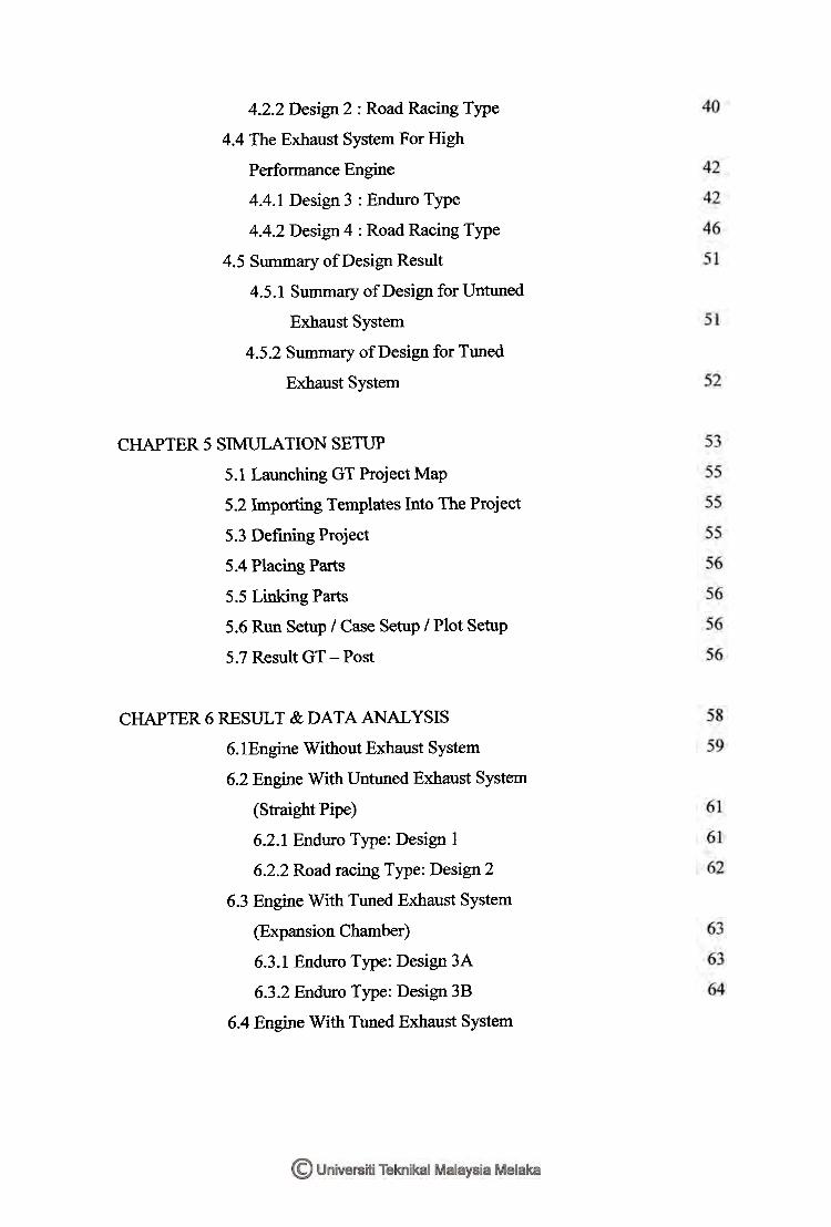
CHAPTER 6 RESULT & DATA ANALYSIS
6.1Engine Without Exhaust System
6.2 Engine With Untuned Exhaust System
(Straight Pipe)
6.2.1 Enduro Type: Design 1
6.2.2 Road racing Type: Design 2
6.3 Engine With Tuned Exhaust System
(Expansion Chamber)
6.3.1 Enduro Type: Design 3A
6.3.2 Enduro Type: Design 3B
6.4 Engine With Tuned Exhaust System
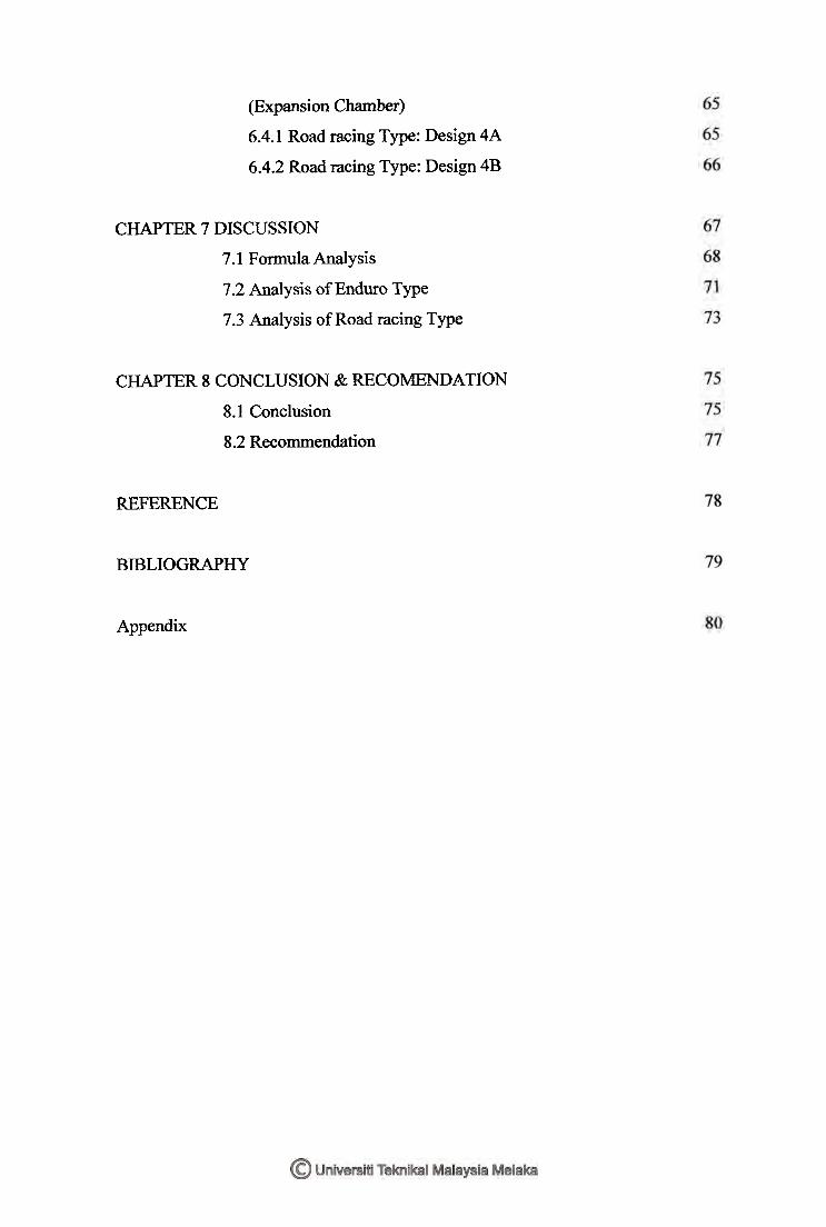
(Expansion Chamber)
6.4.1 Road racing Type: Design 4A
6.4.2 Road racing Type: Design 4B
CHAPTER 7 DISCUSSION
7.1 Formula Analysis
7.2 Analysis of Enduro Type
7.3 Analysis of Road racing Type
CHAPTER 8 CONCLUSION & RECOMENDATION
8.1 Conclusion
8.2 Recommendation
REFERENCE
BIBLIOGRAPHY
Appendix
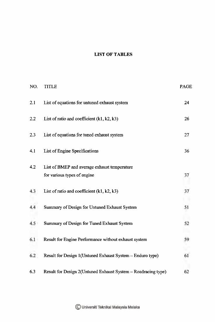
LIST OF TABLES
NO.
2.1
2.2
2.3
4.1
4.2
TITLE
List of equations for untuned exhaust system
List of ratio and coefficient (kl, k2, k3)
List of equations for tuned exhaust system
List of Engine Specifications
List of BMEP and average exhaust temperature
for various types of engine
List of ratio and coefficient (kl, k2, k3)
Summary of Design for Untuned Exhaust System
Summary of Design for Tuned Exhaust System
Result for Engine Performance without exhaust system
Result for Design 1 (Untuned Exhaust System - Enduro type)
6.3 Result for Design 2(Untuned Exhaust System - Roadracing type)
PAGE
24
26
xii
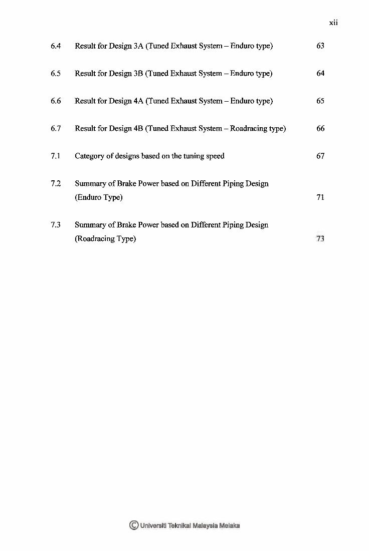
6.4 Result for Design 3A (Tuned Exhaust System - Enduro type) 63
6.5 Result for Design 3B (Tuned Exhaust System - Enduro type) 64
6.6 Result for Design 4A (Tuned Exhaust System - Enduro type) 65
6.7 Result for Design 4B (Tuned Exhaust System - Roadracing type) 66
7.1 Category of designs based on the tuning speed 67
7.2 Summary of Brake Power based on Different Piping Design
(Enduro Type) 71
7.3 Summary of Brake Power based on Different Piping Design
(Roadracing Type)
LIST OF FIGURES
TITLE
Layout of two - stroke engine
Intake process
First stroke process
Compression process
Exhaust blowdown
Sections of an expansion chamber
(Source : http://en.wikipedia.ordwiki/Expansion chamber)
Energy pulse enters the header pipe
Negative pressure wave reflects towards the engine
Positive pressure wave reflected back to the exhaust port
2.1 0 Negative mixture being force into cylinder
PAGE
7
8
9
9
10
Example of convergent section
(Source : h s
The curves show the relationship between pressure,
area and velocity
(Source :
Layout of Expansion Chamber
Flow chart of project implementation
Flow Chart of Design Category
Untuned Exhaust System (Design 1 : Enduro Type)
Untuned Exhaust System (Design 2: Roadracing Type)
Tuned Exhaust System for Enduro type (Design 3A)
Tuned Exhaust System for Enduro type (Design 3B)
Tuned Exhaust System for Road racing type (Design 4A)
Tuned Exhaust System for Road racing type (Design 4B)
Layout of an Expansion Chamber
Flow Chart of Simulation Setup
5.2 Arranging all components in the project map
xiv
19
Creating links between parts
Case RLT Plot of result
Brake Power (kW) vs. Engine Speed (RPM) for engine
without exhaust system
Brake Power (kW) vs. Engine Speed (RPM) for Design 1
Brake Power (kW) vs. Engine Speed (RPM) for Design 2
Brake Power (kW) vs. Engine Speed (RPM) for Design 3A
Brake Power (kW) vs. Engine Speed (RPM) for Design 3B
Brake Power (kW) vs. Engine Speed (RPM) for Design 4A
Brake Power (kW) vs. Engine Speed (RPM) for Design 4B
Actual Tuned Length in an Expansion Chamber
Brake Power (kW) vs. Speed (RPM) for Enduro Type
7.3 Brake Power (kW) vs. Speed (RPM) for Road racing Type
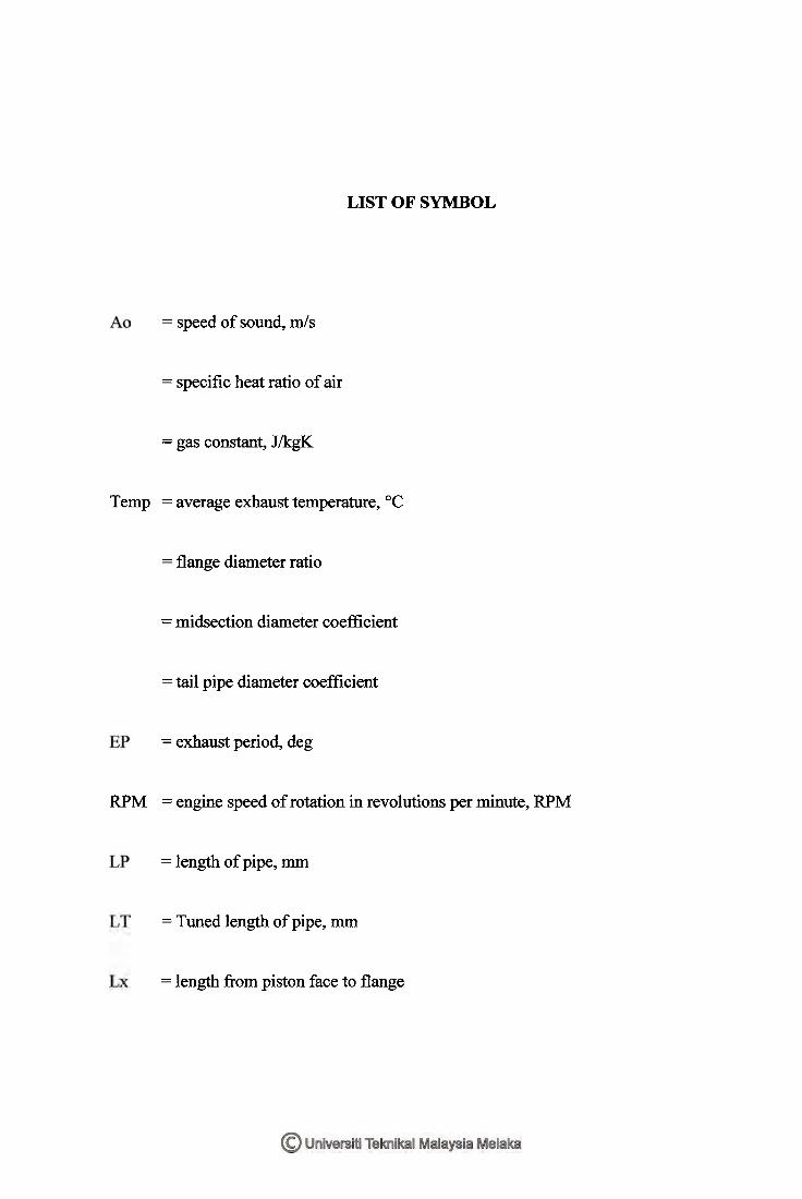
LIST OF SYMBOL
Temp
RPM
= speed of sound, m/s
= specific heat ratio of air
= gas constant, J/kgK
= average exhaust temperature, OC
= flange diameter ratio
= midsection diameter coefficient
= tail pipe diameter coeflicient
= exhaust period, deg
= engine speed of rotation in revolutions per minute, RPM
= length of pipe, mm
= Tuned length of pipe, rnm
= length from piston face to flange
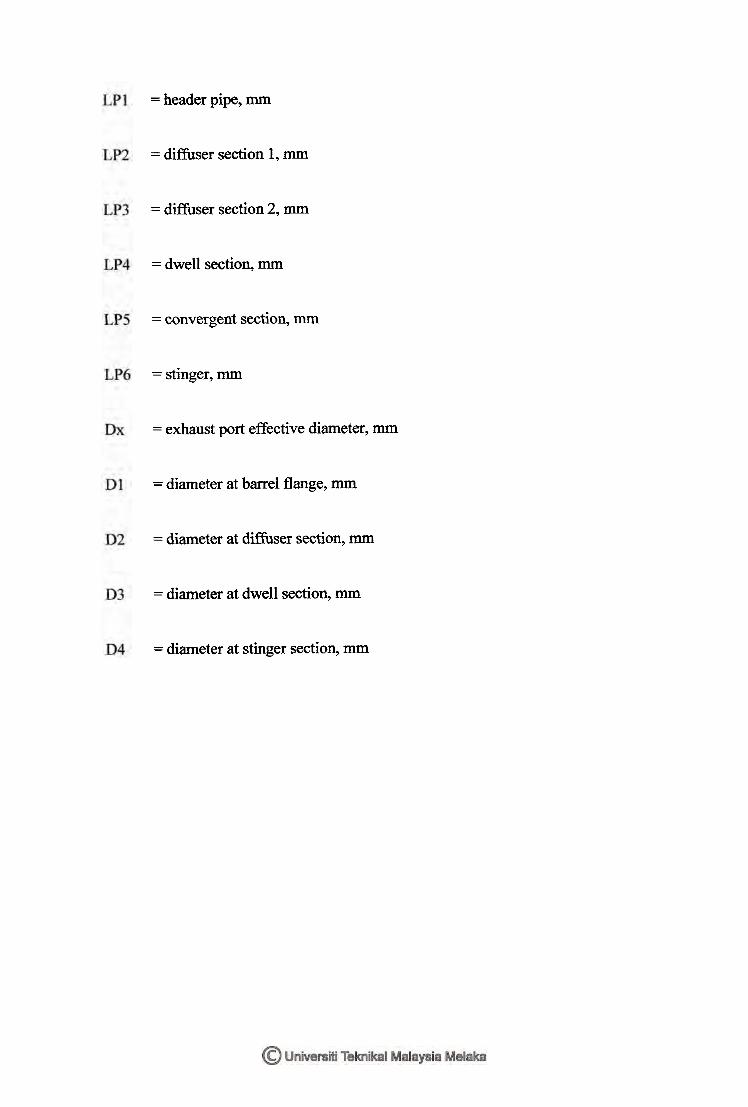
= header pipe, mm
= diffuser section 1, mm
= diffuser section 2, mm
= dwell section, mm
= convergent section, mm
= stinger, rnm
= exhaust port effective diameter, mm
= diameter at barrel flange, mm
= diameter at diffuser section, mm
= diameter at dwell section, mm
= diameter at stinger section, mm
LIST OF APPENDICES
TITLE
Gantt Chart PSM 1
Gantt Chart PSM 2
Design 1 : Untuned Exhaust System (Enduro Type)
Design 2: Untuned Exhaust System (Road Racing Type)
Design 3A: Tuned Exhaust System (Enduro Type)
Design 3B: Tuned Exhaust System (Enduro Type)
Design 4A: Tuned Exhaust System (Road Racing Type)
Design 4B: Tuned Exhaust System (Road Racing Type)
Catia Drawing for Untuned Exhaust System (Straight Pipe)
Catia Drawing for Tuned Exhaust System
Enduro Type (Expansion Chamber)
PAGE
81
82
83
84
85
86
87
88
89

11 Catia Drawing for Tuned Exhaust System (Expansion Chamber)
Road racing Type (Expansion Chamber)
12 Catia Drawing :
Isometric View of Straight Pipe & Expansion Chamber
xix
91
CHAPTER 1
INTRODUCTION
This project involved with the design of an expansion chamber which will be used to
tune a two stroke engine. This is important since constructing an expansion chamber will
ensure that the engine is able to breathe correctly and produce efficient power output.
An expansion chamber is designed by varying its diameter (cross section) and
length. It is used to enhance power output produced by increasing the volumetric
efficiency of the two stroke cycle engine. Volumetric efficiency is the ratio of the
volume of air drawn into a cylinder to the piston displacement.
The performance of two stroke engine will be tested through simulation.
Different sizes of expansion chamber are used during the testing session. Result of the
performance of engine is obtained after modeling an engine and run the simulation by
using GT-Power. The result is used to evaluate at which size of the expansion chamber
will the maximum power is obtained.
1.1 Background
Basically, after completing one revolution for each cycle, burnt gases and fresh mixture
(unburned gases) will suck out fkom the cylinder. These high pressure gases whish exit
through the cylinder initially flows in the form of a wave front and subsequently enter a
pipe called expansion chamber which is already occupied by gas from previous cycle.
The gas from previous cycle will be pushed ahead and this will cause a wave front.
Although the gas flow itself stops, the wave still goes on by passing the energy to the
next down stream until it reaches the end part of the pipe.
However if the wave encounters any changes in cross section or temperature, it
will reflect a part of its strength in the opposite direction it travel which practice the
wave dynamics principles. Thus, expansion chamber will be designed by using this basic
principal since its diameter (cross section) and length are varied as a way to push back
the fiesh mixture back into the cylinder at the desired times in the cylinder.
Good chamber works by giving lots of power over a wide rpm-range. Thus, the
cross section of an expansion chamber influences the power output since the power is
tuned when the reflected wave is out of phase with the primary wave at the exit of the
exhaust valve.
1.2 Objective
The objective of this project is to design an expansion chamber to tune a two stroke
engine in order to obtain maximum power at certain engine speed.
1.3 Scope
These project scopes consist of the following:
as Study on single ~ylinder of two stroke engine.
b. To study and design expansion chamber based on condition required.
c. To conduct simulation on power testing of different sizes of expansion chamber
d. To choose the most suitable expansion chamber on certain engine speed required.
1.4 Problem Statement
In two - stroke internal combustion engine, each outward stroke of the piston is a
power stroke. As a way to achieve this operating cycle, a fresh charge of air and fuel
must be supplied to the engine cylinder at a high pressure to displace the burned gases
from the previous cycle. The combination of process between intake and exhaust process
that clears the cylinder of burned gases and fills it with a fiesh mixture (of air and fuel)
is called scavenging process. This process is essential in having a smooth-running
internal combustion engine.
As the piston moves from top to bottom dead center, uncovering the intake ports,
the burned gases are pushed into the exhaust port by the incoming flow of fiesh mixture
(air and fuel). This is not an efficient process since some of the burnt gases remaining in
the cylinder and some of the fresh air or fuel charge escape through the open exhaust
port. At this point in time, the opening just begins to form, and as a result the flow in the
combustion chamber changes dramatically. As the piston drops down and begin its
return motion back to TDC the burned gases are pushed into the exhaust duct.
Thus, by modifying the exhaust system such as modifling the exhaust gas
velocity (by changing exhaust tube diameters and lengths) it can detract from the "ideal"
scavenging effects, and reduce fuel consumption as well as increase the power output.