computational study of shear strengthened of rc … · 2013-07-18 · penggunaan lajur-lajur cfrp...
TRANSCRIPT

COMPUTATIONAL STUDY OF SHEAR STRENGTHENED OF
RC CONTINUOUS BEAM USING CFRP SHEET WITH
DIFFERENT WRAPPING SCHEME
MHIMED RAMADAN OM BALKOU
UNIVERSITI TUN HUSSEIN ONN MALAYSIA
UNIVERSITI TUN HUSSEIN ONN MALAYSIA
vi
ABSTRAK
Penggunaan Carbon Fiber Reinforced Polymer (CFRP) sebagai tetulang luaran telah
menjadi salah satu penyelesaian alternatif untuk membaikpulih kecacatan ricih pada
struktur konkrit bertetulang. Oleh itu, kajian ini bertujuan untuk mengkaji keberkesanan
penggunaan lajur-lajur CFRP sebagai tetulang luaran bagi menguatkan rasuk selanjar
konkrit bertetulang. Sebanyak lima rasuk selanjar konkrit bertetulang dengan saiz
150x350x5800mm telah disimulasi dan ianya melibatkan orientasi 0/90 darjah bagi lajur
CFRP dan dibalut samada empat sisi atau tiga sisi. Kesemua lima rasuk telah dianalisis
menggunakan perisian ABAQUS. Hasil ujikaji mendapati lajur CFRP sebagai tetulang
luaran dapat meningkatkan kapasiti ricih bagi rasuk selanjar konkrit bertetulang.
Keputusan simulasi juga menunjukkan hasil yang hampir sama dengan keputusan
ujikaji makmal.
vii
CONTENTS
TITLE i
DECLARATION ii
DEDICATION iii
ACKNOWLEDGEMENT iv
ABSTRACT v
ABSTRAK vi
CONTENTS vii
LIST OF TABLES x
LIST OF FIGURES xi
LIST OF SYMBOLS AND ABBREVIATIONS xiv
viii
CHAPTER 1 INTRODUCTION 1
1.1 Problem Statement 1
1.2 Project Objectives 2
1.3 Scope of the study 3
1.4 Significance of the study 4
CHAPTER 2 LITERATURE REVIEW 5
2.1 History of FRP 5
2.2 The types of FRP are 5
2.2.1 Glass fibers 6
2.2.2 Carbon fibers 7
2.2.3 Aramid fibers 7
2.3 Advantages of FRP 8
2.4 Disadvantages of FRP 8
2.5
2.5.1.1
2.6
2.7
2.7.1
2.7.2
Shear strength of Reinforced concrete using FRP
ACI Code provisions for shear strength of Beam
Contribution of FRP to Shear Capacity
Khalifa Model
Shear Capacity of a CFRP Strengthened Section
Reduction coefficient Based on CFRP Sheet
fracture failure
8
9
10
10
10
13
2.7.3 Reduction coefficient Based on Bond Mechanism
Model
2.7.4 Upper limit of the reduction coefficient
2.7.5 Controlled reduction coefficient
2.8 ACI440 models
2.9 Previous researches on shear strengthening using
CFRP
14
15
15
15
17
ix
CHAPTER 3
METHODOLOGY
3.1 Introduction 22
3.2 Methodology process 22
3.3 Interview 23
3.4 Site visit 24
3.5 Questionnaire design 24
3.6 Pilot study 25
3.7 Reliability and validity 26
3.8 Data analysis 27
3.9 Methodology flow chart 28
CHAPTER 4 RESULTS AND DISCUSSION
29
4.1 Introduction 36
4.2 Ultimate Load 36
4.3
4.3.1
Load-Displacement Behaviour
Load-Displacement Behaviour of Beam C2.5-C
37
38
4.3.2 Load-Displacement Behaviour of Beam C2.5-U-V 40
4.3.3 Load-Displacement Behaviour of Beam C2.5-UA-V 41
4.3.4 Load-Displacement Behaviour of beam C2.5-U-V2 42
4.3.5 Load-Displacement Behaviour of Beam C2.5-UA-V2 43
4.4 Load-Longitudinal Reinforcement Strain 44
46dfd44444.5 4.4.1
Load-Longitudinal Reinforcement Behaviour of Beam
C2.5- C
45
4.4.2
Load-Longitudinal Reinforcement Behaviour of Beam
C2.5-U-V
46
4.4.3
Load-Longitudinal Reinforcement Behaviour of C2.5-
UA-V
47
4.4.4 Load-Longitudinal Reinforcement Behaviour of Beam 48
x
C2.5-U-V2
4..4.5
Load-Longitudinal Reinforcement Behaviour of Beam
C2.5-UA-V2
49
4.5.1 Load-Stirrups Strain Behaviour 50
4.5.2 Load-Stirrups Strain Graph for Beam C2.5-U-V 52
CHAPTER 5
4.5.3 Load-Stirrups Strain Graph of Beam C2.5-UA-V
4.5.4 Load-Stirrups Strain Graph of Beam C2.5-U-V2
4.5.5 Load-Stirrups Strain Graph of Beam C2.5-UA-V2
4.6.1 Load-CFRP Behaviour of Beam C2.5-U-V
4.6.2 Load-CFRP Strain Graph of Beam C2.5-UA-V
4.6.3 Load-CFRP Strain Graph of Beam C2.5-U-V2
4.6.4 Load-CFRP Strain Graph of Beam C2.5-UA-V2
4.7.1 Load-Concrete Surface Behaviour
4.7.2 Load-Concrete Surface Strain Graph of C2.5-U-V
4.7.3 Load-Concrete Surface Strain Graph of Beam C2.5-
UA-V
4.7.4 Load-Concrete Surface Strain Graph of Beam C2.5-
U-V2
4.7.5 Load-Concrete Surface Strain Graph of Beam C2.5-
UA-V2
4.8 Discussions
CONCLUSION AND RECOMMANDATION
54
56
58
60
62
64
66
68
70
72
74
76
78
5.1 Introduction 79
5.2 Conclusion
5.2.1 Ultimate Load
5.2.2 Effect of Number of Layer of CFRP Strains
5.2.3 Effect of Wrapping Schame (Three Side and Four
Side Wrapping)
5.3 Recommendation for future research
79
79
80
80
80

xi
REFERENCES
94
APPENDIX A-C 96
xi
LIST OF FIGURES
3.1 Reinforcement details 20
3.2 Cross section details 21
3.3 Loading Position 21
3.4 Cross Section for Fully Wrap (4 sides bonding) 21
3.5 Cross Section for 3 Sides Bonding 22
3.6 Flow chart of FE analysis using ABAQUS 24
3.7 Quratar of beam 25
3.8 Steel reinforcement with stirrups 26
3.9 Enter a file nama as Numerical Analysis of beam 27
3.10 Meshing of the quarter of beam 28
3.11 Defining material propertie 29
3.12 Making the model visible 30
3.13 Apply support in the Y direction at the right of the quarter of beam 31
3.15 Step of assigning load 32
3.16 Applied load 33
3.17 The full complete model of quarter of beam strengthened with CFRP 33
3.18 Viewing the Results 35
4.1 Load vs Mid Deflection of specimens 38
4.2 Comparison for simulation and experimental of Load Mid Deflection
for Control beam (C2.5-C)
39
4.3 Comparison for simulation and experimental of Load Mid Deflection
for C2.5-U-V
40
xii
4.4 Comparison for simulation and experimental of Load Mid Deflection
for C2.5-UA-V.
41
4.5 Comparison for simulation and experimental of load Mid deflection for
C2.5-U-V2.
42
4.6 Comparison for simulation and experimental of load mid deflection for
C2.5-UA-V2
43
4.7 Simulation of load-longitudinal reinforcement strain for five beams 44
4.8 Comparison for simulation and experimental for applied load versus
longitudinal reinforcement strain,ε for C2.5-C
45
4.9 Comparison for simulation and experimental for applied load versus
longitudinal reinforcement strain,ε for beam C2.5-U-V.
46
4.10 Comparison for simulation and experimental for applied Load versus
longitudinal reinforcement strain,ε for beam C2.5-UA-V
47
4.11 Comparison for simulation and experimental for applied load versus
longitudinal reinforcement strain,ε for beam C2.5-U-V2
48
4.12 Comparison for simulation and experimental for applied load versus
longitudinal reinforcement strain,ε for beam C2.5-U2-V2
49
4.13 Comparison for simulation of applied load versu stirrups strain,for
beam C2.5-C (S1,S2,S3,S4)
50
4.14 Comparison for simulation and experimental for applied load versus
stirrups strain, for beam C2.5-C ( S1,S2,S3,S4)
51
4.15 Load versus stirrups strain of specimen (S1,S2.S3.S4) 52
4.16 Comparison for simulation and experimental for applied load versus
stirrups strain, for beam C2.5-U-V (S1, S2, S3, S4)
53
4.17 Load versus stirrups strain,ε of specimen (S1,S2,S3,S4) 54
4.18 Comparison for simulation and experimental for applied load versu
stirrups strain, for beam C2.5-UA-V ( S1,S2,S3,S4).
55
4.19 Load versus stirrups strain of specimen(S1,S,S3,S4) 56
4.20 Comparison for simulation and experimental for applied load versus
stirrups Strain, for beam C2.5-U-V2 ( S1,S2,S3,S4)
57
xiii
4.21 Load versus stirrups strain,ε of specimen (S1,S2,S3,S4) 58
4.22 Comparison for simulation and experimental for applied load versus
stirrups strain, for beam C2.5-UA-V2 ( S1,S2,S3,S4)
59
4.23 Load –CFRP Strain of Specimen (F1,F2,F3,F4) 60
4.24 Comparison for simulation and experimental for applied load versus
strain in CFRP stirrups for beam C2.5-U-V( F1,F2,F3,F4)
61
4.25 Load –CFRP strain of specimen (S1,S2,S3,S4) 62
4.26 Comparison for simulation and experimental for applied load versus
strain in CFRP stirrups for beam C2.5-UA-V (F1, F2, F3, F4)
63
4.27 Load –CFRP strain of specimen (F1,F2,F3,F4) 64
4.28 Comparison for simulation and experimental for applied load versus
strain in CFRP stirrups for beam C2.5-U-V2 (F1, F2, F3, F4).
65
4.29 Load –CFRP strain of specimen(F1,F2,F3,F4) 66
4.30 Comparison for simulation and experimental for applied load versus
strain in CFRP stirrups for beam C2.5-UA-V2 ( F1,F2,F3,F4 ).
67
4.31 Load –Concrete surface strain for specimens (C1, C2, C3, C4) 68
4.32 Comparison for simulation and experimental for applied load –concrete
surface strain for beam C2.5-C (C1, C2, C3, C4)
69
4.33 Load –concrete surface strain of specimens (C1, C2, C3, C4) 70
4.34 Comparison for simulation and experimental for applied load –concrete
surface strain for bean C2.5-U-V (C1, C2, C3, C4)
71
4.35 Load –concrete surface strain for specimens (C1,C2,C3,C4) 72
4.36 Comparison for simulation and experimental for applied load –concrete
surface strain for beam C2.5-UA-V (C1, C2, C3, C4
73
4.37 Load –concrete surface strain for specimens (C1,C2,C3,C4) 74
4.38 Comparsion for simulation and experimental for applied load –concrete
surface strain for beam C2.5-U-V2 (C1, C2, C3.C4)
75
4.39 Load –concrete surface strain for specimens (C1,C2,C3,C4) 76
4.40 Comparison for simulation and experimental for applied load –concrete
surface strain for beam C2.5-UA-V2 (C1, C2, C3.C4)
77
xiv
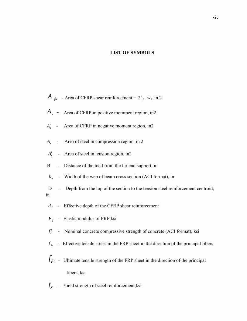
LIST OF SYMBOLS
fsA - Area of CFRP shear reinforcement = ,in 2 ft2 fw
fA - Area of CFRP in positive momment region, in2
fA′
- Area of CFRP in negative moment region, in2
sA - Area of steel in compression region, in 2
- Area of steel in tension region, in2 sA′
B - Distance of the load from the far end support, in
- Width of the web of beam cross section (ACI format), in wb
D - Depth from the top of the section to the tension steel reinforcement centroid, in
- Effective depth of the CFRP shear reinforcement fd
- Elastic modulus of FRP,ksi fE
- Nominal concrete compressive strength of concrete (ACI format), ksi cf ′
- Effective tensile stress in the FRP sheet in the direction of the principal fibers fef
fuf - Ultimate tensile strength of the FRP sheet in the direction of the principal
fibers, ksi
- Yield strength of steel reinforcement,ksi yf
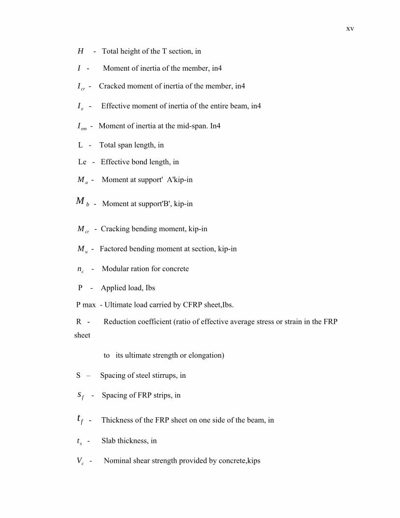
xv
H - Total height of the T section, in
I - Moment of inertia of the member, in4
- Cracked moment of inertia of the member, in4 crI
- Effective moment of inertia of the entire beam, in4 eI
- Moment of inertia at the mid-span. In4 emI
L - Total span length, in
Le - Effective bond length, in
- Moment at support' A'kip-in aM
bM - Moment at support'B', kip-in
- Cracking bending moment, kip-in crM
- Factored bending moment at section, kip-in uM
- Modular ration for concrete cn
P - Applied load, Ibs
P max - Ultimate load carried by CFRP sheet,Ibs.
R - Reduction coefficient (ratio of effective average stress or strain in the FRP
sheet
to its ultimate strength or elongation)
S – Spacing of steel stirrups, in
- Spacing of FRP strips, in fs
- Thickness of the FRP sheet on one side of the beam, in ft
- Slab thickness, in st
- Nominal shear strength provided by concrete,kips cV
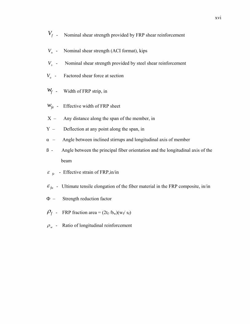
xvi
- Nominal shear strength provided by FRP shear reinforcement fV
- Nominal shear strength (ACI format), kips nV
- Nominal shear strength provided by steel shear reinforcement sV
uV - Factored shear force at section
fw - Width of FRP strip, in
few - Effective width of FRP sheet
X – Any distance along the span of the member, in
Y – Deflection at any point along the span, in
α – Angle between inclined stirrups and longitudinal axis of member
ß - Angle between the principal fiber orientation and the longitudinal axis of the
beam
feε - Effective strain of FRP,in/in
fuε - Ultimate tensile elongation of the fiber material in the FRP composite, in/in
Ф – Strength reduction factor
fρ - FRP fraction area = (2tf /bw)(wf/ sf)
wρ - Ratio of longitudinal reinforcement
x
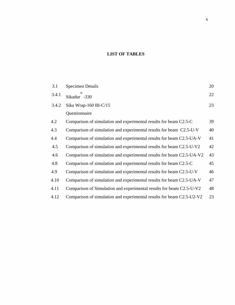
LIST OF TABLES
3.1 Specimen Details 20
3.4.1 Sikadur®
-330 22
3.4.2 Sika Wrap-160 BI-C/15
Questionnaire
23
4.2 Comparison of simulation and experimental results for beam C2.5-C 39
4.3 Comparison of simulation and experimental results for beam C2.5-U-V 40
4.4 Comparison of simulation and experimental results for beam C2.5-UA-V 41
4.5 Comparison of simulation and experimental results for beam C2.5-U-V2 42
4.6 Comparison of simulation and experimental results for beam C2.5-UA-V2 43
4.8 Comparison of simulation and experimental results for beam C2.5-C 45
4.9 Comparison of simulation and experimental results for beam C2.5-U-V 46
4.10 Comparison of simulation and experimental results for beam C2.5-UA-V 47
4.11 Comparison of Simulation and experimental results for beam C2.5-U-V2 48
4.12 Comparison of simulation and experimental results for beam C2.5-U2-V2 23
1
CHAPTER 1
1.0 Introduction.
Many of the existing reinforced concrete (RC), steel, and masonry structures throughout
the world are in urgent need of repair or reconstruction because of deterioration due to
corrosion of their steel reinforcements, various environmental factors, seismic loading,
an increase in service loads, and/ or growing amount of traffic. Moreover, during the
modernization of buildings, the removal of individual supports and walls may lead to a
redistribution of forces and the need for strengthening of structures. Fiber reinforced
polymer (FRP) rebar have been the subject of a significant amount of research in
current years. Researchers have found that one of the major drawbacks to FRP
reinforcement is their brittle failure at ultimate tensile strength. When FRP
reinforcement is used as reinforcement in concrete, sudden failure of the reinforcement
bars can lead to brittle structural failures (Nabila, 2001).
Strengthening of reinforced concrete structures using externally bonded carbon
FRP sheets is an effective method of improving the structural performance under both
service load and ultimate load. Strengthening with externally bonded FRP sheets has
been shown to be applicable to many types of RC structures. Currently, this method has
been implemented to strengthen such structures as columns, beams, slabs, walls,
chimneys, tunnels, and silos. The uses of external FRP reinforcement may be generally
classified as flexural strengthening, improving the confinement and ductility of
compression members and shear strengthening (Khalifa, 1999)
2
1.1 Problem statement
For many years concrete has been used as a preferred material in many structures
including buildings, bridges, pavements, sewer and storm pipes, liquid holding tanks
and others. Shear collapse of reinforced concrete (RC) members is catastrophic and
occurs suddenly with no advance warning of distress. In several occasions existing RC
beams have been found to be deficient in shear and in need of strengthening (Khalifa
1999).
Conventional shear strengthening methods such as external post tensioning, member
enlargement along with internal transverse steel, and bonded steel plates are very costly,
requiring extensive equipment, time, and significant labor. The aging infrastructure
worldwide has prompted many researchers and organizations to seek and techniques to
revive the deteriorating and deficient structures. Advanced composite materials, known
as fiber reinforced polymer (FRP) composites, have received significant attention as one
of the most promising materials for use as external reinforcement in repair and
strengthening of reinforced concrete (RC) structures. Also fiber reinforced polymer
(FRP) composites offers significant advantages such as flexibility in design, ease of
installation, reduced construction time, and improved durability. ( Feras 2007)
1.2 Research objectives
The overall objective of this study program will to investigate the shear performance
and modes of failure of RC beams after strengthening with externally bonded carbon
FRP (CFRP) sheets .More specific objectives were to:
1) To investigate the effectiveness of using externally bonded CFRP strips in repair
RC continuous beams.
3
2) To study the behavior of RC continuous beams repair with CFRP strips wrapping
schemes (4 sides bonding and 3 sides bonding) for initially strengthened
3) To compare the experimental results of repair continuous beams using CFRP
strips with computational study using finite element modeling.
1.3 Scope of Research
The research scopes of this study are as following:
1) This study involves an experimental work and computational study on five RC
continuous beams with identical size of 150 x 350 x 5800 mm.
2) All beams have an identical reinforcement details including stirrups and
longitudinal reinforcement.
3) All beams were design to fails in shear.
4) The type of FRP will be used is bidirectional CFRP sheet.
5) The compressive strength of the concrete is 30 N/ mm2.
6) ABAQUS will be used to analyses all data and will be compared with the
experimental study.
1.4 Significance of Study
Shear collapse of reinforced concrete (RC) members is catastrophic and occurs
suddenly with no advance warning of distress. In several occasions, existing RC beams
have been found to be deficient in shear and in need of strengthening (Jayabrakash,
2006). The previous specific goals were to address the factors affecting the shear
strength, and to propose a design approach for computing the shear capacity of the
strengthened beams. Conversely, the relatively new alternative strengthening technique

4
using advanced composite materials, known as fiber reinforced polymer (FRP), offers
significant advantages such as flexibility in design, ease of installation, reduced
construction time, and improved durability.
CHAPTER 2
LITERATURE REVIEW
2.1 History of FRP
The development of FRP rebar can be traced to the expanded use of composites in the
post World War II era (ACI, 2001). The lightweight, high-strength characteristics
quickly made the material popular in the aerospace industry. In the 1950’s and 1960’s,
the United States, the former Soviet Union, and the United Kingdom were undertaking
research projects to more broadly implement the use of FRP.With the expansion of the
national highway system in the United States and the subsequent use of de-icing salts,
corrosion of the reinforcing steel in pavements exposed to de-icing salts and marine
water began to manifest itself as a problem.FRP reinforcement was not considered a
viable alternative nor was it commercially available until the late 1970’s. The first
solutions to the corrosion of pavement reinforcement were galvanized coatings, powder
resin coatings, polymer-impregnated concrete, epoxy coatings, and GFRP rebar.
Technologically, in the 1980’s, the demand for nonmetallic reinforcement has
increased.
Due to its non-conductive and magnetically transparent characteristics, FRP
reinforcement began to be used in concrete surrounding MRI equipment. During the
6
1990’s, the deterioration of aging bridges in the United States and discovery of
corrosion in some commonly used epoxy coated rebar again brought FRP reinforcement
to the attention of the design and research communities as a possible solution to
corrosion problems of reinforced pavements (ACI, 2001) (Vellore S , 2007).
2.2 The types of FRP are
2.2.1 Glass fibers
These are fibers commonly used in the naval and industrial fields to produce composites
of medium high performance. Their peculiar characteristic is their high strength. Glass
fibers typically have a Young modulus of elasticity (70 GPa for E-glass) lower than
carbon or armed fibers and their abrasion resistance is relatively poor. In addition, a
glass fiber has low fatigue strength.. To enhance the bond between fibers and matrix, as
well as to protect the fibers and moisture, fibers undergo sizing treatments acting as
coupling. Such treatments are useful to enhance durability and fatigue performance
(static and dynamic) of the composite material. FRP composites based on fiberglass are
usually denoted as CFRP (Liu 2007).
2.2.2 Carbon fibers
Carbon fibers are used for their high performance and are characterized by high Young
modulus of elasticity as well as high strength. They have an intrinsically brittle failure
behavior with a relatively low energy absorption; nevertheless, their failure strength are
larger compared to glass and armed fibers. Carbon fibers are less sensitive to creep
7
rupture and fatigue and show a slight reduction of the long-term tensile strength. FRP
composites based on carbon fibers are usually denoted as CFRP.
2.2.3 Aramid fibers
Aramid fibers are organic fibers, made of aromatic polyamides in an extremely orient
form. Due to the anisotropy of the fiber structure, compression loads promote a
localized yielding of the fibers resulting in fiber instability and formation of kinks.
Aramid fibers may degrade after extensive exposure to sunlight, losing up to 50 % of
their tensile strength. In addition, they may be sensitive to moisture. Their creep
behavior is similar to that of glass fibers, even though their failure strength and fatigue
behavior is higher than CFRP. FRP composites based on aramid fibers are usually
denoted as CFRP. For strengthening purposes in civil engineering carbon fibers are the
most suitable (Liu 2007).
2.3 Advantages of FRP
The advantages of FRP are:
1- Reduced construction time.
2- Corrosion resistance.
3- Flexibility in design.
4- High durability.
5- Ease of installation.
6- High strength-to-weight ratio.
7- High longitudinal tensile strength (Carlo Pellegrino 2009).
8
2.4 Disadvantages of FRP
The disadvantages of FRP are:
1- FRP reinforcing composites are typically brittle materials.
2- The ultimate tensile strength of FRP reinforcing bars decreases with bar diameter.
3- Theoretical methods are not currently available to predict the bond properties and
durability characteristics of FRP rebar with convenient accuracy.
4- FRP rebars can be used at service temperatures below the glass transition
temperature of the polymer resin system utilized in the bar.
5- New unfamiliar failure mechanisms are possible particularly in FRP plate bonding
and specialist survey should be provided (Carlo Pellegrino 2009).
2.5 Shear strength of Reinforced concrete using FRP
Shear failure of reinforced concrete RC beams is catastrophic and could occur without
any forewarning. Many of the existing reinforced concrete (RC), and masonry
structures throughout the world are in urgent need of repair or reconstruction because of
deterioration due to corrosion of their steel reinforcements, insufficient shear
reinforcement resulting, design errors, use of outdate codes, increase in demand of
service load, and construction defects and design faults .
The application of Carbon Fiber Reinforced polymer Composite material, as an
external reinforcement is a viable technology recently found to be worth for improving
the structural performance of reinforced concrete structures (Chu kia wang, sixth edition
,1998)
9
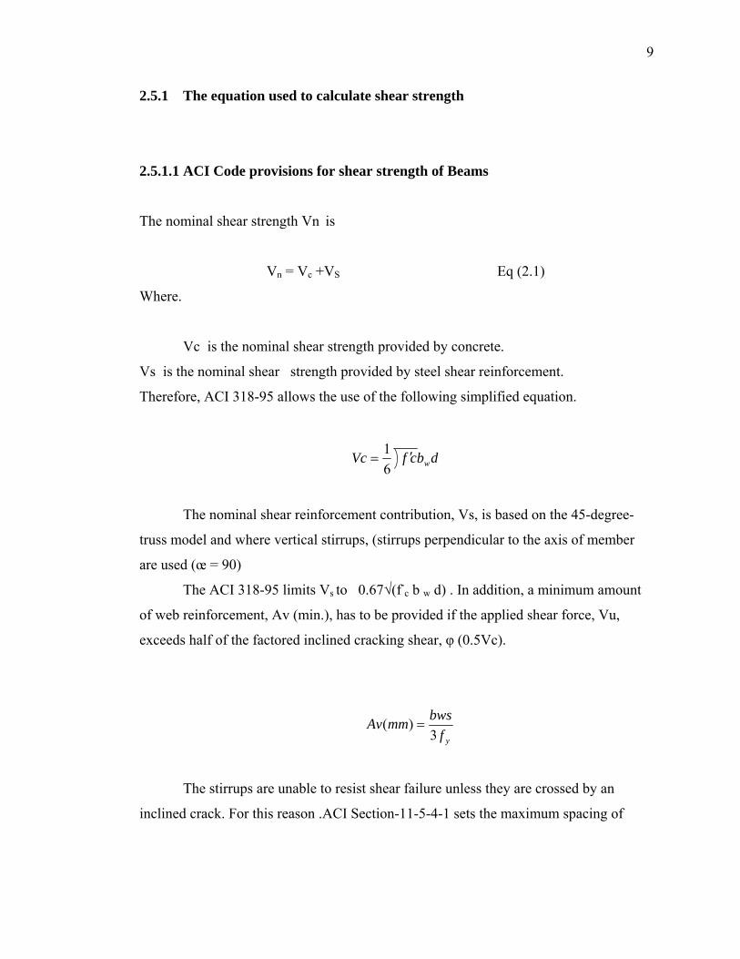
2.5.1 The equation used to calculate shear strength
2.5.1.1 ACI Code provisions for shear strength of Beams
The nominal shear strength Vn is
Vn = Vc +VS Eq (2.1)
Where.
Vc is the nominal shear strength provided by concrete.
Vs is the nominal shear strength provided by steel shear reinforcement. Therefore, ACI 318-95 allows the use of the following simplified equation.
dbcfVc w′=61
The nominal shear reinforcement contribution, Vs, is based on the 45-degree-
truss model and where vertical stirrups, (stirrups perpendicular to the axis of member
are used (œ = 90)
The ACI 318-95 limits Vs to 0.67√(f-c b w d) . In addition, a minimum amount
of web reinforcement, Av (min.), has to be provided if the applied shear force, Vu,
exceeds half of the factored inclined cracking shear, φ (0.5Vc).
yfbwsmmAv3
)( =
The stirrups are unable to resist shear failure unless they are crossed by an
inclined crack. For this reason .ACI Section-11-5-4-1 sets the maximum spacing of
10
vertical stirrups as the smaller. When d/2 or 610 mm if Vs fc' b w d) and when
d/4 or 305 mm if Vs > 'c b w d (Chu kia wang, sixth edition ,1998)
2.6 Contribution of FRP to Shear Capacity
Factors affecting the contribution of FRP to shear capacity.
1- Type of FRP, and its unidirectional rigidity.
2- Amount and distribution of FRP reinforcement.
3- Fiber orientation.
4- Presence of FRP end anchor.
5- Concrete strength.
6- Concrete surface preparation and surface roughness.
7- Steel shear reinforcement index.
8- Loads and support conditions (i.e., shear strengthening in negative or positive
Moment regions).
9- Shear span-to-depth ratio. (Khalifa 1999)
2.7 Khalifa Model
2.7.1 Shear Capacity of a CFRP Strengthened Section
The nominal shear strength of an RC section (Vn) is expressed in Equation (2.1).
Vn = Vc +V s + Vf (2.1)
11
Where:
V f is the shear contribution of the CFRP, Vs is the shear strength of the steel
reinforcement and V c is the shear strength of the concrete.
( )⎟⎟⎠
⎞⎜⎜⎝
⎛−≤
+= s
wc
f
ffeff V
dbfs
dfAV
3'2cossin ββ
Eq. (2. 2)
fd = effective depth of the CFRP shear reinforcement (usually equal to d for
rectangular sections and d-ts for T-sections).
ffe the effective CFRP stress.
fA = area of CFRP shear reinforcement = ff wt2
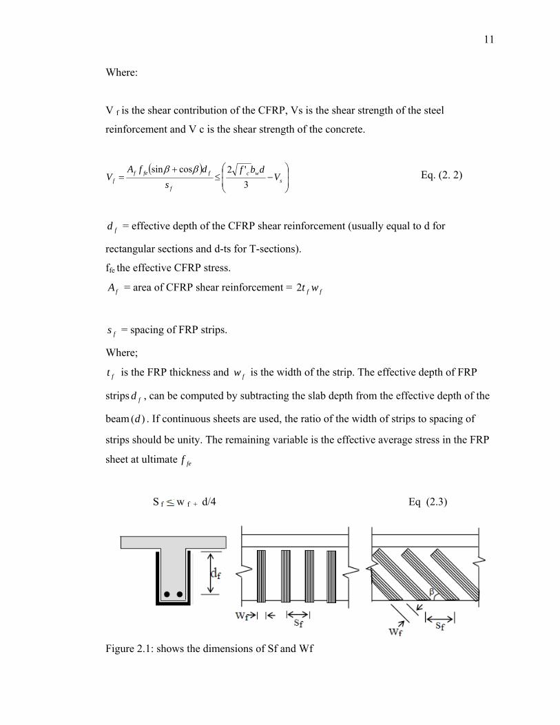
fs = spacing of FRP strips.
Where;
ft is the FRP thickness and is the width of the strip. The effective depth of FRP
strips , can be computed by subtracting the slab depth from the effective depth of the
beam . If continuous sheets are used, the ratio of the width of strips to spacing of
strips should be unity. The remaining variable is the effective average stress in the FRP
sheet at ultimate
fw
fd
)(d
fef
S f w f + d/4 Eq (2.3)
Figure 2.1: shows the dimensions of Sf and Wf
12
Eq. (2. 4) fufe Rff =
Where;
R is reduction coefficient.
fuf = ultimate tensile strength of FRP sheet in direction of principal fibers.
Since the FRP is linearly elastic until failure, the effective strain feε at ultimate limit
state can be computed as follows.
fufe R εε = Eq. (2. 5)
Where:
feε = the effective FRP strain
fuε = ultimate tensile elongation of the fiber material in the FRP composite
Equation (2.3) may be rewritten as follows.
fwfefff dbEV )cos(sin ββερ += Eq. (2. 6)
Where:
fV = nominal shear strength provided by FRP shear reinforcement
fρ = FRP shear reinforcement ratio = )()2
(f
f
w
f
sw
bt
fE = elastic modulus of FRP (GPa)
13
feε = the effective FRP strain
wb = width of the beam cross section
β = angle between the principal fiber orientation and the longitudinal axis of the beam.
Where.
⎟⎟⎠
⎞⎜⎜⎝
⎛==
f
f
w
f
fw
ff S
Wbt
sbA 2
ρ Eq. (2.7)
In the case of continuous wrap
⎟⎟⎠
⎞⎜⎜⎝
⎛= 1
f
f
SW
Eq. (2.8)
2.7.2 Reduction coefficient Based on CFRP Sheet fracture failure
Khalifa has proposed a modification to Triantafillou effective strain model equation
(2.5), (2.6) to determine the reduction coefficient R for the CFRP fracture failure.
Pf Ef 1.1 Gpa
R = 0.5622 (pf Ef) 2- 1.2188 (Pf Ef) + 0.778 (2.9)
The Eq (2.9) M is valid for < 0.7Gpa ff Eρ
14
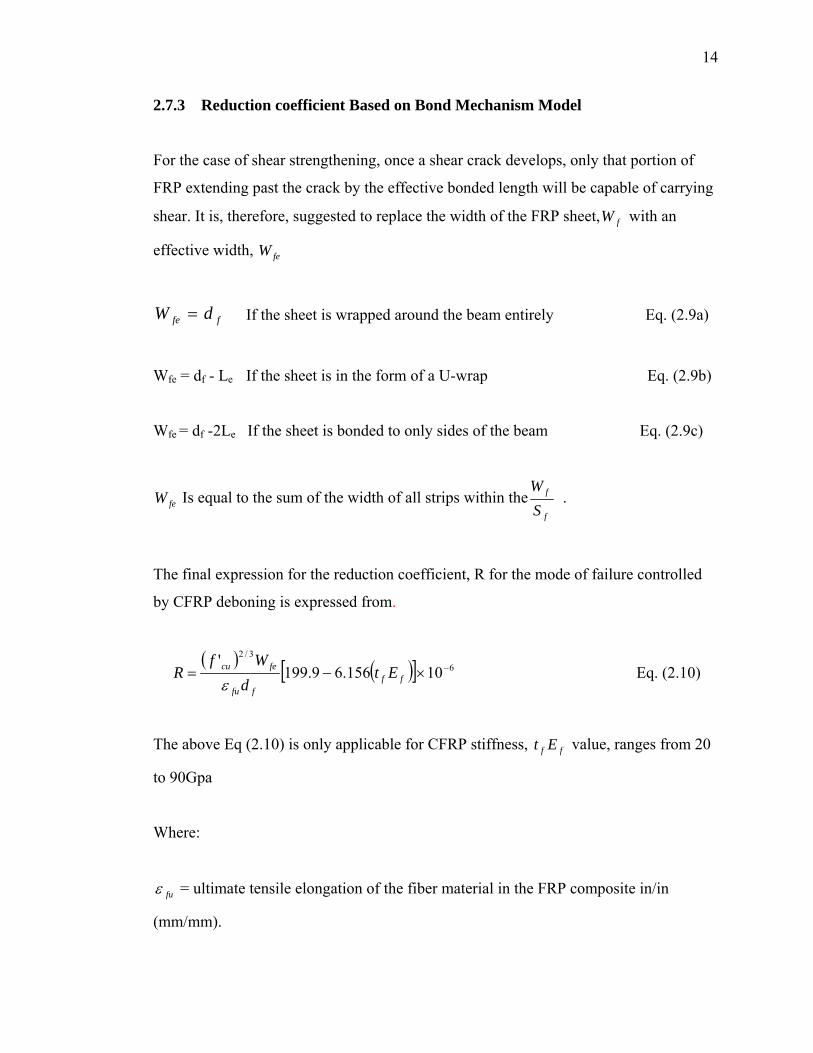
2.7.3 Reduction coefficient Based on Bond Mechanism Model
For the case of shear strengthening, once a shear crack develops, only that portion of
FRP extending past the crack by the effective bonded length will be capable of carrying
shear. It is, therefore, suggested to replace the width of the FRP sheet, with an
effective width,
fW
feW
ffe dW = If the sheet is wrapped around the beam entirely Eq. (2.9a)
Wfe = df - Le If the sheet is in the form of a U-wrap Eq. (2.9b)
Wfe = df -2Le If the sheet is bonded to only sides of the beam Eq. (2.9c)
feW Is equal to the sum of the width of all strips within thef
f
SW
.
The final expression for the reduction coefficient, R for the mode of failure controlled
by CFRP deboning is expressed from.
( ) ( )[ 63/2
10156.69.199' −×−= ff
ffu
fecu Etd
WfR
ε] Eq. (2.10)
The above Eq (2.10) is only applicable for CFRP stiffness, value, ranges from 20
to 90Gpa
ff Et
Where:
fuε = ultimate tensile elongation of the fiber material in the FRP composite in/in
(mm/mm).
15
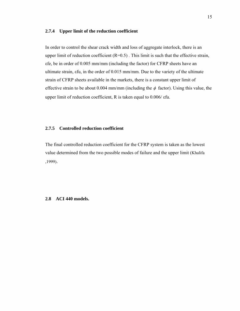
2.7.4 Upper limit of the reduction coefficient
In order to control the shear crack width and loss of aggregate interlock, there is an
upper limit of reduction coefficient (R=0.5) . This limit is such that the effective strain,
εfe, be in order of 0.005 mm/mm (including the factor) for CFRP sheets have an
ultimate strain, εfu, in the order of 0.015 mm/mm. Due to the variety of the ultimate
strain of CFRP sheets available in the markets, there is a constant upper limit of
effective strain to be about 0.004 mm/mm (including the φ factor). Using this value, the
upper limit of reduction coefficient, R is taken equal to 0.006/ εfu.
2.7.5 Controlled reduction coefficient
The final controlled reduction coefficient for the CFRP system is taken as the lowest
value determined from the two possible modes of failure and the upper limit (Khalifa
,1999).
2.8 ACI 440 models.
16
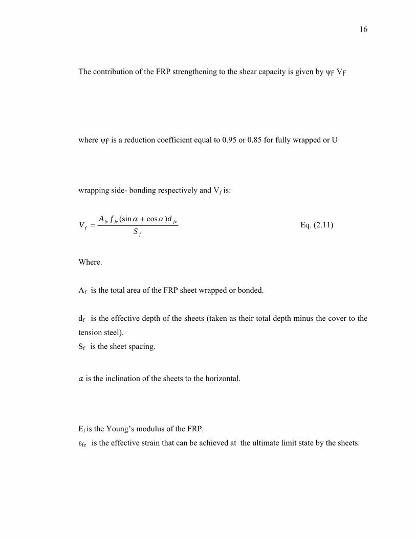
The contribution of the FRP strengthening to the shear capacity is given by ψ V
where ψ is a reduction coefficient equal to 0.95 or 0.85 for fully wrapped or U
wrapping side- bonding respectively and Vƒ is:
f
fvfefvf S
dfAV
)cos(sin αα += Eq. (2.11)
Where.
Af is the total area of the FRP sheet wrapped or bonded.
df is the effective depth of the sheets (taken as their total depth minus the cover to the
tension steel).
Sf is the sheet spacing.
is the inclination of the sheets to the horizontal.
Ef is the Young’s modulus of the FRP.
εfe is the effective strain that can be achieved at the ultimate limit state by the sheets.
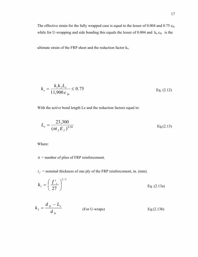
17
The effective strain for the fully wrapped case is equal to the lesser of 0.004 and 0.75 εfu
while for U-wrapping and side bonding this equals the lesser of 0.004 and ku εfu is the
ultimate strain of the FRP sheet and the reduction factor k .
75.0900,11
21 ≤=fu
ev
Lkkkε
Eq. (2.12)
With the active bond length Le and the reduction factors equal to:
58.0)(300,23
ffe Ent
L =
Eq.(2.13)
Where:
n = number of plies of FRP reinforcement.
ft = nominal thickness of one ply of the FRP reinforcement, in. (mm).
3/2
1 27'⎟⎠⎞
⎜⎝⎛= cfk
Eq. (2.13a)
fv
efv
dLd
k−
=2 (For U-wraps) Eq.(2.13b)
18
fv
efv
dLd
k2
2
−=
(For two sides bonded) Eq. (2.13c)
The spacing of the FRP sheets should comply with the limits for stirrups given in ACI
318-08 (2008), and the total shear reinforcement Vs +Vf should not exceed
0.66 fc bwd, (ACI 440.2R, 2008)
2.9 Previous researches on shear strengthening using CFRP
H.K.L.Lee et al.( 2008) is implemented the finite element FE program ABAQUS to
model CFRP strips/sheets. The predicted results are compared with experiment data
(Khalifa and Nanni 2002) to assess the accuracy of the proposed FE analysis approach.
A series of numerical tests were conducted to investigate the influence of stirrup lay-ups
on the shear strengthening performance of the CFRP strips/sheets, to illustrate the
influence of the damage parameters on the micro crack density evolution in concrete,
and to investigate the shear and flexural strengthening performance of CFRP strips/
sheets. It has been shown that the proposed FE analysis approach is suitable for the
performance prediction of RC beams strengthened with CFRP strips/sheets.
Tom Norris, et al (1997) carried out a study on the unretrofitted RC beam
designated as control beam and RC beams retrofitted using carbon fiber reinforced
plastic (CFRP) composites with ±450 and 900 fiber orientations. The effect of
retrofitting on uncracked and precracked beams was studied by using the ANSYS finite
element program. The numerical results shows good agreement with the experimental
values reported.
Mohammed S et al (2009) presented a study of reinforced concrete beams
externally reinforced with fiber reinforced polymer (FRP) laminates using finite
elements method adopted by ANSYS. The finite element models were developed using
a smeared cracking approach for concrete and three dimensional layered elements for
19
the FRP composites. The results obtained from the ANSYS finite element analysis are
compared with the experimental data for six beams with different conditions from
researches (all beams are deficient shear reinforcement) .The accuracy of the finite
element models is assessed by comparison with the experimental results, which are to
be in good agreement. but the finite elements results are slightly stiffer than that from
the experimental results. The maximum difference in ultimate loads for all cases is
7.8%.
CHAPTER 3
METHODOLOGY
3.1 Introduction
The first step of the study was identifying research problem which covered the
significance, objective and scope of study followed by research of the literature.
Information was gathered through sources such as through journals, books, reports and
previous researches. The FE program of this study was done by using ABAQUS. This
chapter will discuss about the specimens details which is consist of five beams and the
details of each beam. This chapter also includes the material properties and explanation
about the method of data analysis which was analyzed by using FE program ABAQUS.
3.2 Specimen Details
This section discusses about the specimens details of the beams. This study involve a
computational study of five continuous beams as shown in the Table 3.1 .Beam No.1 is
beam which not strengthen with CFRP and taken as the control specimen. For beam
No.2, it was wrapped with 3 sides of CFRP strips while for beam No.3, it was wrapped
with 4 sides of CFRP strips. Beam No.4 and 5 have the same CFRP strips wrapping
scheme as beam No.2 and 3 respectively. The different is the number of layer.
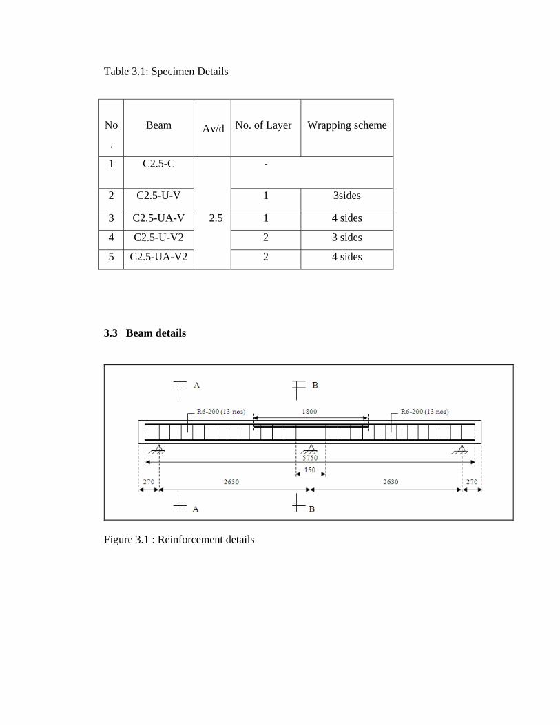
Table 3.1: Specimen Details
No
.
Beam
Av/d
No. of Layer
Wrapping scheme
1 C2.5-C -
2 C2.5-U-V 1 3sides
3 C2.5-UA-V 2.5 1 4 sides
4 C2.5-U-V2 2 3 sides
5 C2.5-UA-V2 2 4 sides
3.3 Beam details
Figure 3.1 : Reinforcement details
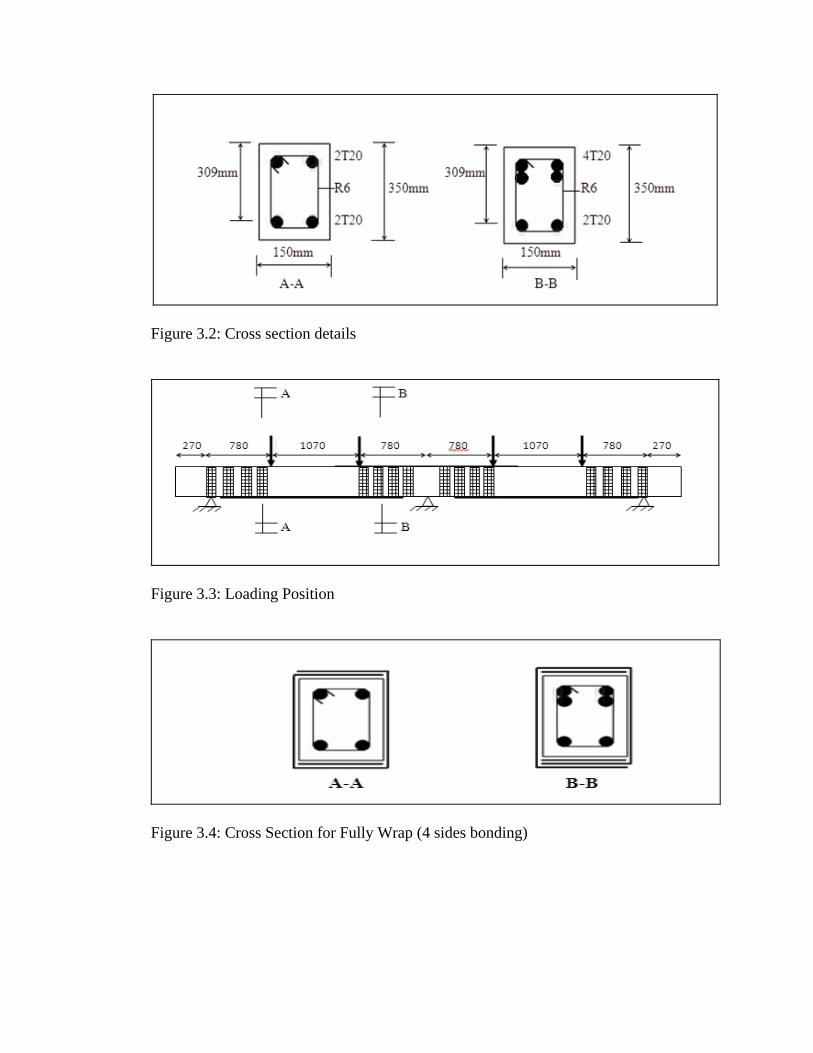
Figure 3.2: Cross section details
Figure 3.3: Loading Position
Figure 3.4: Cross Section for Fully Wrap (4 sides bonding)
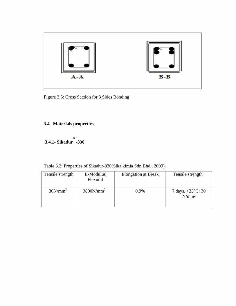
Figure 3.5: Cross Section for 3 Sides Bonding
3.4 Materials properties
3.4.1- Sikadur®
-330
Table 3.2: Properties of Sikadur-330(Sika kimia Sdn Bhd., 2009).
Tensile strength E-Modulus Flexural
Elongation at Break Tensile strength
30N/mm2 3800N/mm2 0.9% 7 days, +23°C: 30 N/mm²
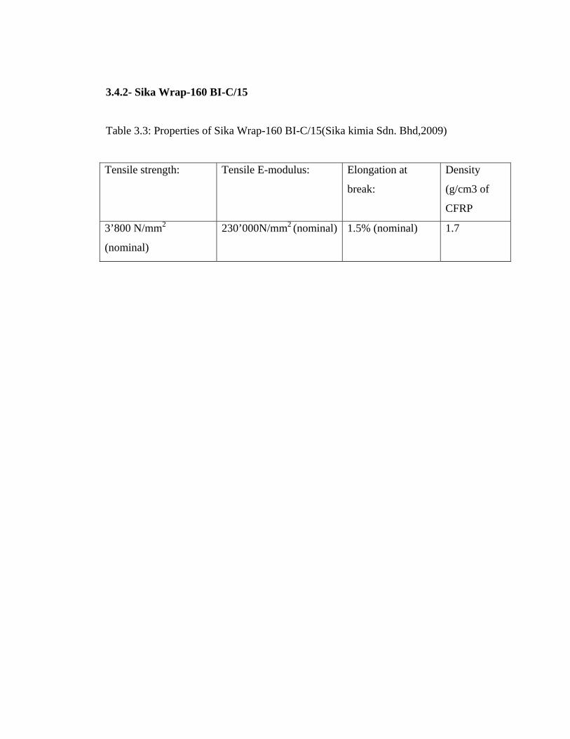
3.4.2- Sika Wrap-160 BI-C/15
Table 3.3: Properties of Sika Wrap-160 BI-C/15(Sika kimia Sdn. Bhd,2009)
Tensile strength: Tensile E-modulus: Elongation at
break:
Density
(g/cm3 of
CFRP
3’800 N/mm2
(nominal)
230’000N/mm2 (nominal) 1.5% (nominal) 1.7
References
ACI 440.2R, 2008, “Guide for the Design and Construction of Externally Bonded FRP
Systems for Strengthening of Concrete Structures,” American Concrete Institute
Chu kia (1998). “Reinforced concrete design”.
“Carlo Pellegrino (2009) . Flexural Strengthening of Reinforced Concrete Beams with
Prestressed FRP”.
“Feras alzzoubi a, Zhang and Zheng-liang 29 April (2007). Shear strengthening of
pre-damaged reinforced concrete beams with carbon fiber reinforced polymer sheet
strips”, Vol. 6 No. 4
Gamage, J.C.P.h,wong, M.B & Al mahidi R. (2005).”Performance of CFRP
strengthened concrete members under elevated temperatures”.
H. K. Lee† & S. K. Ha September 22 (2008). “Finite element analysis of shear-deficient
RC beams strengthened with CFRP strips/sheets”.Vol. 30, No. 2
Jayabrakash, (2006). “Shear strengthening of reinforced concrete beams using
externally bonded BI- directional carbon fiber reinforced polymer”.
Khalifa, A.M. (1999). “Shear performance of reinforced concrete beams strengthened
with advanced composites.University of Missouri-Rolla: ph.D.Thesis.
Liu Zihong,27 July 2007 ) “Testing and analysis of a fiber reinforced polymer”.
Manfredi Gaetano and Marisa Pecce 30 August (2006). “Durability issues of FRP rebars
in reinforced concrete members”.NO. 857–868
Mohamed (2009). “Finite Element Modeling o Reinforced Concrete Beams Strengthened
with FRP Laminates”. Vol.30 No.4 (2009), pp.526-541
Nabil F. Grace (May-June 2001).“Strengthening of negative moment region of
reinforced concrete beams using carbon fiber- reinforced polymer strips”. NO. 98-S33
Nadeem seddique (October 2009).“Experimental investigation of RC beams
strengthened with externally bonded FRP composites”.
Norris (1997). “Analysis of Retrofitted Reinforced Concrete Shear Beams using Carbon
Fiber Composites”.
Sikh kimia (2009). “Sikadar-330,2- part epoxy impregnation resin Malaysia”.
Vellore Gopalaratnam,( 2007). “Flexure shear response in fatigue of fiber reinforced
concrete beams with FRP tensile reinforcement. Local Centre” .pp 150-153.)
Wang (1995). “Shear Strengthening of Reinforced Concrete”.