an improved synchronous reference frame current control ...eprints.utm.my › id › eprint ›...
TRANSCRIPT

RESEARCH ARTICLE
An improved synchronous reference frame
current control strategy for a photovoltaic
grid-connected inverter under unbalanced
and nonlinear load conditions
Amirreza Naderipour1, Abdullah Asuhaimi Mohd Zin1*, Mohd Hafiz Bin Habibuddin1,
Mohammad Reza Miveh1, Josep M. Guerrero2
1 Faculty of Electrical Engineering, Universiti Teknologi Malaysia, UTM Skudai, Johor, Malaysia, 2 Institute
of Energy Technology, Aalborg University, Aalborg East, Denmark
Abstract
In recent years, renewable energy sources have been considered the most encouraging
resources for grid and off-grid power generation. This paper presents an improved current
control strategy for a three-phase photovoltaic grid-connected inverter (GCI) under unbal-
anced and nonlinear load conditions. It is challenging to suppress the harmonic content in
the output current below a pre-set value in the GCI. It is also difficult to compensate for
unbalanced loads even when the grid is under disruption due to total harmonic distortion
(THD) and unbalanced loads. The primary advantage and objective of this method is to
effectively compensate for the harmonic current content of the grid current and microgrid
without the use of any compensation devices, such as active and passive filters. This
method leads to a very low THD in both the GCI currents and the current exchanged with
the grid. The control approach is designed to control the active and reactive power and har-
monic current compensation, and it also corrects the system unbalance. The proposed con-
trol method features the synchronous reference frame (SRF) method. Simulation results are
presented to demonstrate the effective performance of the proposed method.
Introduction
Among the various renewable energy sources (RESs), photovoltaics (PVs) are the most prom-
ising environmental friendly and fastest growing clean and renewable energy source [1,2]. The
RESs are connected to the utility network or microgrid (MG) by an interface converter. An
MG is a local grid composed of distributed generators (DGs), energy storage systems and
loads and can operate in both grid-connected [3] and island modes [4]. Power quality prob-
lems are a specific concern with MGs because distortion harmonic sources can represent a
high proportion of the total loads or nonlinear loads (NLLs) in small-scale systems [5]. The
main limitation associated with MGs occurs when exchanging the current from the grid to the
MG [6–8]; this exchange is considered a source of harmonic distortion in a grid-connected
inverter (GCI) [9]. To improve the power quality in MGs, several approaches have been
PLOS ONE | DOI:10.1371/journal.pone.0164856 February 13, 2017 1 / 17
a1111111111
a1111111111
a1111111111
a1111111111
a1111111111
OPENACCESS
Citation: Naderipour A, Asuhaimi Mohd Zin A, Bin
Habibuddin MH, Miveh MR, Guerrero JM (2017)
An improved synchronous reference frame current
control strategy for a photovoltaic grid-connected
inverter under unbalanced and nonlinear load
conditions. PLoS ONE 12(2): e0164856.
doi:10.1371/journal.pone.0164856
Editor: Houbing Song, West Virginia University,
UNITED STATES
Received: May 27, 2016
Accepted: October 3, 2016
Published: February 13, 2017
Copyright: © 2017 Naderipour et al. This is an open
access article distributed under the terms of the
Creative Commons Attribution License, which
permits unrestricted use, distribution, and
reproduction in any medium, provided the original
author and source are credited.
Data Availability Statement: All relevant data are
within the manuscript.
Funding: The authors sincerely would like to
express their appreciation to the Universiti
Teknologi Malaysia (UTM) for supporting this work
through GUP Grant (Vote No: 15H65) and Ministry
of Higher Education (MOHE) for providing funds to
carry out the research reported in this paper.
Competing interests: The authors have declared
that no competing interests exist.
proposed [10]. Installing passive filters (PFs) in the appropriate locations, preferably close to
the harmonic generator, can lead to trapping of the harmonic currents near the source and
can reduce their distribution throughout the other parts of the system [11]. Active power filters
(APFs) have been proven as a flexible solution for compensating the harmonic distortion
caused by various NLLs in power distribution systems [12]. Hybrid compensation (HC) has
the advantages of both passive and active power filters for the improvement of power quality
problems [13]. Traditionally, the GCIs used in MGs connected to the main grid have behaved
as current sources [14]. The GCI controller should be able to correct an unbalanced system
and cancel the main harmonics to meet the waveform quality requirements of the local loads
and MGs [9]. The primary goal of a power-electronic interface inverter is to control the power
injection [15]. However, compensation for power quality problems, such as current harmon-
ics, can be achieved through appropriate control strategies. Consequently, the control of DGs
must be improved to meet the requirements when connected to the grid [16].
In the literature [9,17–24], several methods have been presented to control the DGs in
terms of a current harmonic compensator. The methods in [17] and [9] were proposed to
compensate for current harmonics in grid-connected MGs. The current controller proposed
in [17] uses the synchronous reference frame (SRF) and is composed of a proportional–inte-
gral (PI) controller and a repetitive controller (RC). The other study [9] proposed a cascaded
current and voltage control strategy for the interface converter in MGs. M. Hamzeh et al. [19]
proposed a control strategy that includes a harmonic impedance controller and a multi-pro-
portional resonant controller. Additionally, one researcher presented a control method for a
multi-bus MV MG under unbalanced and nonlinear load conditions [24]. Several controllers,
namely, PI controllers implemented in the dq frame as well (also constituting an SRF), a reso-
nant controller, a PI controller implemented in the abc frame, and a dead-beat (DB) predictive
controller, were proposed in [23]. In 2013 Savaghebi et al. published a paper in which they pro-
posed methods to compensate for the voltage unbalance at the RER terminal; the power quality
at the point of common coupling (PCC) is usually the main concern due to sensitive loads that
may be connected [25]. Mohamed Abbes et al. [26] proposed a control strategy for a three-
level, neutral point clamped (NPC) voltage source converter. Two current controllers were
designed to achieve grid current control.
Unfortunately, traditional APFs have several drawbacks, including higher cost, larger size,
higher power switch count, and complex control algorithms and interface circuits to compen-
sate for unbalanced and nonlinear loads.
Due to the aforementioned issues, this study presents a new inverter control method for
harmonic compensation. The proposed control strategy consists of an SRF method, which is
proposed to control power injection to the grid, provide harmonic current compensation and
correct the unbalanced system. The focus of the present paper is the reduction of total har-
monic distortion (THD) in the current flowing between the PCC and MG. Furthermore, simu-
lation studies are presented, discussed and analysed. The main proposed control methods are
as follows:
• voltage and current controllers;
• active and reactive power controllers;
• harmonic current compensation;
• current unbalance compensation.
This paper is organized as follows. The proposed control scheme for the DG GCI is dis-
cussed in Section II. In this section, details of the entire control structure, including the active
ISRF for PVGCI under unbalanced load
PLOS ONE | DOI:10.1371/journal.pone.0164856 February 13, 2017 2 / 17
and reactive power control unit and harmonic current compensation unit, are explained. Sim-
ulation results with three case studies are presented in Section III. Finally, conclusions are pre-
sented in Section IV.
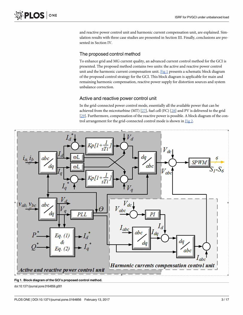
The proposed control method
To enhance grid and MG current quality, an advanced current control method for the GCI is
presented. The proposed method contains two units: the active and reactive power control
unit and the harmonic current compensation unit. Fig 1 presents a schematic block diagram
of the proposed control strategy for the GCI. This block diagram is applicable for main and
remaining harmonic compensation, reactive power supply for distortion sources and system
unbalance correction.
Active and reactive power control unit
In the grid-connected power control mode, essentially all the available power that can be
achieved from the microturbine (MT) [27], fuel cell (FC) [28] and PV is delivered to the grid
[29]. Furthermore, compensation of the reactive power is possible. A block diagram of the con-
trol arrangement for the grid-connected control mode is shown in Fig 2.
Fig 1. Block diagram of the GCI’s proposed control method.
doi:10.1371/journal.pone.0164856.g001
ISRF for PVGCI under unbalanced load
PLOS ONE | DOI:10.1371/journal.pone.0164856 February 13, 2017 3 / 17
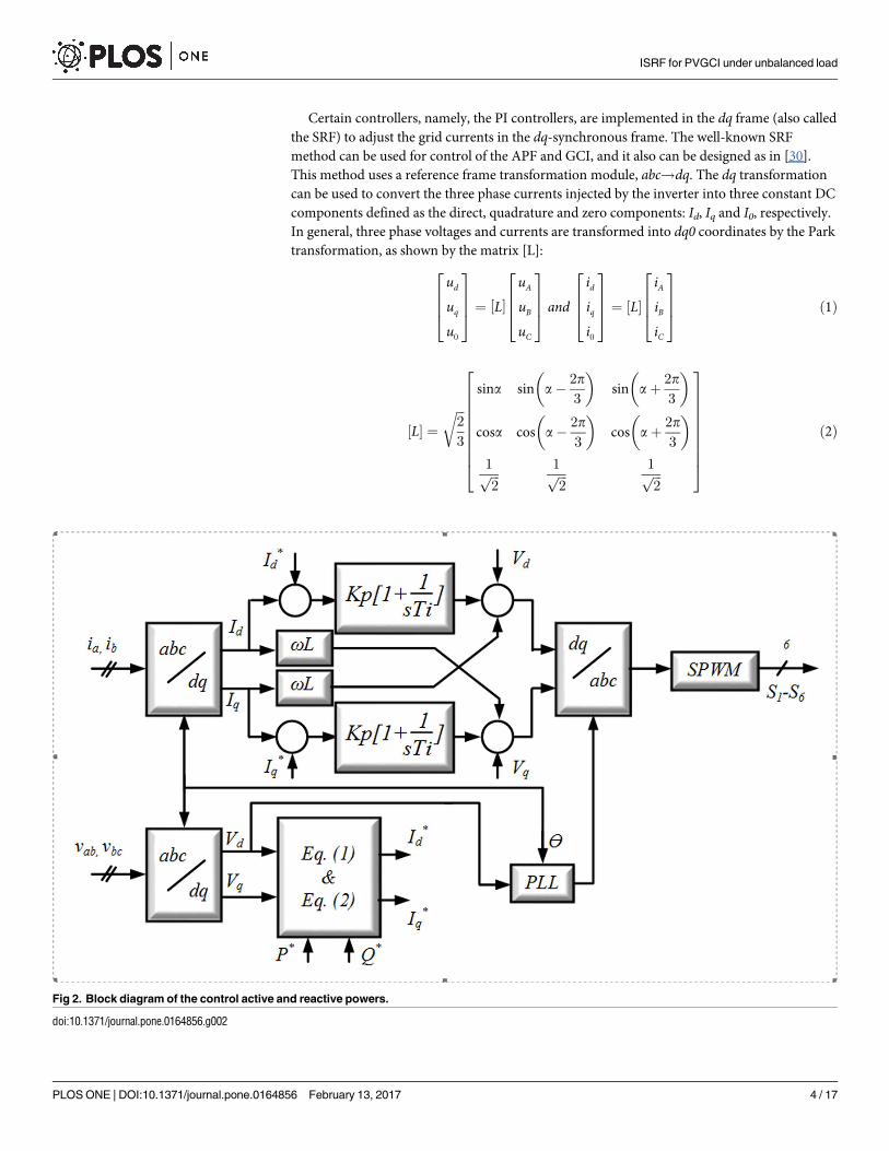
Certain controllers, namely, the PI controllers, are implemented in the dq frame (also called
the SRF) to adjust the grid currents in the dq-synchronous frame. The well-known SRF
method can be used for control of the APF and GCI, and it also can be designed as in [30].
This method uses a reference frame transformation module, abc!dq. The dq transformation
can be used to convert the three phase currents injected by the inverter into three constant DC
components defined as the direct, quadrature and zero components: Id, Iq and I0, respectively.
In general, three phase voltages and currents are transformed into dq0 coordinates by the Park
transformation, as shown by the matrix [L]:
ud
uq
u0
2
664
3
775 ¼ L½
uA
uB
uC
2
664
3
775 and
idiqi0
2
664
3
775 ¼ ½L
iAiBiC
2
664
3
775 ð1Þ
½L ¼ffiffiffi2
3
r
sina sin a 2p
3
sin aþ2p
3
cosa cos a 2p
3
cos aþ2p
3
1ffiffiffi2p
1ffiffiffi2p
1ffiffiffi2p
2
666666664
3
777777775
ð2Þ
Fig 2. Block diagram of the control active and reactive powers.
doi:10.1371/journal.pone.0164856.g002
ISRF for PVGCI under unbalanced load
PLOS ONE | DOI:10.1371/journal.pone.0164856 February 13, 2017 4 / 17
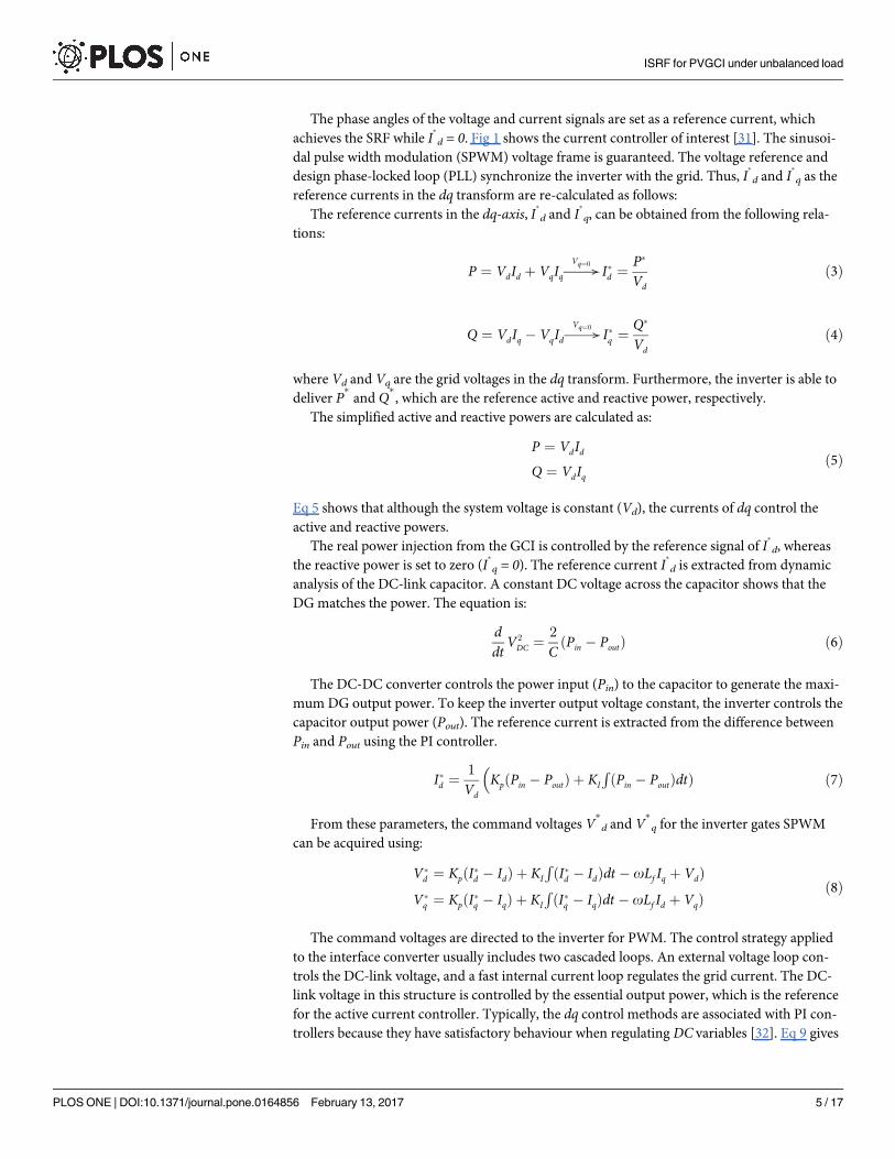
The phase angles of the voltage and current signals are set as a reference current, which
achieves the SRF while I
d = 0. Fig 1 shows the current controller of interest [31]. The sinusoi-
dal pulse width modulation (SPWM) voltage frame is guaranteed. The voltage reference and
design phase-locked loop (PLL) synchronize the inverter with the grid. Thus, I
d and I
q as the
reference currents in the dq transform are re-calculated as follows:
The reference currents in the dq-axis, I
d and I
q, can be obtained from the following rela-
tions:
P ¼ VdId þ VqIq!Vq¼0
Id ¼P
Vdð3Þ
Q ¼ VdIq VqId!Vq¼0
Iq ¼Q
Vdð4Þ
where Vd and Vq are the grid voltages in the dq transform. Furthermore, the inverter is able to
deliver P
and Q, which are the reference active and reactive power, respectively.
The simplified active and reactive powers are calculated as:
P ¼ VdIdQ ¼ VdIq
ð5Þ
Eq 5 shows that although the system voltage is constant (Vd), the currents of dq control the
active and reactive powers.
The real power injection from the GCI is controlled by the reference signal of I
d, whereas
the reactive power is set to zero (I
q = 0). The reference current I
d is extracted from dynamic
analysis of the DC-link capacitor. A constant DC voltage across the capacitor shows that the
DG matches the power. The equation is:
ddt
V2
DC ¼2
CPin Poutð Þ ð6Þ
The DC-DC converter controls the power input (Pin) to the capacitor to generate the maxi-
mum DG output power. To keep the inverter output voltage constant, the inverter controls the
capacitor output power (Pout). The reference current is extracted from the difference between
Pin and Pout using the PI controller.
Id ¼1
VdKp Pin Poutð Þ þ KI
RðPin PoutÞdtÞ ð7Þ
From these parameters, the command voltages V
d and V
q for the inverter gates SPWM
can be acquired using:
Vd ¼ KpðId IdÞ þ KI
RðId IdÞdt oLf Iq þ VdÞ
Vq ¼ KpðIq IqÞ þ KI
RðIq IqÞdt oLf Id þ VqÞ
ð8Þ
The command voltages are directed to the inverter for PWM. The control strategy applied
to the interface converter usually includes two cascaded loops. An external voltage loop con-
trols the DC-link voltage, and a fast internal current loop regulates the grid current. The DC-
link voltage in this structure is controlled by the essential output power, which is the reference
for the active current controller. Typically, the dq control methods are associated with PI con-
trollers because they have satisfactory behaviour when regulating DC variables [32]. Eq 9 gives
ISRF for PVGCI under unbalanced load
PLOS ONE | DOI:10.1371/journal.pone.0164856 February 13, 2017 5 / 17
the matrix transfer function in dq coordinates:
GðdqÞPI sð Þ ¼Kp þ
Ki
s0
0 Kp þKi
s
2
664
3
775 ð9Þ
where Kp and Ki are the proportional and integral gain of the controller, respectively.
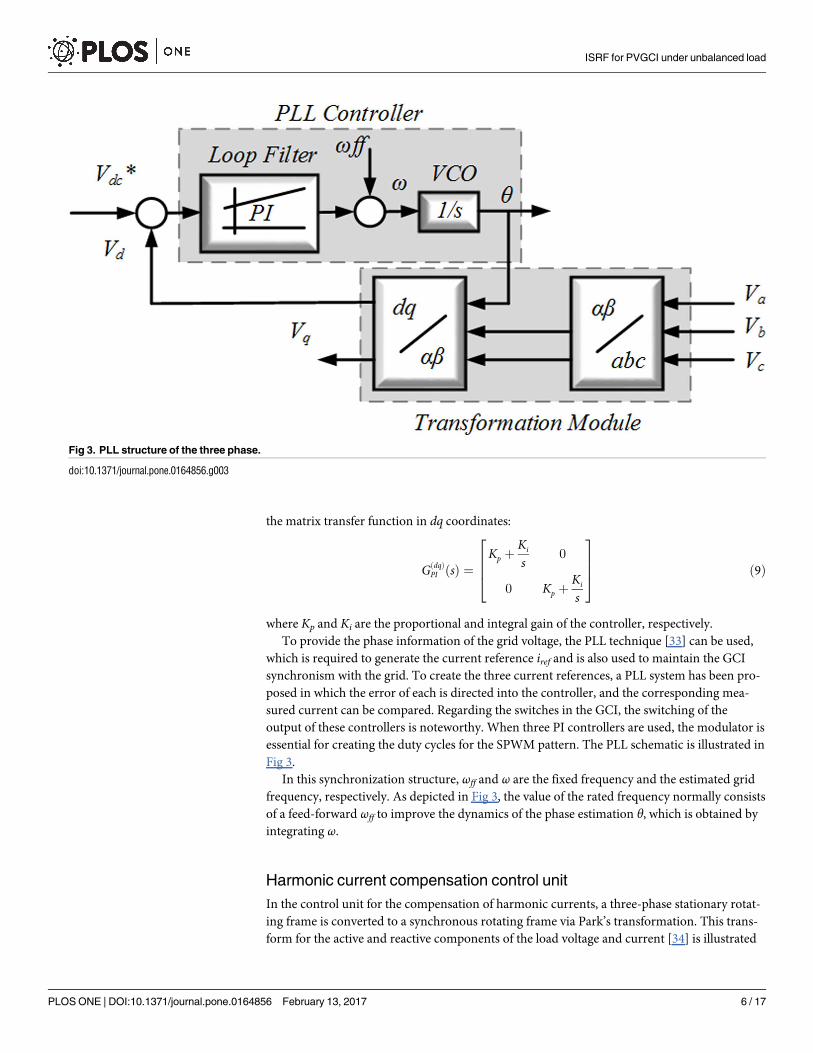
To provide the phase information of the grid voltage, the PLL technique [33] can be used,
which is required to generate the current reference iref and is also used to maintain the GCI
synchronism with the grid. To create the three current references, a PLL system has been pro-
posed in which the error of each is directed into the controller, and the corresponding mea-
sured current can be compared. Regarding the switches in the GCI, the switching of the
output of these controllers is noteworthy. When three PI controllers are used, the modulator is
essential for creating the duty cycles for the SPWM pattern. The PLL schematic is illustrated in
Fig 3.
In this synchronization structure, ωff and ω are the fixed frequency and the estimated grid
frequency, respectively. As depicted in Fig 3, the value of the rated frequency normally consists
of a feed-forward ωff to improve the dynamics of the phase estimation θ, which is obtained by
integrating ω.
Harmonic current compensation control unit
In the control unit for the compensation of harmonic currents, a three-phase stationary rotat-
ing frame is converted to a synchronous rotating frame via Park’s transformation. This trans-
form for the active and reactive components of the load voltage and current [34] is illustrated
Fig 3. PLL structure of the three phase.
doi:10.1371/journal.pone.0164856.g003
ISRF for PVGCI under unbalanced load
PLOS ONE | DOI:10.1371/journal.pone.0164856 February 13, 2017 6 / 17
in (10):
idiq
" #
¼
siny sin y 2p
3
sin yþ2p
3
cosy cos y 2p
3
cos yþ2p
3
2
6664
3
7775
ð10Þ
id ¼ Idþ ~I
dð11Þ
iq ¼ Iqþ ~I
qð12Þ
The active and reactive components of the current are decomposed into the dq components
in (11) and (12).
The current source generates the fundamental component of the d-axis of the load and the
filter DC component associated with the strategy of harmonic compensation.
The steady-state error of the inverter’s DC component is eliminated by the PI controller to
keep the voltage across the capacitor constant. The error voltage is computed by comparing
the DC capacitor voltage with the reference voltage. Moreover, to regulate the capacitor under
dynamic conditions and mitigate the steady-state error, the output of the PI controller is modi-
fied. The PLL performance has a significant effect on the dq transform of the output signal. In
a PLL, the rotating reference frame (ωt) is set as a fundamental component. Application of the
inverse of Park’s transformation is represented in (13) through (15). The dq rotating frame is
converted back to a three-phase stationery frame:
isa ¼ idsinðotÞ þ cosðotÞ ð13Þ
isb ¼ idsin ot 2p
3
þ cos ot 2p
3
ð14Þ
isc ¼ idsin ot þ2p
3
þ cos ot þ2p
3
ð15Þ
This theory is only applicable to the three-phase system. Because the harmonic current
compensation controller addresses DC quantities, its control unit is entirely stable. However,
there is a time delay in filtering the DC quantities due to the instantaneous computation of
quantities [35]. The extracted reference signal is then used to trigger the gate driver controller,
which will allow the inverter to introduce the desired compensation current into the system.
Simulation results
In a basic MG architecture (Fig 4), the system is assumed to be radial with several feeders and
a collection of NLLs. To demonstrate the effectiveness of the proposed control strategy, the
system in Fig 4 was simulated in MATLAB/Simulink.
This MG includes three DGs, namely, the PV, MT and FC, which are connected to the grid
by the power electronic interface. The proposed control methods are applied to the PV; how-
ever, the FC is connected to the grid by the ordinary interface converter without the control
strategy. The MT has a frequency of 1,500 Hz, which is similar to a normal generator, but its
output voltage has a frequency of 1,500 Hz. Therefore, the effective voltage of the output phase
of this 220 V MT has a frequency of 1,500 Hz, but this source cannot be connected to a power
system with a frequency of 50 Hz. For this purpose, the input voltage must first be rectified
ISRF for PVGCI under unbalanced load
PLOS ONE | DOI:10.1371/journal.pone.0164856 February 13, 2017 7 / 17
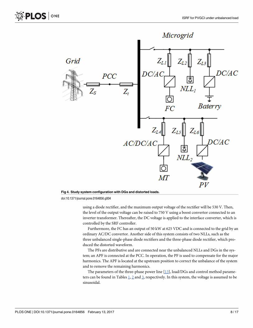
using a diode rectifier, and the maximum output voltage of the rectifier will be 530 V. Then,
the level of the output voltage can be raised to 750 V using a boost convertor connected to an
inverter transformer. Thereafter, the DC voltage is applied to the interface converter, which is
controlled by the SRF controller.
Furthermore, the FC has an output of 50 kW at 625 VDC and is connected to the grid by an
ordinary AC/DC convertor. Another side of this system consists of two NLLs, such as the
three unbalanced single-phase diode rectifiers and the three-phase diode rectifier, which pro-
duced the distorted waveform.
The PFs are distributive and are connected near the unbalanced NLLs and DGs in the sys-
tem; an APF is connected at the PCC. In operation, the PF is used to compensate for the major
harmonics. The APF is located at the upstream position to correct the unbalance of the system
and to remove the remaining harmonics.
The parameters of the three-phase power line [13], load/DGs and control method parame-
ters can be found in Tables 1, 2 and 3, respectively. In this system, the voltage is assumed to be
sinusoidal.
Fig 4. Study system configuration with DGs and distorted loads.
doi:10.1371/journal.pone.0164856.g004
ISRF for PVGCI under unbalanced load
PLOS ONE | DOI:10.1371/journal.pone.0164856 February 13, 2017 8 / 17
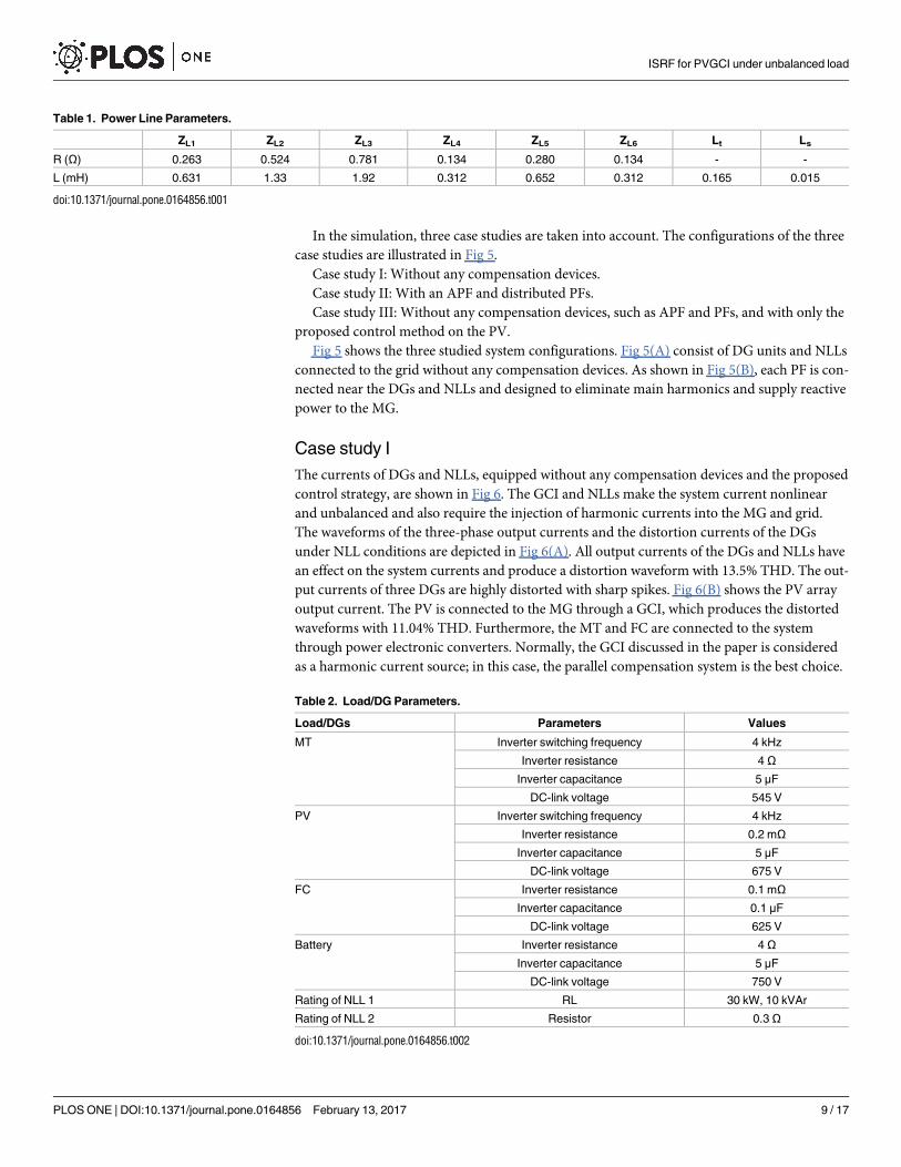
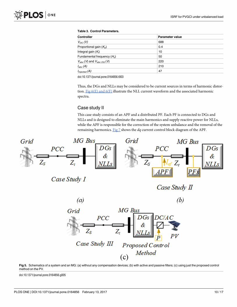
In the simulation, three case studies are taken into account. The configurations of the three
case studies are illustrated in Fig 5.
Case study I: Without any compensation devices.
Case study II: With an APF and distributed PFs.
Case study III: Without any compensation devices, such as APF and PFs, and with only the
proposed control method on the PV.
Fig 5 shows the three studied system configurations. Fig 5(A) consist of DG units and NLLs
connected to the grid without any compensation devices. As shown in Fig 5(B), each PF is con-
nected near the DGs and NLLs and designed to eliminate main harmonics and supply reactive
power to the MG.
Case study I
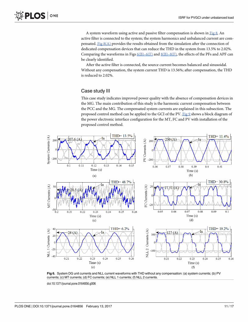
The currents of DGs and NLLs, equipped without any compensation devices and the proposed
control strategy, are shown in Fig 6. The GCI and NLLs make the system current nonlinear
and unbalanced and also require the injection of harmonic currents into the MG and grid.
The waveforms of the three-phase output currents and the distortion currents of the DGs
under NLL conditions are depicted in Fig 6(A). All output currents of the DGs and NLLs have
an effect on the system currents and produce a distortion waveform with 13.5% THD. The out-
put currents of three DGs are highly distorted with sharp spikes. Fig 6(B) shows the PV array
output current. The PV is connected to the MG through a GCI, which produces the distorted
waveforms with 11.04% THD. Furthermore, the MT and FC are connected to the system
through power electronic converters. Normally, the GCI discussed in the paper is considered
as a harmonic current source; in this case, the parallel compensation system is the best choice.
Table 1. Power Line Parameters.
ZL1 ZL2 ZL3 ZL4 ZL5 ZL6 Lt Ls
R (Ω) 0.263 0.524 0.781 0.134 0.280 0.134 - -
L (mH) 0.631 1.33 1.92 0.312 0.652 0.312 0.165 0.015
doi:10.1371/journal.pone.0164856.t001
Table 2. Load/DG Parameters.
Load/DGs Parameters Values
MT Inverter switching frequency 4 kHz
Inverter resistance 4 ΩInverter capacitance 5 μF
DC-link voltage 545 V
PV Inverter switching frequency 4 kHz
Inverter resistance 0.2 mΩInverter capacitance 5 μF
DC-link voltage 675 V
FC Inverter resistance 0.1 mΩInverter capacitance 0.1 μF
DC-link voltage 625 V
Battery Inverter resistance 4 ΩInverter capacitance 5 μF
DC-link voltage 750 V
Rating of NLL 1 RL 30 kW, 10 kVAr
Rating of NLL 2 Resistor 0.3 Ω
doi:10.1371/journal.pone.0164856.t002
ISRF for PVGCI under unbalanced load
PLOS ONE | DOI:10.1371/journal.pone.0164856 February 13, 2017 9 / 17
Thus, the DGs and NLLs may be considered to be current sources in terms of harmonic distor-
tion. Fig 6(E) and 6(F) illustrate the NLL current waveform and the associated harmonic
spectra.
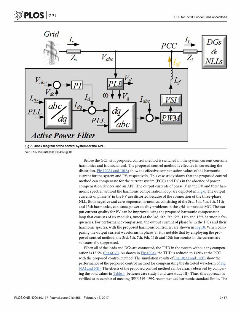
Case study II
This case study consists of an APF and a distributed PF. Each PF is connected to DGs and
NLLs and is designed to eliminate the main harmonics and supply reactive power for NLLs,
while the APF is responsible for the correction of the system unbalance and the removal of the
remaining harmonics. Fig 7 shows the dq current control block diagram of the APF.
Table 3. Control Parameters.
Controller Parameter value
VDC (V) 688
Proportional gain (Kp) 0.4
Integral gain (Ki) 10
Fundamental frequency (Hz) 50
Vabc (V) and Vabc DG (V) 220
Iabc (A) 210
Iinjected (A) 47
doi:10.1371/journal.pone.0164856.t003
Fig 5. Schematics of a system and an MG: (a) without any compensation devices; (b) with active and passive filters; (c) using just the proposed control
method on the PV.
doi:10.1371/journal.pone.0164856.g005
ISRF for PVGCI under unbalanced load
PLOS ONE | DOI:10.1371/journal.pone.0164856 February 13, 2017 10 / 17
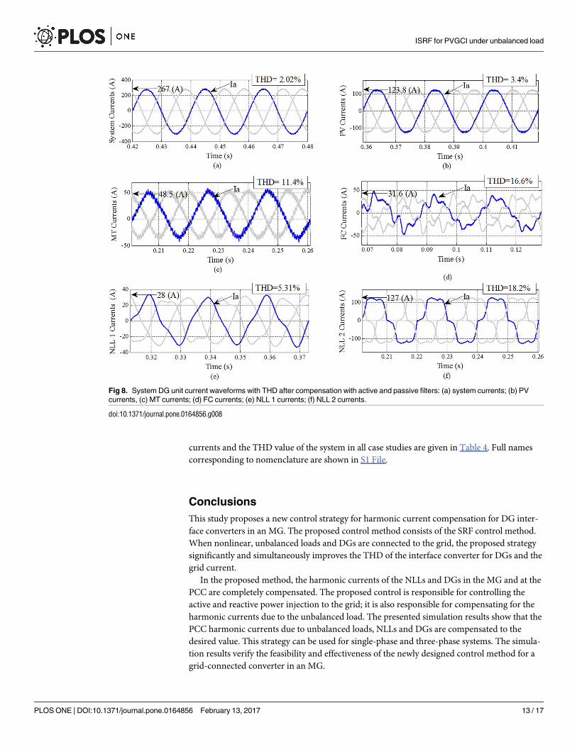
A system waveform using active and passive filter compensation is shown in Fig 8. An
active filter is connected to the system; the system harmonics and unbalanced current are com-
pensated. Fig 8(A) provides the results obtained from the simulation after the connection of
dedicated compensation devices that can reduce the THD in the system from 13.5% to 2.02%.
Comparing the waveforms in Figs 6(B)–6(F) and 8(B)–8(F), the effects of the PFs and APF can
be clearly identified.
After the active filter is connected, the source current becomes balanced and sinusoidal.
Without any compensation, the system current THD is 13.56%; after compensation, the THD
is reduced to 2.02%.
Case study III
This case study indicates improved power quality with the absence of compensation devices in
the MG. The main contribution of this study is the harmonic current compensation between
the PCC and the MG. The compensated system currents are explained in this subsection. The
proposed control method can be applied to the GCI of the PV. Fig 9 shows a block diagram of
the power electronic interface configuration for the MT, FC and PV with installation of the
proposed control method.
Fig 6. System DG unit currents and NLL current waveforms with THD without any compensation: (a) system currents; (b) PV
currents; (c) MT currents; (d) FC currents; (e) NLL 1 currents; (f) NLL 2 currents.
doi:10.1371/journal.pone.0164856.g006
ISRF for PVGCI under unbalanced load
PLOS ONE | DOI:10.1371/journal.pone.0164856 February 13, 2017 11 / 17
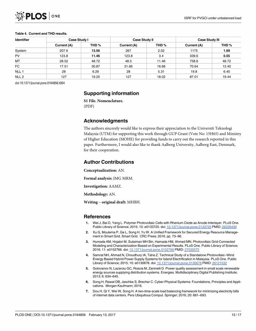
Before the GCI with proposed control method is switched in, the system current contains
harmonics and is unbalanced. The proposed control method is effective in correcting the
distortion. Fig 10(A) and 10(B) show the effective compensation values of the harmonic
current for the system and PV, respectively. This case study shows that the proposed control
method can compensate for the current system (PCC) and DGs in the absence of power
compensation devices and an APF. The output currents of phase ‘a’ in the PV and their har-
monic spectra, without the harmonic compensation loop, are depicted in Fig 6. The output
currents of phase ‘a’ in the PV are distorted because of the connection of the three-phase
NLL. Both negative and zero sequence harmonics, consisting of the 3rd, 5th, 7th, 9th, 11th
and 13th harmonics, can cause power quality problems in the grid-connected MG. The out-
put current quality for PV can be improved using the proposed harmonic compensator
loop that consists of six modules, tuned at the 3rd, 5th, 7th, 9th, 11th and 13th harmonic fre-
quencies. For performance comparison, the output current of phase ‘a’ in the DGs and their
harmonic spectra, with the proposed harmonic controller, are shown in Fig 10. When com-
paring the output current waveforms in phase ‘a’, it is notable that by employing the pro-
posed control method, the 3rd, 5th, 7th, 9th, 11th and 13th harmonics in the current are
substantially suppressed.
When all of the loads and DGs are connected, the THD in the system without any compen-
sation is 13.5% (Fig 6(A)). As shown in Fig 10(A), the THD is reduced to 1.69% at the PCC
with the proposed control method. The simulation results of Fig 10(A) and 10(B) show the
performance of the proposed control method for compensating the distorted waveform of Fig
6(A) and 6(B). The effects of the proposed control method can be clearly observed by compar-
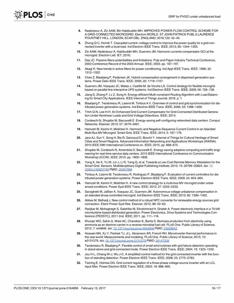
ing the bold values in Table 4 (between case study I and case study III). Thus, this approach is
verified to be capable of meeting IEEE 519–1992 recommended harmonic standard limits. The
Fig 7. Block diagram of the control system for the APF.
doi:10.1371/journal.pone.0164856.g007
ISRF for PVGCI under unbalanced load
PLOS ONE | DOI:10.1371/journal.pone.0164856 February 13, 2017 12 / 17
currents and the THD value of the system in all case studies are given in Table 4. Full names
corresponding to nomenclature are shown in S1 File.
Conclusions
This study proposes a new control strategy for harmonic current compensation for DG inter-
face converters in an MG. The proposed control method consists of the SRF control method.
When nonlinear, unbalanced loads and DGs are connected to the grid, the proposed strategy
significantly and simultaneously improves the THD of the interface converter for DGs and the
grid current.
In the proposed method, the harmonic currents of the NLLs and DGs in the MG and at the
PCC are completely compensated. The proposed control is responsible for controlling the
active and reactive power injection to the grid; it is also responsible for compensating for the
harmonic currents due to the unbalanced load. The presented simulation results show that the
PCC harmonic currents due to unbalanced loads, NLLs and DGs are compensated to the
desired value. This strategy can be used for single-phase and three-phase systems. The simula-
tion results verify the feasibility and effectiveness of the newly designed control method for a
grid-connected converter in an MG.
Fig 8. System DG unit current waveforms with THD after compensation with active and passive filters: (a) system currents; (b) PV
currents, (c) MT currents; (d) FC currents; (e) NLL 1 currents; (f) NLL 2 currents.
doi:10.1371/journal.pone.0164856.g008
ISRF for PVGCI under unbalanced load
PLOS ONE | DOI:10.1371/journal.pone.0164856 February 13, 2017 13 / 17
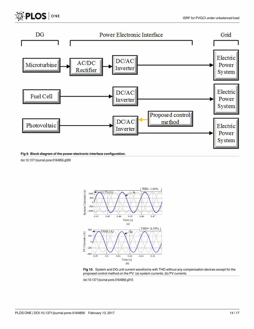
Fig 9. Block diagram of the power electronic interface configuration.
doi:10.1371/journal.pone.0164856.g009
Fig 10. System and DG unit current waveforms with THD without any compensation devices except for the
proposed control method on the PV: (a) system currents; (b) PV currents.
doi:10.1371/journal.pone.0164856.g010
ISRF for PVGCI under unbalanced load
PLOS ONE | DOI:10.1371/journal.pone.0164856 February 13, 2017 14 / 17
Supporting information
S1 File. Nomenclature.
(PDF)
Acknowledgments
The authors sincerely would like to express their appreciation to the Universiti Teknologi
Malaysia (UTM) for supporting this work through GUP Grant (Vote No: 15H65) and Ministry
of Higher Education (MOHE) for providing funds to carry out the research reported in this
paper. Furthermore, I would also like to thank Aalborg University, Aalborg East, Denmark,
for their cooperation.
Author Contributions
Conceptualization: AN.
Formal analysis: JMG MRM.
Investigation: AAMZ.
Methodology: AN.
Writing – original draft: MHBH.
References1. Wei J, Bai D, Yang L. Polymer Photovoltaic Cells with Rhenium Oxide as Anode Interlayer. PLoS One.
Public Library of Science; 2015; 10: e0133725. doi: 10.1371/journal.pone.0133725 PMID: 26226439
2. Xu G, Moulema P, Ge L, Song H, Yu W. A Unified Framework for Secured Energy Resource Manage-
ment in Smart Grid. Smart Grid. CRC Press; 2016. pp. 73–96.
3. Humada AM, Hojabri M, Sulaiman MH Bin, Hamada HM, Ahmed MN. Photovoltaic Grid-Connected
Modeling and Characterization Based on Experimental Results. PLoS One. Public Library of Science;
2016; 11: e0152766. doi: 10.1371/journal.pone.0152766 PMID: 27035575
4. Samrat NH, Ahmad N, Choudhury IA, Taha Z. Technical Study of a Standalone Photovoltaic–Wind
Energy Based Hybrid Power Supply Systems for Island Electrification in Malaysia. PLoS One. Public
Library of Science; 2015; 10: e0130678. doi: 10.1371/journal.pone.0130678 PMID: 26121032
5. Golovanov N, Lazaroiu GC, Roscia M, Zaninelli D. Power quality assessment in small scale renewable
energy sources supplying distribution systems. Energies. Multidisciplinary Digital Publishing Institute;
2013; 6: 634–645.
6. Song H, Rawat DB, Jeschke S, Brecher C. Cyber-Physical Systems: Foundations, Principles and Appli-
cations. Morgan Kaufmann; 2016.
7. Dou H, Qi Y, Wei W, Song H. A two-time-scale load balancing framework for minimizing electricity bills
of internet data centers. Pers Ubiquitous Comput. Springer; 2016; 20: 681–693.
Table 4. Current and THD results.
Identifier Case Study I Case Study II Case Study III
Current (A) THD % Current (A) THD % Current (A) THD %
System 207.6 13.56 267 2.02 1175 1.69
PV 123.8 11.46 123.8 3.4 339.6 0.55
MT 28.52 48.72 48.5 11.46 758.6 48.72
FC 17.51 30.87 31.66 16.68 70.64 12.40
NLL 1 28 6.26 28 5.31 19.8 6.40
NLL 2 127 19.25 127 18.02 87.01 19.44
doi:10.1371/journal.pone.0164856.t004
ISRF for PVGCI under unbalanced load
PLOS ONE | DOI:10.1371/journal.pone.0164856 February 13, 2017 15 / 17
8. Naderipour A, Zin AAM, Bin Habibuddin MH. IMPROVED POWER-FLOW CONTROL SCHEME FOR
A GRID-CONNECTED MICROGRID. Electron WORLD. ST JOHN PATRICK PUBL 6 LAURENCE
POUNTNEY HILL, LONDON, EC4R OBL, ENGLAND; 2016;122: 42–45.
9. Zhong Q-C, Hornik T. Cascaded current–voltage control to improve the power quality for a grid-con-
nected inverter with a local load. Ind Electron IEEE Trans. IEEE; 2013; 60: 1344–1355.
10. Zin AAM, Naderipour A, Habibuddin MH, Guerrero JM. Harmonic currents compensator GCI at the
microgrid. Electron Lett. IET; 2016;
11. Das JC. Passive filters-potentialities and limitations. Pulp and Paper Industry Technical Conference,
2003 Conference Record of the 2003 Annual. IEEE; 2003. pp. 187–197.
12. Akagi H. New trends in active filters for power conditioning. Ind Appl IEEE Trans. IEEE; 1996; 32:
1312–1322.
13. Chen Z, Blaabjerg F, Pedersen JK. Hybrid compensation arrangement in dispersed generation sys-
tems. Power Deliv IEEE Trans. IEEE; 2005; 20: 1719–1727.
14. Guerrero JM, Vasquez JC, Matas J, Castilla M, de Vicuña LG. Control strategy for flexible microgrid
based on parallel line-interactive UPS systems. Ind Electron IEEE Trans. IEEE; 2009; 56: 726–736.
15. Jiang D, Zhang P, Lv Z, Song H. Energy-efficient Multi-constraint Routing Algorithm with Load Balanc-
ing for Smart City Applications. IEEE Internet of Things Journal. 2016. p. 1.
16. Blaabjerg F, Teodorescu R, Liserre M, Timbus A V. Overview of control and grid synchronization for dis-
tributed power generation systems. Ind Electron IEEE Trans. IEEE; 2006; 53: 1398–1409.
17. Trinh Q-N, Lee H-H. An Enhanced Grid Current Compensator for Grid-Connected Distributed Genera-
tion Under Nonlinear Loads and Grid Voltage Distortions. IEEE; 2014;
18. Cordeschi N, Shojafar M, Baccarelli E. Energy-saving self-configuring networked data centers. Comput
Networks. Elsevier; 2013; 57: 3479–3491.
19. Hamzeh M, Karimi H, Mokhtari H. Harmonic and Negative-Sequence Current Control in an Islanded
Multi-Bus MV Microgrid. Smart Grid, IEEE Trans. IEEE; 2014; 5: 167–176.
20. Jara AJ, Sun Y, Song H, Bie R, Genooud D, Bocchi Y. Internet of Things for Cultural Heritage of Smart
Cities and Smart Regions. Advanced Information Networking and Applications Workshops (WAINA),
2015 IEEE 29th International Conference on. IEEE; 2015. pp. 668–675.
21. Shojafar M, Cordeschi N, Amendola D, Baccarelli E. Energy-saving adaptive computing and traffic engi-
neering for real-time-service data centers. 2015 IEEE International Conference on Communication
Workshop (ICCW). IEEE; 2015. pp. 1800–1806.
22. Yang X, He X, Yu W, Lin J, Li R, Yang Q, et al. Towards a Low-Cost Remote Memory Attestation for the
Smart Grid. Sensors. Multidisciplinary Digital Publishing Institute; 2015; 15: 20799–20824. doi: 10.
3390/s150820799 PMID: 26307998
23. Timbus A, Liserre M, Teodorescu R, Rodriguez P, Blaabjerg F. Evaluation of current controllers for dis-
tributed power generation systems. Power Electron IEEE Trans. IEEE; 2009; 24: 654–664.
24. Hamzeh M, Karimi H, Mokhtari H. A new control strategy for a multi-bus MV microgrid under unbal-
anced conditions. Power Syst IEEE Trans. IEEE; 2012; 27: 2225–2232.
25. Savaghebi M, Jalilian A, Vasquez JC, Guerrero JM. Autonomous voltage unbalance compensation in
an islanded droop-controlled microgrid. Ind Electron IEEE Trans. IEEE; 2013; 60: 1390–1402.
26. Abbes M, Belhadj J. New control method of a robust NPC converter for renewable energy sources grid
connection. Electr Power Syst Res. Elsevier; 2012; 88: 52–63.
27. Ranjbar M, Mohaghegh S, Salehifar M, Ebrahimirad H, Ghaleh A. Power electronic interface in a 70 kW
microturbine-based distributed generation. Power Electronics, Drive Systems and Technologies Con-
ference (PEDSTC), 2011 2nd. IEEE; 2011. pp. 111–116.
28. Khunjar WO, Sahin A, West AC, Chandran K, Banta S. Biomass production from electricity using
ammonia as an electron carrier in a reverse microbial fuel cell. PLoS One. Public Library of Science;
2012; 7: e44846. doi: 10.1371/journal.pone.0044846 PMID: 23028643
29. Hossain MA, Xu Y, Peshek TJ, Ji L, Abramson AR, French RH. Microinverter thermal performance in
the real-world: Measurements and modeling. PLoS One. Public Library of Science; 2015; 10:
e0131279. doi: 10.1371/journal.pone.0131279 PMID: 26147339
30. Teodorescu R, Blaabjerg F. Flexible control of small wind turbines with grid failure detection operating
in stand-alone and grid-connected mode. Power Electron IEEE Trans. IEEE; 2004; 19: 1323–1332.
31. Jou H-L, Chiang W-J, Wu J-C. A simplified control method for the grid-connected inverter with the func-
tion of islanding detection. Power Electron IEEE Trans. IEEE; 2008; 23: 2775–2783.
32. Twining E, Holmes DG. Grid current regulation of a three-phase voltage source inverter with an LCL
input filter. Power Electron IEEE Trans. IEEE; 2003; 18: 888–895.
ISRF for PVGCI under unbalanced load
PLOS ONE | DOI:10.1371/journal.pone.0164856 February 13, 2017 16 / 17

33. Arruda LN, Silva SM. PLL structures for utility connected systems. Industry Applications Conference,
2001 Thirty-Sixth IAS Annual Meeting Conference Record of the 2001 IEEE. IEEE; 2001. pp. 2655–
2660.
34. Salam Z, Tan PC, Jusoh A. Harmonics mitigation using active power filter: A technological review. Elek-
trika. Faculty of Electrical Engineering; 2006; 8: 17–26.
35. Shi P, Zhang Y, Chadli M, Agarwal RK. Mixed H-Infinity and Passive Filtering for Discrete Fuzzy Neural
Networks With Stochastic Jumps and Time Delays. IEEE; 2015;
ISRF for PVGCI under unbalanced load
PLOS ONE | DOI:10.1371/journal.pone.0164856 February 13, 2017 17 / 17