wan nur azhani bt w.samsudin
TRANSCRIPT
AC MOTOR POSITION CONTROL USING FUZZY LOGIC CONTROLLER
WAN NUR AZHANI BT W.SAMSUDIN
This thesis is submitted as partial fulfillment of the requirements for the award of the
Bachelor Degree of Electrical Engineering (Electronics)
Faculty of Electrical & Electronics Engineering
University Malaysia Pahang
APRIL 2007
ABSTRACT
Motor position control is very important in rotating machinery applications.
There are many applications that have been developed based on motor position
control theory, such as crane controller, lift and conveyor. The position control of an
ac motor is very difficult to be implemented by using traditional control techniques,
as it requires a very complex mathematical model. The purpose for this project is to
describe the research on fuzzy logic controller (FLC) design based on programmable
logic controller (PLC) in order to control the position of an ac motor of University
Malaysia Pahang (UMP) mini conveyor. By using FLC, the conveyor will stop at the
desired point set by the user with minimum error. The model of the PLC that has
been used in this project is OMRON CQMIH-CPU5I.Before the controller was
developed, numbers of simulations were done using MATLAB Fuzzy Logic Toolbox
and SIMTJLINK. There are three rules that have been implemented in this project,
which used three membership functions. Based on the simulation, it can be
concluded that the system which has many rules in the fuzzy logic controller
produced better response compared to the system using a few rules.
V
ABSTRAK
Sistem kawalan motor adalah sangat penting dalam aplikasi-aplikasi yang
menggunakan motor sebagai keperluan utama dalam sesuatu proses.Terdapat banyak
aplikasi yang telah dijalankan berdasarkan teori sistem kawalan motor.Antaranya
ialah system kawalan kren, hf dan konveyor.Dalam proses mengawal pergerakan
motor, kajian telah menunjukkan bahawa motor arus ulang alik adalah susah untuk
dikawal jika dibandingkan dengan motor arus terus. Dengan menggunakan teknik
kawalan tradisional, proses kawalan akan menjadi lebih sukar kerana Ia memerlukan
model matematik yang kompleks. Oleh sebab itu, pelbagai cara dan teknik telah
dijalankan untuk mengatasi masalah mi. Tujuan projek ml dijalankan adalah untuk
mengkaji salah satu antara hangkah untuk mengatasi masalah yang dinyatakan,iaitu
sistem kawalan logik dengan menggunakan PLC dan diaphikasikan dengan
menggunakan konveyor mini IJMP. Dengan menggunakan sistem kawalan logik,
konveyor akan berhenti pada tempat atau sudut yang telah ditentukan oleh pengguna
pada sedikit ralat. Model PLC yang telah digunakan dalam projek mi OMRON
CQM1H-CPU51. Sebelum sistem logik mi dibentuk, simulasi telab dilakukan
terlebih dahulu dengan meggunakan MATLAB Fuzzy Logic Toolbox dan MATLAB
Simuhink. Terdapat tiga arahan yang digunakan dalam projek ml. Ketiga-tiga arahan
mi menggunakan tiga fungsi hubungan. Berdasarkan simulasi yang telah dijalankan,
ianya membuktikan bahawa sistem kawalan logik yang menggunakan lebih banyak
arahan akan menghasilkan respons yang lebih baik dan lebih tepat berbanding
dengan sistem yang menggunakan bilangan arahan yang sedikit.
vi
TABLE OF CONTENTS
CHAPTER TITLE PAGE
TITLE PAGE
DECLARATION
DEDICATION
ACKNOWLEDGEMENT iv
ABSTRACT v
ABSTRAK iv
TABLE OF CONTENTS vii
LIST OF TABLES x
LIST OF FIGURES xi
VII
TABLE OF CONTENTS
CHAPTER TITLE PAGE
I INTRODUCTION I
1.1 Overview I
1.2 Objective 2
1.3 Scope 2
1.4 Problem Statement 2
1.5 Thesis Organization 3
2 LITERATURE REVIEW
2.1 Introduction 4
2.2 Fuzzy Inference System 6
2.2.1 Fuzzy Set Definition 7
2.2.2 Input Fuzzy Sets 7
2.23 Output Fuzzy Sets 8
2.2.4 Fuzzification 8
2.2.5 Rule Base 9
2.2.6 Fuzzy Operators 9
2.2.7 Implication 9
2.2.8 Aggregation 10
2.2.9 Defuzzification 10
2.3 PLC 11
2.4 Single Phase Ac Motor 12
vii'
ix
3 METHODOLOGY
3.1 Introduction 13
3.2 Methodology 13
3.2.1 Build the system using Fuzzy Logic Toolbox 15
3.2.2 Build the system using MATLAB SIMULINK 18
3.2.3 Build the system using PLC 19
3.2.3.1 Fuzzification 21
3.2.3.2 Fuzzy Processing 21
3.2.3.3 Defuzzification 23
3.2.4 Wiring Connection 24
3.2.5 CX-Programmer 26
4 RESULT DISCUSSION
4.1 Introduction 28
4.2 Simulation Result 28
4.2.1 Three Rules System 29
4.2.2 Five Rules System 30
4.3 Rules Viewer 31
4.4 PLC result 33
5 CONCLUSION
5.1 Conclusion 50
5.2 Future Recommendations 51
REFERENCES- 52
APPENDICES
LIST OF TABLES
TABLE NO. TITLE PAGE
3.1 Input and Output Fuzzy Sets for Three Membership 15
Functions
3.2 Input Fuzzy Sets for Five Membership Functions 15
3.3 Output Fuzzy Sets for Five Membership Functions 16
4.1 PLC results without FLC 35
4.2 PLC results with PLC 47
x
LIST OF FIGURES
FIGURE NO. TITLE PAGE
2.1 Basic structure of FLC 5
2.2 Example of triangular shape for the membership function 7
2.3 Five fuzzy set inputs 8
2.4 Five fuzzy set outputs 8
3.1 Flowchart for Whole Project 14
3.2 F1S Editor for Three Membership Functions 16
3.3 Membership Function Editor for Three Fuzzy Sets 17
3.4 Membership Function Editor for Five Input Fuzzy Sets 17
3.5 Membership Function Editor for Five Output Fuzzy Sets 17
3.6 SIMULINK model for the system 18
3.7 Main Program without FLC 19
3.8 Flowchart for PLC programming 20
3.9 Fuzzy Graph for Three Membership Functions 21
3.10 Rule I (If Error is MIN Then Speed is MIN) 22
3.11 Rule 2 (If Error is MED Then Speed is MED) 22
3.12 Rule 3 (If Error is MAX Then Speed is MAX) 23
3.13 Defuzzification Output 23
3.14 Physical connection of the hardware 24
3.15 Pin connections for pulse 110 cable 25
3.16 Wiring connection of the hardware 25
3.17 PC Setup 26
3.18 PLC Settings 27
3.19 PLC Memory Settings 27
4.1 Step response of the system without controller 29
xi
XII
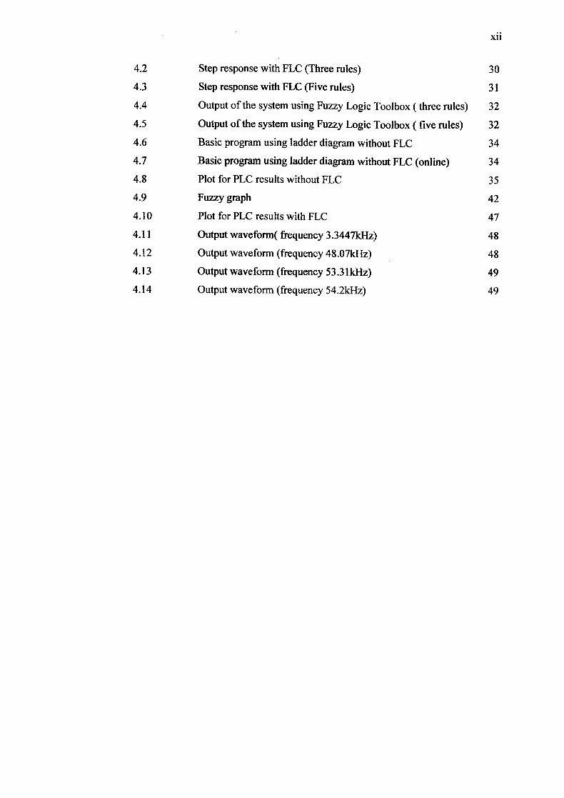
4.2 Step response with FLC (Three rules) 30
4.3 Step response with FLC (Five rules) 31
4.4 Output of the system using Fuzzy Logic Toolbox (three rules) 32
4.5 Output of the system using Fuzzy Logic Toolbox(five rules) 32
4.6 Basic program using ladder diagram without PLC 34
4.7 Basic program using ladder diagram without FLC (online) 34
4.8 Plot for PLC results without PLC 35
4.9 Fuzzy graph 42
4.10 Plot for PLC results with FLC 47
4.11 Output waveform( frequency 3.3447kHz) 48
4.12 Output waveform (frequency 48.07kHz) 48
4.13 Output waveform (frequency 53.31kHz) 49
4.14 Output waveform (frequency 54.2kHz) 49
CHAPTER 1
INTRODUCTION
1.1 Overview
Any controller design for any system commonly needs some knowledge
about the system before it will be developed. This involves a mathematical
description of the relation among inputs to the process, its variables and its output,
that is called the model of the system. The model can be represented as a set of
transfer functions, which is usually called mathematical modeling. Modeling for the
complex systems can be a very difficult task. For example, in a complex system such
as a multiple inputs and multiple outputs system, the inaccurate models will cause
the systems is unstable or has a bad system performance.
Fuzzy logic control is an effective alternative approach for systems which are
difficult to model. It is a digital control methodology that allows the human
description of the physical system, which required control strategy to be simulated in
a reasonably natural way [2]. Using fuzzy logic has avoided the need for a precise
mathematical model of the control system. It uses membership functions to define
the degree to which crisp physical values belong to a set of terms in a linguistic
variable set. That is the reason on why fuzzy logic control is widely used in
2
engineering field especially in control, modeling, image/signal processing and expert
systems.
1.2 Objective
The main aspect of intelligent control addressed in this thesis is the design of
a controller for controlling the position of ac motor by using PLC. The position of
single phase ac motor of UMP mini conveyor will be controlled by using FLC. The
PLC will act to minimize the error and make the motor stop at the required position.
1.3 Scope
The scope of this project is to build a FLC system with the main contribution
is fuzzy algorithm. Secondly is to demonstrate using PLC and single phase ac motor.
The third scope focused to control the motor rotating based on the desired set point
by the user with minimum error.
1.4 Problem Statement
The position control of ac motor is very difficult when it is done by using
traditional control techniques, as it requires a very complex mathematical model. By
using fuzzy logic, we can eliminate the need for the mathematical modeling and
allows easy realization as a solution. In this project, the fuzzy logic is implemented
into PLC because it offers the easier way to troubleshoot a system compared to the
system using microprocessor, microcontroller or other controllers. With this
3
advantage, the men in charge do not have to troubleshoot the system from a scratch
when there is system problems happen. Besides that, PLC uses ladder diagram,
which is easier to handle and manage by most people.
1.5 Thesis Organization
This thesis consists of five chapters including this chapter. The contents of
each chapter are outlined as follows;
Chapter 2 contains a detailed description on the FLC. It will explain about the
process in fuzzy logic control, which is fuzzification, fuzzy inference system and
defuzzification.
Chapter 3 includes the project methodology. This will explain how the
project is organized and the flow of the process in completing this project.
Chapter 4 presents the result of simulation runs using Fuzzy Logic Toolbox
and MATLAB SIMUL1NK.
Finally the conclusions for this project are presented in Chapter 5.
CHAPTER 2
LITERATURE REVIEW
2.1 Introduction
The first FLC was invented by Professor E.H. Mamdani at the University of
London in 1974.The controller was designed for a plant which comprised a steam
engine and boiler combination. The model of the plant had two inputs: the heat input
to the boiler and the throttle opening at the input of the engine cylinder, and two
outputs: the steam pressure in the boiler and the speed of the engine. The problem in
classical control was that the plant model was highly nonlinear with both magnitude
and polarity of the input variables [15]. This is the reason behind the fuzzy logic
found.
However, the concept and theoretical foundation of fuzzy control and
systems had been developed by Professor Lotfi Zadeh a few years earlier, which is in
1965. There are a few steps that must be followed in order to develop a FLC. First,
the actual inputs and output and their universe of discourse range is defined. Next,
the scale factors are set for input and output variable. The next step is to define the
fuzzy membership functions to be used in setting up the fuzzy sets for each input and
output variables. Then, the fuzzy control rule base or fuzzy inference mechanism is
5
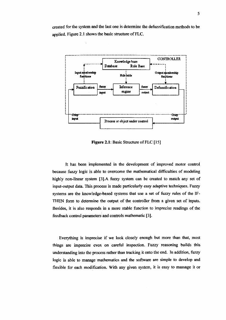
created for the system and the last one is determine the defuzzjficat ion methods to be
applied. Figure 2.1 shows the basic structure of FLC.
-----------------------------------1
CONTROLLER I Knowledge base I
Database Rule Base
o.ip
Fuzzification
ftions Ru2tab1e
Process or object under control
Figure 2.1: Basic Structure of FLC [15]
It has been implemented in the development of improved motor control
because fuzzy logic is able to overcome the mathematical difficulties of modeling
highly non-linear system [3].A fuzzy system can be created to match any set of
input-output data. This process is made particularly easy adaptive techniques. Fuzzy
systems are the knowledge-based systems that use a set of fuzzy rules of the IF-
THEN form to determine the output of the controller from a given set of inputs.
Besides, it is also responds in a more stable function to imprecise readings of the
feedback control parameters and controls mathematic [3].
Everything is imprecise if we look closely enough but more than that, most
things are imprecise even on careful inspection. Fuzzy reasoning builds this
understanding into the process rather than tracking it onto the end. In addition, fuzzy
logic is able to manage mathematics and the software are simple to develop and
flexible for each modification. With any given system, it is easy to massage it or
I p
Inference fiu2V ,l Defuzzification _______ I p
I I'
engine Ioutput I I, I, I, I, I, II I p I, I, I p I,
layer more functionality on top of it without starting again from scratch. The fuzzy
logic control approach was chosen to achieve a very short implementation time, high
robustness towards the effects of temperature and saturation and good lead and
disturbance behavior [3]. In addition, fuzzy logic is based on the natural language.
The basis for fuzzy logic is the basis for human communication. This observation
includes in many of the other statements about fuzzy logic.
As mentioned before, fuzzy logic operations can be divided into three steps. The
first one is fuzzification, whereby the actual inputs are fu.zzified and fuzzy inputs are
obtained. Secondly, fuzzy processing, which process the fuzzy inputs according to
the rules set and produce fuzzy outputs and the last step is defuzzification, which
produce a crisp real value for a fuzzy output.
2.2 Fuzzy Inference System
The inference engine is the heart of a FLC. The fuzzy inference systems are
the knowledge-based systems that use a set of fuzzy rules of the if-THEN form to
determine the output of the controller from a given set of inputs [3].
It is the actual process of mapping from a given input to an output using
fuzzy logic. The mapping then provides a basis from which decisions can be made. It
can contain the elements with only a partial degree of membership. In this project,
Fuzzy Logic Toolbox in MATLAB and SIMULINK has been used to build the initial
experimental of fuzzy inference system. In general, there are five parts of the fuzzy
inference process. The fuzzy inference process consists of fuzzy set definition,
fuzzification, rule base, fuzzy operators, implication, aggregation and
def'uzzification.
7
2.2.1 Fuzzy Set Definition
Before developing PLC, the universe of discourse must be identified and
fuzzy sets also must be defined. The definition of these Sets requires expert
knowledge of the control system. The shape of the membership function is also
determined at this step. The most common shape of membership function is
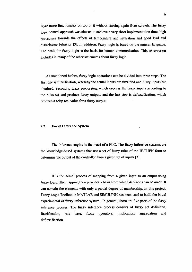
triangular. In this project, triangular shape of membership function is used. Figure
2.2 shows an example of triangular shape for the membership function MIN, MED
and MAX.
LABEL
N, MI1IBER- MAX MED MIN MBERSHIP
SHIP DEGREE 1 A A
FTJNCION
A./0.5
C SO
4
UNIVERSE OFDISCOURSE
Figure 2.2: Triangular Shape of Membership Function
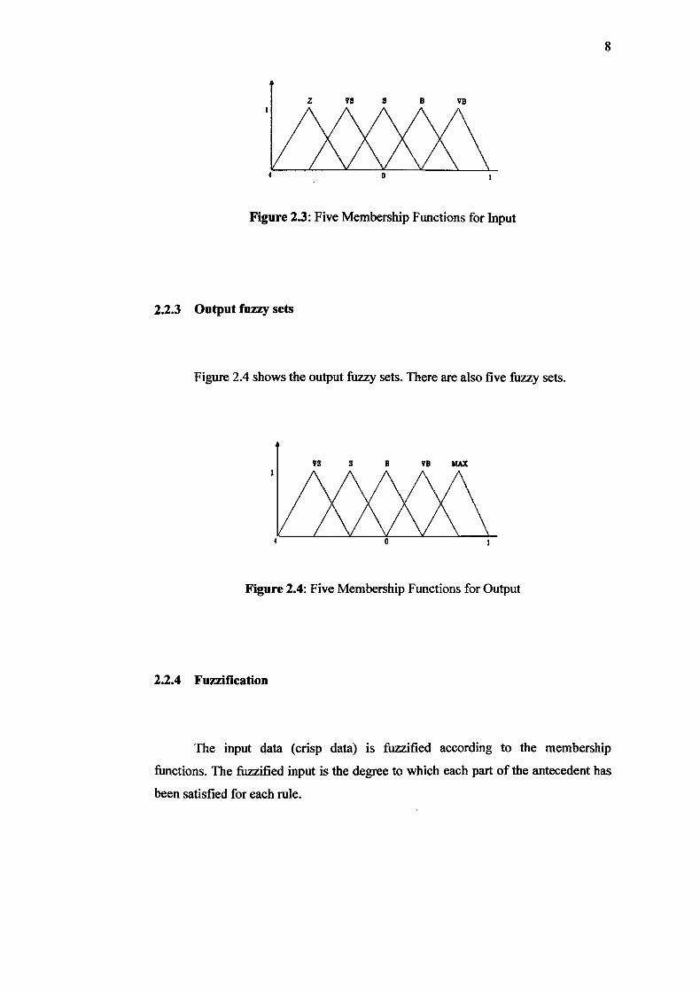
2.2.2 Input fuzzy sets
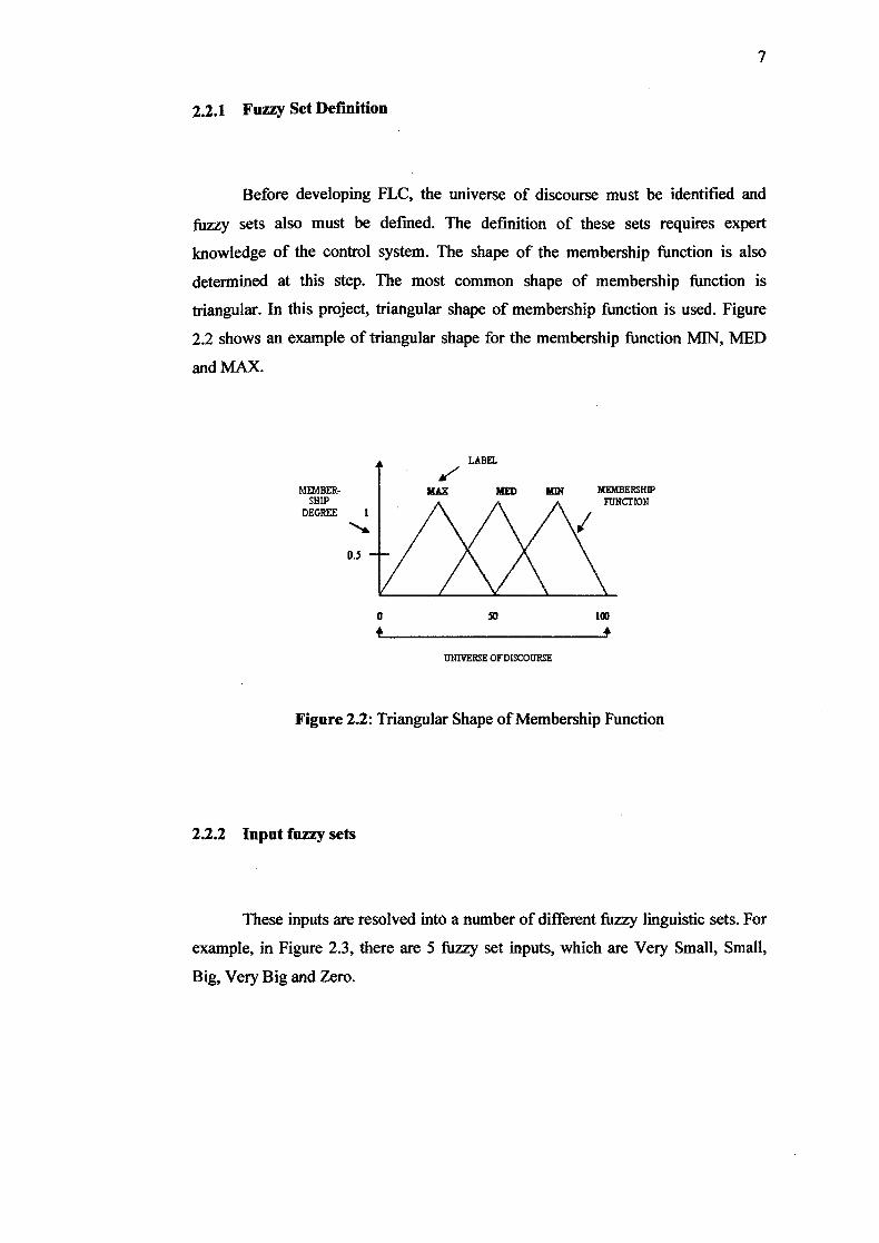
These inputs are resolved into a number of different fuzzy linguistic sets. For
example, in Figure 2.3, there are 5 fuzzy set inputs, which are Very Small, Small,
Big, Very Big and Zero.
1 0 1
F]
Figure 2.3: Five Membership Functions for Input
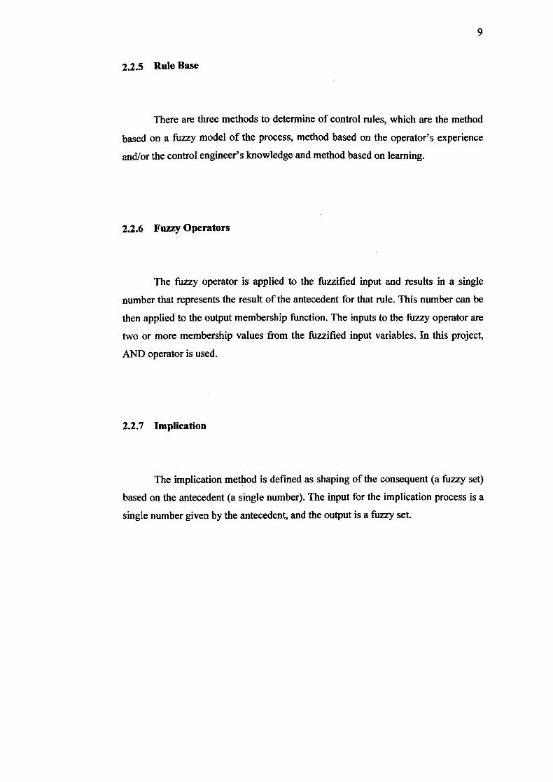
2.23 Output fuzzy sets
Figure 2.4 shows the output fuzzy sets. There are also five fuzzy sets.
8
Figure 2.4: Five Membership Functions for Output
2.2.4 Fuzzification
The input data (crisp data) is fuzzified according to the membership
functions. The fuzzified input is the degree to which each part of the antecedent has
been satisfied for each rule.
9
2.2.5 Rule Base
There are three methods to determine of control rules, which are the method
based on a fuzzy model of the process, method based on the operator's experience
and/or the control engineer's knowledge and method based on learning.
2.2.6 Fuzzy Operators
The fuzzy operator is applied to the fuzzilied input and results in a single
number that represents the result of the antecedent for that rule. This number can be
then applied to the output membership function. The inputs to the fuzzy operator are
two or more membership values from the fuzzified input variables. In this project,
AND operator is used.
2.2.7 Implication
The implication method is defined as shaping of the consequent (a fuzzy set)
based on the antecedent (a single number). The input for the implication process is a
single number given by the antecedent, and the output is a fuzzy set.
10
2.2.8 Aggregation
Aggregation is the method for unifying the outputs of each rule by joining the
parallel threads. In this process all the output fuzzy sets from each rule are united
into one fuzzy set.
2.2.9 Defuzzification
The input for defuzzification is the fuzzy set and the output is a crisp value.
This process can be obtained using six known ways, which are mean of maxima,
first-of-maxima, center-of-gravity/area, center-of-largest area, middle-of-maxima
and height defuzzification. Centroidal defuzzification method (center of gravity
method) is perhaps the most popular method is used for defuzzification. The
equation for calculating the output using this method is;
U. =
U (Ui)
Where Uo is determined by means of gravity center of the area under the
membership function curve of the fuzzy output and U (Ui) is a membership grade of
Ui.
11
2.3 PLC
PLC is used primarily to replace relays, timers and counters. The updating
process for these facilities for the yearly model change-over were very time
consuming and expensive, as the relay systems needed to be rewired by skilled
electricians. In 1968, the automatic transmission division of General Motors, which
is known as GM Hydramatic issued a request for proposal for an electronic
replacement for hard-wired relay systems [13]. The successes proposal came from
Bedford Associates of Boston, Massachusetts. Then, the first PLC is designed and
named as 084 because it was Bedford Associates eighty-fourth project. Bedford
Associates started a new company dedicated in developing, manufacturing, selling,
and servicing a new product called Modicon, which is stand for Modular Digital
Controller. One of the people who worked on that project was Dick Morley, who is
considered to be the "father" of the PLC. The Modicon brand was sold in 1977 to
Gould Electronics, and later acquired by German Company AEG and then by
Schneider Electric, the current owner [13].
Nowadays, electricity has been used for control and early electrical control
was based on relays. These relays allow the power to be switched on and off without
a mechanical switch. It is common to use relays to make simple logical control
decisions. The development of low cost computer has brought PLCs revolution as
mentioned before and now, it has become the most common choice for
manufacturing controls and motor controls. They have gained popularity in
engineering field because of the advantages they offers.
One of the advantages is an effective cost for controlling complex systems.
Secondly, it is flexible and can be reapplied to control other systems quickly and
easily. Besides, its computational abilities and trouble shooting aids allow more
sophisticated control and make programming easier while reduce downtime.
12
2.4 Single Phase Ac Motor
Various market analyses shows that 90% of all industrial motor applications
use induction type motors [6]. There are many reasons for this analysis includes
reliability, cheaper, more rugged, maintenance free, high efficiency, which is up to
80% higher and are most common in-medium-to high power applications involving
fairly constant speed operation.
Of late, much effort has been invested in developing improved control
methods for ac motors, and significant progress is seen in this area. Today's ac
motors and their advanced drive systems with frequency control and field feedback
compensation. However, the used of induction motors has several disadvantages
which is difficult controllability due to the complex mathematical model of the
motors, their nonlinear behavior during saturation and oscillations of the electrical
parameters due to the physical influence of the temperature. That is the reason on
why fuzzy logic approach is the most preferable solution in motor controls.
In this project, a single-phase ac motor will be used because of its advantages
of simplicity and low cost. The stator of a single-phase motor has only one set of
drive windings (with two or more stator poles) excited by a single-phase ac supply. If
the rotor is running close to the frequency of the line ac, this single phase can
maintain the motor torque, operating as an induction motor.
CHAPTER 3
METHODOLOGY
3.1 Introduction
This chapter presents the methodology of this project. It describes on how the
project is organized and the flow of the steps in order to complete this project. The
methodology is diverged in two parts, which is simulations using Fuzzy Logic
Toolbox and MATLAB SIMUL1NK. The other is developing the real project by
implementing the fuzzy logic into PLC.
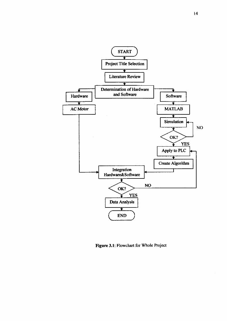
3.2 Methodology
There are three mains method in order to develop this project. Before the real
project is developing using PLC, it is need to be simulated using Fuzzy Logic
Toolbox and MATLAB SIMUL1NK. The flowchart in Figure 3.1 illustrated the
sequence of steps for this project.
START
Project Title Selection
Literature Review
IFT
Determination of Hardware
Hardware I and Software Software
14
AC Motor MATLAB
Simulation
NO
YES <*^—s
Apply to PLC
Create Algorithm
Integration Hardware&Software
OK?NO
Data Analysis
END
Figure 3.1: Flowchart for Whole Project
15
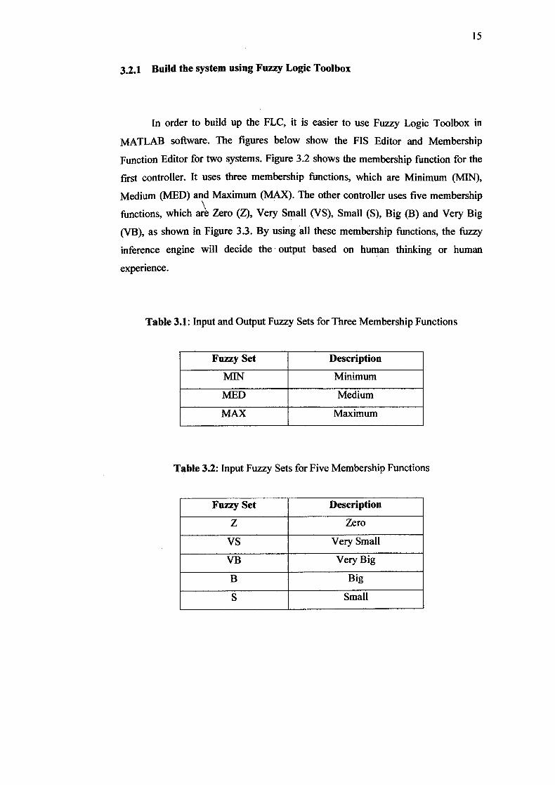
3.2.1 Build the system using Fuzzy Logic Toolbox
In order to build up the FLC, it is easier to use Fuzzy Logic Toolbox in
MATLAB software. The figures below show the FIS Editor and Membership
Function Editor for two systems. Figure 3.2 shows the membership function for the
first controller. It uses three membership functions, which are Minimum (MIN),
Medium (MED) and Maximum (MAX). The other controller uses five membership
functions, which ar Zero (Z), Very Small (VS), Small (S), Big (B) and Very Big
(VB), as shown in Figure 3.3. By using all these membership functions, the fuzzy
inference engine will decide the output based on human thinking or human
experience.
Table 3.1: Input and Output Fuzzy Sets for Three Membership Functions
Fuzzy Set Description
MIN Minimum
MED Medium
MAX Maximum
Table 3.2: Input Fuzzy Sets for Five Membership Functions
Fuzzy Set Description
Z Zero
VS Very Small
VB Very Big
B Big
S Small