universiti teknikal malaysia melaka a mechanical...
TRANSCRIPT
UNIVERSITI TEKNIKAL MALAYSIA MELAKA
A MECHANICAL STUDY ON COCOA HUSK – GLASS FIBRE/
POLYPROPYLENE (PP) HYBRID COMPOSITE
Thesis submitted in accordance with the requirements of the Universiti Teknikal
Malaysia Melaka for the Degree of Bachelor of Engineering (Honours)
Manufacturing (Engineering Material)
By
INTAN SALAFINAS BT AHMAD
Faculty of Manufacturing Engineering
April 2009
UTeM Library (Pind.1/2007)
UNIVERSITI TEKNIKAL MALAYSIA MELAKA
BORANG PENGESAHAN STATUS LAPORAN PSM
JUDUL: A MECHANICAL STUDY ON COCOA HUSK – GLASS FIBRE/ POLYPROPYLENE
(PP) HYBRID COMPOSITE
SESI PENGAJIAN: 2008/2009
Saya INTAN SALAFINAS BT AHMAD____________________________________
mengaku membenarkan laporan PSM / tesis (Sarjana/Doktor Falsafah) ini disimpan di Perpustakaan Universiti Teknikal Malaysia Melaka (UTeM) dengan syarat-syarat kegunaan seperti berikut:
1. Laporan PSM / tesis adalah hak milik Universiti Teknikal Malaysia Melaka dan penulis.
2. Perpustakaan Universiti Teknikal Malaysia Melaka dibenarkan membuat salinan untuk tujuan pengajian sahaja dengan izin penulis.
3. Perpustakaan dibenarkan membuat salinan laporan PSM / tesis ini sebagai bahan pertukaran antara institusi pengajian tinggi.
4. *Sila tandakan (√)
SULIT
TIDAK TERHAD
(Mengandungi maklumat yang berdarjah keselamatan atau kepentingan Malaysia yang termaktub di dalam AKTA RAHSIA
RASMI 1972)
(Mengandungi maklumat TERHAD yang telah ditentukan oleh
organisasi/badan di mana penyelidikan dijalankan)
* Jika laporan PSM ini SULIT atau TERHAD, sila lampirkan surat daripada pihak organisasi berkenaan
dengan menyatakan sekali sebab dan tempoh tesis ini perlu dikelaskan sebagai SULIT atau TERHAD.
i
ABSTRACT
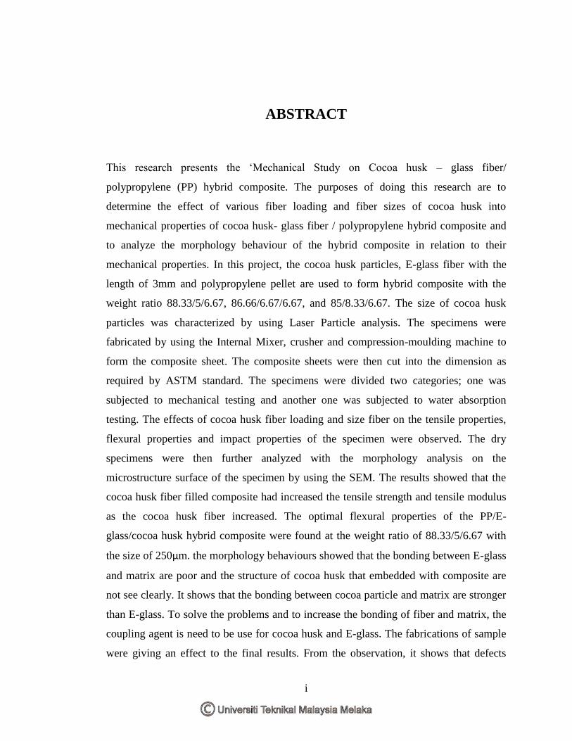
This research presents the ‘Mechanical Study on Cocoa husk – glass fiber/
polypropylene (PP) hybrid composite. The purposes of doing this research are to
determine the effect of various fiber loading and fiber sizes of cocoa husk into
mechanical properties of cocoa husk- glass fiber / polypropylene hybrid composite and
to analyze the morphology behaviour of the hybrid composite in relation to their
mechanical properties. In this project, the cocoa husk particles, E-glass fiber with the
length of 3mm and polypropylene pellet are used to form hybrid composite with the
weight ratio 88.33/5/6.67, 86.66/6.67/6.67, and 85/8.33/6.67. The size of cocoa husk
particles was characterized by using Laser Particle analysis. The specimens were
fabricated by using the Internal Mixer, crusher and compression-moulding machine to
form the composite sheet. The composite sheets were then cut into the dimension as
required by ASTM standard. The specimens were divided two categories; one was
subjected to mechanical testing and another one was subjected to water absorption
testing. The effects of cocoa husk fiber loading and size fiber on the tensile properties,
flexural properties and impact properties of the specimen were observed. The dry
specimens were then further analyzed with the morphology analysis on the
microstructure surface of the specimen by using the SEM. The results showed that the
cocoa husk fiber filled composite had increased the tensile strength and tensile modulus
as the cocoa husk fiber increased. The optimal flexural properties of the PP/E-
glass/cocoa husk hybrid composite were found at the weight ratio of 88.33/5/6.67 with
the size of 250µm. the morphology behaviours showed that the bonding between E-glass
and matrix are poor and the structure of cocoa husk that embedded with composite are
not see clearly. It shows that the bonding between cocoa particle and matrix are stronger
than E-glass. To solve the problems and to increase the bonding of fiber and matrix, the
coupling agent is need to be use for cocoa husk and E-glass. The fabrications of sample
were giving an effect to the final results. From the observation, it shows that defects
ii
such as bubbles, impurity and unmelted material were decreased the ability of the
composite materials.
iii
ABSTRAK
Kertas kerja ini menerangkan mengenai projek bertajuk ‘Kajian mekanikal pada
komposit hibrid pada gentian koko- kaca-E/polipropelene (PP)’. Tujuan menjalankan
kajian ini adalah untuk menentukan kesan perbezaan sifat mekanikal pada PP/kaca-E
komposit jika serbuk koko ditambah dengan peratus pengisian yang berbeza dan
mengkaji sifat morfologi pada PP/kaca-E/ koko komposit hybrid pada nisbah berat ;
88.33/5/6.67, 86.66/6.67/6.67, dan 85/8.33/6.67. Saiz pada serbuk koko ditentukan
melalui analisis laser mikroskop. Komposit hibrid dibentukkan ke dalam kepingan
dengan menggunakan mesin pencampur dalaman, penghancur dan pemampat. Kepingan
komposit yang dihasilkan seterusnya dipotong berdasarkan dimensi yang ditetapkan
dalam ASTM. Sampel yang dihasilkan telah dibahagikan kepada dua kumpulan iaitu
ujian mekanikal dan ujian penyerapan air. Kesan-kesan setiap pengisian koko pada sifat
mekanikal seperti sifat ketegangan, sifat kelenturan dan sifat tahan kejutan pada sampel
ditentukan melalui ujian-ujian mekanikal. Kemudian, sifat morfologi menunjukkan
penambahan pengisian serbuk koko ke dalam komposit meningkatkan sifat ketegangan.
Sifat kelenturan pada komposit hibrid didapati paling optima pada nisbah berat
88.33/5/6.67 pada saiz pengisi, 250µm. sifat morfologi didapati mempunyai ikatan yang
lemah diantara kaca-E dengan matrik dan pada ikatan koko tidak kelihatan pada
permukaan komposit. Untuk mengatasi masalah ini, bahan kimia digunakan untuk
menguatkan lagi ikatan diantara kaca-E dengan matrik. Penghasilan sampel boleh
mempengaruhi kekuatan komposit. Kebanyakan daripada sampel didapati mempunyai
kecacatan seperti rongga udara, bendasing dan bahan tidak melebur sepenuhnya. Dengan
wujudnya kecacatan ini, ia akan mengurangkan kekuatan ikatan pada komposit .
iv
DECLARATION
I hereby declare that this report entitled “A MECHANICAL STUDY ON COCOA HUSK-
GLASS FIBER/ POLYPROYLENE (PP) HYBRID COMPOSITE” is the result of my own
research except as cited in the references.
Signature :
Author’s Name : INTAN SALAFINAS BT AHMAD
Date :
v
APPROVAL
This report is submitted to the Faculty of Manufacturing Engineering of UTeM as a
partial fulfillment of the requirements for the degree of Bachelor of Manufacturing
Engineering (Material).The members of the supervisory committee are as follow:
PN. INTAN SHARHIDA BT OTHMAN
(Main Supervisor)
----------------------------------
(16 APRIL 2009)
vi
ACKNOWLEDGEMENTS
First and foremost, I would like to thank the Almighty ALLAH for giving me the time
and force to successfully complete my Projek Sarjana Muda (PSM) thesis. I am indebted
to my supervisor, Mdm Intan Sharhida Bt Othman who has given me sufficient
informations, guide, etc. upon completion of my PSM thesis writing as well as
experimentation. I would also like to thank UTeM’s technician, especially Mr. Hisyam
and Mr. Azhar Shah who had given a lot of help. I would also like to thank other
lecturers who have been so cooperatively effort. In addition, thanks to my fellow friends
for their supportive effort. For those who read this technical report, thank you for
spending your precious time.
vii
TABLE OF CONTENTS
Abstract i
Abstrak iii
Declaration iv
Approval v
Acknowledgements vi
Table of Contents vii
List of Figures xi
List of Tables xiv
List of Abbreviations, Symbols, Specialized Nomenclature xv
1.0. INTRODUCTION 1
1.1 Research background
1.2 Problem statement
1.3 Objectives of the research
1.4 Scope of the research
1
3
4
4
2.0 LITERATURE REVIEW 5
2.1 Composite 5
2.1.1 Introduction
2.1.2 Matrix
2.1.2.1 Introduction
2.1.2.2 Thermoset/Thermosetting
2.1.2.3 Thermoplastic
2.1.3 Reinforcement
2.1.3.1 Introduction
2.1.4 Synthetic Fibre
2.1.4.1 Natural Fibre
2.1.5 Polymer Matrix Composite
5
6
6
7
8
8
8
9
9
11
viii
2.1.6 Hybrid Composite
2.2 Cocoa Husk Fibre
2.2.1 Introduction
2.2.2 Characteristic Of Cocoa Husk
2.2.2.1 Chemical Composition
2.2.2.2 Mechanical And Physical Of Cocoa Husk
2.3 Glass Fibre
2.3.1 Introduction
2.3.2 Characteristic Of Glass Fibre
2.3.3 Composition Of Glass Fibre
2.4 Polypropylene
2.4.1 Introduction
2.4.2 Characteristic Of Polypropylene
2.4.3 Mechanical And Physical Of Polypropylene
2.5 Natural Glass Fibre Reinforced Polymer Matrix
2.5.1 Fibre Surface Modification
2.5.2 Coupling Agent Addition
2.6 Mechanical Properties
2.6.1 Introduction
2.6.2 Tensile Strength
2.6.3 Impact Test Charpy and Izod
2.6.4 Flexural Test
2.7 Physical Properties Of Composite
2.7.1 Water Absorption
2.8 Morphology Properties Of Composite
2.8.1 Morphology Of Fibre
2.8.2 Morphology Of Effect Of The Fibre Loading On The Composite
2.8.3 Morphology Of Surface Fracture Of The Composite
12
13
13
16
16
17
18
18
18
19
20
20
20
21
22
22
24
25
25
25
26
27
28
28
29
29
30
31
ix
3.0 MATERIALS AND METHODOLOGY
3.1 Material
3.1.1 Introduction
3.1.2 Preparation of Cocoa Pod Husk
3.1.3 Polypropylene
3.1.4 E-glass
3.2. Methodology
3.2.1 Introduction
3.2.2 Raw Materials preparation
3.2.3 Hybrid Composite Fabrication
3.2.3.1 Internal Mixing Process
3.2.3.2 Crushing Process
3.2.3.3 Hot Press Process
3.2.3.4 Specimen Cutting Process
3.3 Preparation of Sample for Testing
3.3.1 Introduction
3.3.1.1 Tensile Test
3.3.1.2 Izod Pendulum Impact
3.3.1.3 Flexural Test
3.3.1.4 Water Absorption
3.4 Preparation For Analysis
3.4.1 Morphology Investigation
3.4.2 Laser Particle Analysis
33
33
33
33
35
36
37
37
40
41
41
43
45
46
46
46
46
49
51
53
53
53
55
x
4.0 RESULT AND DISCUSSION
4.1 Data Analysis
4.1.1 Introduction
4.1.1.1 Tensile Testing
4.1.1.2 Flexural Testing
4.1.1.3 Impact Testing
4.1.1.4 Water Absorption
4.2 Mechanical Properties of Size Fiber
4.3 Morphology Analysis
4.3.1 SEM Examination on Microstructure Surface
5.0 CONCLUSION AND RECOMMENDATIONS
5.1 Conclusion
5.2 Recommendation
57
57
57
57
59
61
62
64
65
65
68
68
70
REFERENCES 71
APPENDICES
Tensile Calculations
Water Absorption
Impact test
Gantt chart 1 &2
xi
LIST OF FIGURES
1 0 INTRODUCTION
2.0 LITERATURE REVIEW
2.1 Longitudinal Section Of A Cocoa Pod Showing The Physical
Featues
14
2.2 Transverse Section Of A Cocoa Pod Showing Physical
Feature
14
2.3 Flow Chart Of Cocoa Processing 15
2.4 Tensile Testing 26
2.5 Impact Test Charpy And Izod Machine 26
2.6 Flexural Test Machine 27
2.7 Standard Coir 30
2.8 SEM Micrograph Of Rom Temperature Fracture Specimen 31
2.9 Micrograph Of Specimen 32
3.0 MATERIAL & METHODOLOGY
3.1 Cocoa Bean With Surrounding By Cocoa Husk 33
3.2 Flow Step of Processing Cocoa Husk 34
3.3 Particle Size of Cocoa Husk 35
3.4 Pellet of PP 35
3.5 E-glass 36
3.6 Manufacturing Process Flow Chart 38
3.7 Pulverisettle 14 With 12 Ribs-Rotor 40
3.8 The thermal Haake Internal Mixer Machine 42
3.9 General Setting on Thermal Haake Internal Mixer Machine 42
3.10 Crusher Machine 43
3.11 Bulk Shape of Hybrid Composite 44
3.12 Blend Material After Crushing 44
xii
3.13 Hydraulic Moulding Test Press Machine 45
3.14 The Component Of Hot Press Machine 45
3.15 Cutting Process of Tensille Specimen 46
3.16 Specimen Dimension For Thickness 47
3.17 Tensile Testing (UTM) 48
3.18 Izod V-Notch Specimen
3.19 Relationship Of Vise For Izod Impact
3.20 Dimension Of Izod Specimen
3.21 Flexural Test Method
3.22 Mettler Balance Equipment
3.23 SEM Equipment
3.24 Example Of Specimen That Mounted On Sem Stubs
3.25 Laser Particle Analysis
49
50
50
52
53
54
54
55
4.0 RESULT & DISCUSSION
4.1 Tensile Strength Versus Size Fiber Of Hybrid Composite
4.2 Tensile Modulus Versus Size Fiber Of Hybrid Composite
4.3 Flexural Strength Versus Size Fiber Of Hybrid Composite
4.4 Flexural Modulus Versus Size Fiber Of Hybrid Composite
4.5 Impact Strength Versus Size Fiber Of Hybrid Composite
4.6 Weight Gain In Percentages Versus Time For Hybrid
Composite With 45µm Size Fiber
4.7 Weight Gain in Percentages Versus Time for Hybrid
Composite with 250µm Size Fiber
4.8 Weight Gain In Percentages Versus Time For Hybrid
Composite With 500µm Size Fiber
4.9 SEM Micrograph of 5 wt% of Cocoa fiber in 45µm
4.10 SEM Micrograph of 5 wt% of Cocoa fiber in 45µm
4.11 SEM Micrograph of 5 wt% of Cocoa fiber in 250µm
57
58
59
59
61
62
63
63
65
66
66
xiii
4.12 SEM Micrograph of 5 wt% of Cocoa fiber in 500µm
66
xiv
LIST OF TABLES
1 .0 INTRODUCTION
2.0 LITERATURE REVIEW
2.1 Types Of Natural Fibre And General Families 11
2.2 Composition of Chemical Of Untreated Maize Cob And
Cocoa Pod Husk
16
2.3 A Few Typical Mechanical And Physical Properties Of
Natural Fibre
17
2.4 Characteristic Of Fibre With Some Common Fibers 20
2.5 Values Of Tg And Tm For Selected Polymer 22
3.0
4.0
5.0
MATERIAL & METHODOLOGY
3.1 The Ratio Parameter For Mixture Machine
3.2 Standard Dimension For Rigid And Semirigid Plastics
RESULTS AND DISCUSSIONS
CONCLUSION & RECOMMENDATION
43
47
xv
LIST OF ABBREVIATIONS, SYMBOLS,
NOMENCLATURES
PP - Polypropylene
SEM
ASTM
- Scanning Electron Microscope
American Society of Testing Materials
1
CHAPTER 1
INTRODUCTION
1.1 Research Background
A characteristic feature of today‟s modern technology and market-oriented economy
is the excessive and exponentially increasing usage of polymer composites in all
fields of industry. The reason for this phenomenon can be explained by the
favourable price/weight ratio. The automotive industry is developing most
dynamically since a serious weight decrease can be achieved by using polymer
composites and hence fuel can be saved and damage to the environment decreases. It
is possible to make completely new types of composite materials by combining
different resources.
The objective will be to combine two or more materials in such a way that a
synergism between the components results in a new material that is better than the
individual components. One of the big new areas of development is in combining
natural fibres with thermoplastics. Since prices for plastics have risen sharply over
the past few years, adding a natural powder or fibre to plastics provides a cost
reduction to the plastic industry and in some cases increases performance as well, but
to the lignocelluloses- based industry, this represents an increased value for the
lignocelluloses-based component (Rowell et al, 1999).
Any substance such as natural fibre and other plant that contains both cellulose and
lignin is lignocelluloses. In general, wood is also in type of other lignocelluloses
even though they may differ in chemical composition and matrix morphology. The
main of composite development is to produce a new product with excellent
2
performance in characteristics that combine the positive attributes of each constituent
component. Like other lignocelluloses material, nature fibre is strong, lightweight,
abundant, nonhazardous and relatively inexpensive. Any lignocelluloses can be
chemically modified to enhance properties such as dimensional stability and
resistance to bio-deterioration. This provides a new improvement in cost and
performance of value-added from different raw materials (Gilbert et al, 1994).
The main limitation by using the lignocelluloses fibres is the lower processing
temperature permissible due to the possibility of fibre degradation and/or the
possibility of volatile emissions that could affect composite properties. The
processing temperatures are thus limited to about 200°C, although it is possible to
use higher temperatures for short periods. This processing factor limits the type of
thermo-plastics that can be used with lignocelluloses fibres; to commodity
thermoplastics such as polyethylene (PE), polypropylene (PP), polyvinyl chloride
(PVC) and poly-styrene (PS). However, it is important to note that these lower-
priced plastics constitute about 70% of the total thermoplastic consumed by the
plastics industry, and consequently the use of fillers/reinforcement presently used in
these plastics far out-weigh the use in other more expensive plastics. In the way to
make a better mix with the hydrophore (plastic) in the hydrophil (lignocelluloses),
there are two basic area; one in which no attempt is made to compatibilize the two
dissimilar resources and, a second in which a compatibilizer. In the first case, the
lignocelluloses fibre is added as relatively of low cost filler and in the second, the
lignocelluloses fibre is added as reinforce filler. Both of these types of materials are
usually referred to as natural fibre/thermoplastic blends (Rowell et al, 1999).
Several million metric tons of fillers and reinforcements are used annually by the
plastics industry. The use of these additives in plastics is likely to grow with the
introduction of improved compounding technology, and new coupling and
compatibilizing agents that permit the use of high filler/reinforcement content. As
suggested by Katz et al. (1987), fillings up to 75 parts per hundred (pph) could be
common in the future. This level of filler could have a tremendous impact in
lowering the usage of petroleum-based plastics. It would also be particularly
beneficial; both in terms of the environment and also in socioeconomic terms, if a
3
significant amount of the fillers were obtained from a renewable agricultural source
(Anand, R. et al, 1997).
1.2 Problem Statement
In worldwide, the usage of any substance of natural fibre such as wood agricultural
crops, like jute or kenaf; agricultural residues, such as bagasse or corn stallus;
grasses; and other plant substances are getting increase to produce new products.
From the wasted materials, it becomes a useful product to replace the old materials.
In manufacturing sector especially in healthy and food, the natural fibre is most
popular material usage in producing cosmetic and food for animal. Many sectors
have been use cocoa husk as the addition of ingredient. In manufacturing food
products, the cocoa husk was suggested as an ingredient in foods (Bonuchi J.S. et al,
1999).Today, the natural fibre is mostly use as addition materials for produce a
product such as cotton, recycles paper, cabinet and so on. In general, the mechanical
and physical properties of natural fibre reinforced plastic only conditionally reach the
characteristic values of glass-fibre reinforced system. By hybrid composites, in using
of natural fibre and carbon fibre/ glass fibre as the reinforcement is adding with the
polymer (Polypropylene) as a matrix the properties of natural fibre reinforced
composite.
A wasted materials are rarely use in manufacturing. Some other can be used and a
less is wasted. Cocoa husk pod is category of wasted material use in food
manufacturing cocoa. Cocoa husks, when properly processed, serve as animal feeds
and can be burnt to produce potash for making soft soap (Owolarafe, O.K, et.al,
2007).
But, now, some of researcher uses the cocoa husk for produce cosmetic and
preparation food animal. In this research, cocoa husk will use to combine the
synthetic fibre and matrix polymer to reveal the properties in mechanical and
physical. In this research, the cocoa pod husk as natural fibre will adds with glass-
fibre/polypropylene to get new mixture materials. Hence, the testing and analysis
will be done to investigate the strength of hybrid composite in mechanical and
4
physical properties. From that, the characteristics of hybrid composite can be use for
producing products that due to economic today.
1.3 Objectives
a) To investigate the effect of various fiber loading and fiber sizes of cocoa husk
into mechanical properties of cocoa husk-glass fiber/polypropylene hybrid
composite.
b) To analyze the effect of water absorption of cocoa husk-glassfiber/
polypropylene hybrid composite.
c) To investigate the morphology of cocoa husk-glassfiber/ polypropylene
hybrid composite.
1.4 Scopes
a) To prepare the sizes of cocoa husk in three types; 45µm, 250µm and 500µm.
b) To fabricate the specimen of cocoa husk-glassfiber/ polypropylene hybrid
composite.
c) To identify the feasibility of cocoa husk (wasted material) reinforced glass
fiber/polypropylene hybrid composite on impact resistance.
d) To find the strength of mechanical and physical properties on cocoa husk-
glassfiber/ polypropylene hybrid composite.
e) To identify the ability of water absorption on cocoa husk-glassfiber/
polypropylene hybrid composite.
f) To analyze the morphology of the particular composite by using Scanning
electron microscope (SEM)
5
CHAPTER 2
LITERATURE REVIEW
2.1 Composite
2.1.1 Introduction
Nowadays, the request and needs of high performances materials such as composite
are increase due to the rapid development in manufacturing. Despite the fact that
composites are generally more expensive in comparison to traditional construction
materials, and therefore not as widely used in many constructive and building
activities, they have the advantage of being lightweight, more corrosion resistant and
stronger. The fibre reinforcements provide good damping characteristics and high
resistance to fatigue. Over the last thirty years composite materials, plastics, and
ceramics have been the dominant emerging materials. The volume and number of
applications of composite materials has grown steadily, penetrating and conquering
new markets relentlessly. Modern composite materials constitute a significant
proportion of the engineered materials market.
Composite is define as a combination of two or more materials (reinforcing elements,
fillers, and composite matrix binder), differing in form or composition on a macro
scale. The constituents retain their identities, that is, they do not dissolve or merge
completely into one another although they act in concert. Normally, the components
can be physically identified and exhibit an interface between one another. Examples
are cermets and metal-matrix composites. Composite materials are constantly being
6
adapted to the way that they are used. As a result, there are a wide variety of
composites to choose from, thanks to the ever-changing technological advances that
make it possible to apply Composite Engineering. As a result, each type of composite
brings its own performance characteristics that are typically suited for specific
applications. In modern materials of engineering, the term of composite is usually
refers to a matrix material that is reinforced with fibers. For instance, the term FRP
(Fiber Reinforced Plastic) usually indicates a thermosetting polyester matrix
containing glass fibers (Roylance, 2000).
2.1.2 Matrix
2.1.2.1 Introduction
Most basic form a composite material is one, which is composed of at least two
elements working together to produce material properties that are different to the
properties of those elements on their own. In practice, most composites consist of a
bulk material matrix, and a reinforcement of some kind, added primarily to increase
the strength and stiffness of the matrix. This reinforcement is usually in fibre form.
Today, the most common man-made composites can be divided into three main
groups (Callister, 2003).
(a) Polymer Matrix Composites (PMC‟s)
PMC that consists of glass, carbon and aramid in a thermoset or thermoplastic are
provided strong, stiff and corrosion resistant. It also known as FRP Fibre Reinforced
Polymers or Plastics that use as polymer-based resin in the matrix (Anonymous 1,
2001).
(b) Metal Matrix Composites (MMC‟s)
MMC is a continuous metallic phase (matrix) where is combined with another phase
(reinforcement). Increasingly found in the automotive industry, these materials use a
metal such as aluminium as the matrix, and reinforce it with fibres such as silicon
carbide. Most of MMC exhibited such as lower density, increased specific strength
7
and stiffness, increase high temperature performance limits and improved wear
abrasion resistance (Anonymous 2, 2009).
(c) Ceramic Matrix Composites (CMC‟s)
CMC is combinations of reinforcing ceramic phases with a ceramic matrix to create
materials. This material is produced a new properties in structural part such as rocket
and jet engines. The characteristic of CMC are including high temperature, stability,
high thermal shock resistance, high hardness, and high corrosion resistance and so
on. Anyway, it used in very high temperature environments where these materials
use a ceramic as the matrix and reinforce it with short fibres, or whiskers such as
those made from silicon carbide and boron nitride (Naslain, 2009).
2.1.2.2 Termoset/ Thermosetting
Thermosetting plastics (thermosets) are polymer materials that irreversibly cure to a
stronger form. The cure may be done through heat (generally above 200 degrees
Celsius), through a chemical reaction (two-part epoxy, for example), or irradiation
such as electron beam processing. Thermoset materials are usually liquid or
malleable prior to curing and designed to be molded into their final form, or used as
adhesives. Others are solids like that of the molding compound used in
semiconductors and integrated circuits (IC's).
Thermosetting polymers become permanently hard when heat is applied and do not
soften upon subsequent heating. During the initial heat treatment, covalent crosslink
are formed between adjacent molecular chains; these bonds anchor the chains
together to resist the vibration and rotational chain motions at high temperature.
Crosslinking is usually extensive, in that 10% to 50% of the chain mer units are
crosslinked. Only heating to excessive temperature will cause severance of these
crosslink bonds and polymer degradation. Thermoset polymer is generally harder and
stronger than thermoplastics and has better dimensional stability. Thermoset may
contain filler materials such as powder or fiber to provide improved strength and
stiffness (Anonymous 3, 2009).
8
2.1.2.3 Thermoplastic
Thermoplastics soften when heated and harden when cooled-processes that are
totally reversible and may be repeated. On a molecular level, as the temperature is
raised, secondary bonding forces are diminished so that the relative movement of
adjacent chains is facilitated when a stress is applied. Irreversible degradation results
when the temperature of a molten thermoplastic polymer is raised to the point at
which molecular vibrations become violent enough to break the primary covalent
bonds. In addition, thermoplastic are relatively soft. Most linear polymers and those
having some branches structures with flexible chains are thermoplastic. These
materials are normally fabricated by the simultaneous application of heat and
pressure (Callister, 2003).
2.1.3 Reinforcement
2.1.3.1 Introduction
The characteristics of reinforcement are usually stronger and stiffer than the matrix.
The matrix holds the reinforcements in an orderly pattern. Because the
reinforcements are usually discontinuous, the matrix also helps to transfer load
among the reinforcements. Reinforcements basically come in three forms:
particulate, discontinuous fiber, and continuous fiber. Thus, the composite properties
cannot come close to the reinforcement properties. Composite properties are much
higher, and continuous fibers are therefore used in most high performance
components, be they aerospace structures or sporting goods. An important
characteristic of most materials, especially brittle ones, is that a small diameter fibre
is mush stronger than the bulk materials. The fibre phase or reinforcement is
strengthening of a relatively weak material by embedding a strong fibre phase within
the weak matrix materials. These reinforcements are often in the shape of fibre
because fibres can be made very stiff primarily in their long direction. When the fibre
long, the applied load tend to transmitted along the fibre. If short and the volume
fibre low, the mechanical properties composite is equal (Anonymous 4, 2009).
9
There are three different classification; whiskers, fibre and wires. Whiskers have
very tin single crystal structure. It also has a high length to diameter ratio. If small
size of whiskers, it have a high degree of crystalline perfection and are virtually flaw
free and high strength. Whiskers are an expensive and impractical to incorporate
whiskers into matrix. Example of whisker are; graphite, silicon carbide, aluminium
oxide, etc. Materials that are classified as fibres are either polycrystalline or
amorphous and have small diameter; fibrous materials are generally either polymers
or ceramic (e.g., the polymer aramids, glass, carbon, boron, aluminium oxide and
silicon carbide). Fines wires have relatively large diameters; typical materials include
steel, molybdenum and tungsten. Wires are utilized as a radial steel reinforcement in
automobile tires, in filament wound rocket casings, and in wire wound high pressure
hoses .
2.1.4 Synthetic Fibre
The types of synthetics fibre are; glass fibre, boron fibre, fumed silica, fused silica
and etc. There are two types of synthetic fibre products, the semisynthetics, or
celluloses (viscose rayon and cellulose acetate), and the true synthetics, or
noncellulosics (polyester, nylon, acrylic and modacrylic, and polyolefin).
Semisynthetics are formed from natural polymeric materials such as cellulose. True
synthetics are products of the polymerization of smaller chemical units into long-
chain molecular polymers
2.1.4.1 Natural Fibre
A fibre obtained from a plant, animal, or mineral. The commercially important
natural fibres are those cellulose fibres obtained from the seed hairs, stems, and
leaves of plants; protein fibres obtained from the hair, fur, or cocoons of animals; and
the crystalline mineral asbestos. Until the advent of the manufactured fibres near the
beginning of the twentieth century, the chief fibres for apparel and home furnishings
were linen and wool in the temperate climates and cotton in the tropical climates.
However, with the invention of the cotton gin in 1798, cheap cotton products began
10
to replace the more expensive linen and wool until by 1950 cotton accounted for
about 70% of the world's fibre production. Despite the development of new fibres
based on fossil fuels, cotton has managed to maintain its position as the fibre with the
largest production volume in the industries.
The natural fibres may be classified by their origin as cellulose (from plants), protein
(from animals), and mineral. The plant fibres may be further ordered as seed hairs,
such as cotton; bast (stem) fibres, such as linen from the flax plant; hard (leaf) fibres,
such as sisal; and husk fibres, such as coconut. The animal fibres are grouped under
the categories of hair, such as wool; fur, such as angora; or secretions, such as silk.
The only important mineral fibre is asbestos, which because of its carcinogenic
nature has been banned from consumer textiles. The most used natural fibres are
cotton, flax and hemp, although sisal, jute, kenaf, and coconut are also widely used.
Hemp fibres are mainly used for ropes and aerofoils because of their high suppleness
and resistance within an aggressive environment. Hemp fibres are, for example,
currently used as a seal within the heating and sanitary industries.
The use of natural fibres at the industrial level improves the environmental
sustainability of the parts being constructed, especially within the automotive market.
Within the building industry, the interest in natural fibres is mostly economical and
technical; natural fibres allow insulation properties higher than current materials.
Natural fibres are rapidly emerging in composites applications that glass fibres
(predominantly E-glass) have been traditionally used. This is particularly true within the
automotive and construction industries. These natural fibres provide several benefits: low
cost, “green” availability, lower densities, and recyclable, biodegradable, moderate
mechanical properties, abundant. Their uses have found entry into booth the thermoset and
thermoplastic composites market places. Industries are rapidly learning to analysis
effectively process these natural resources and use them in numerous composites
applications.
Typically they are used with well-recognized thermoset resin families: polyesters, vinyl
esters and epoxies. Thermoplastics resin matrices also are those commonly seen within the
commercial markets: polypropylene, low density polyethylene (LDPE), high density
polyethylene (HDPE), polystyrene, Nylon 6 and Nylon 6,6 systems. Soy based resin systems
also are coming into vogue in some applications as been learn more about its chemistry and
11
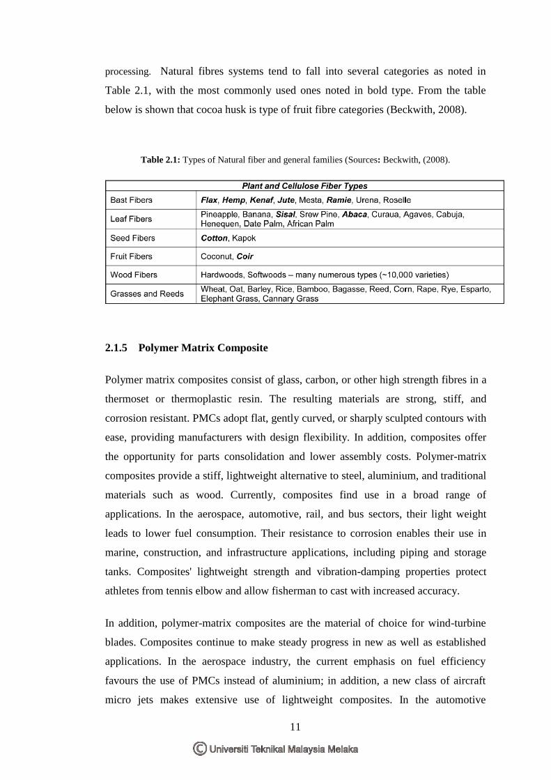
processing. Natural fibres systems tend to fall into several categories as noted in
Table 2.1, with the most commonly used ones noted in bold type. From the table
below is shown that cocoa husk is type of fruit fibre categories (Beckwith, 2008).
Table 2.1: Types of Natural fiber and general families (Sources: Beckwith, (2008).
2.1.5 Polymer Matrix Composite
Polymer matrix composites consist of glass, carbon, or other high strength fibres in a
thermoset or thermoplastic resin. The resulting materials are strong, stiff, and
corrosion resistant. PMCs adopt flat, gently curved, or sharply sculpted contours with
ease, providing manufacturers with design flexibility. In addition, composites offer
the opportunity for parts consolidation and lower assembly costs. Polymer-matrix
composites provide a stiff, lightweight alternative to steel, aluminium, and traditional
materials such as wood. Currently, composites find use in a broad range of
applications. In the aerospace, automotive, rail, and bus sectors, their light weight
leads to lower fuel consumption. Their resistance to corrosion enables their use in
marine, construction, and infrastructure applications, including piping and storage
tanks. Composites' lightweight strength and vibration-damping properties protect
athletes from tennis elbow and allow fisherman to cast with increased accuracy.
In addition, polymer-matrix composites are the material of choice for wind-turbine
blades. Composites continue to make steady progress in new as well as established
applications. In the aerospace industry, the current emphasis on fuel efficiency
favours the use of PMCs instead of aluminium; in addition, a new class of aircraft
micro jets makes extensive use of lightweight composites. In the automotive
12
industry, manufacturers are recognizing the advantages of weight reduction, parts
consolidation, and design freedom that PMCs afford. In the energy sector, the
growing use of wind energy has led to increased demand for PMC turbine blades
(Anonymous 1, 2001).
2.1.6 Hybrid Composite
A relatively new fibre-reinforced composite is the hybrid, which is obtained by using
two or more different kinds of fibres in a single matrix; hybrids have a better all-
round combination of properties than composites containing only a single fibre type.
A variety of fibre combinations and matrix materials are used, but in the most
common system, both carbon and glass fibre are incorporated into a polymeric resin.
Hybrids contain a range of particle sizes ranging from 0.6 to 1 micrometer.
Developed in the late 1980's, these composites achieve between 70 to 75 percent by
weight of filler particles. The first generation hybrids achieved excellent wear
characteristics which made them acceptable as posterior filling materials. They also
had fair polishability. The second generation of hybrids achieved greater
polishability and superior colour optics by using uniformly cut small filler particles
between the larger particles, as well as resin hardeners which help to maintain a
surface polish during prolonged function.
Hybrids also have unique colour reflecting characteristics which gives them a
chameleon-like appearance. In other words, these materials are able to emit their
own colour as well as absorb colour from the surrounding and underlying tooth
structure. Hybrid composites are today the workhorse of the modern dentist. They
are used in nearly all anterior restorations, and are becoming commonplace in
posterior restorations as well (Anonymous 5, 2009).
13
2.2 Cocoa Husk Fibre
2.2.1 Introduction
The Malaysian Cocoa Board (MCB) is a federal statutory research and development
agency under the Ministry of Plantation Industries and Commodities (previously
called Ministry of Primary Industries Malaysia). It was established under the Act of
Parliament 343 (incorporation) in 1988 and has been in operation since 1989. The
main objective is to develop the cocoa industry in Malaysia to be well integrated and
competitive in the global market. Emphasis is given to increasing productivity and
efficiency in cocoa bean production and increasing downstream activities.
Cocoa, the nectar of the gods and even the cocoa tree's botanical name, 'Theobroma
cacao' translated from the Greek means "food of the gods" has a history rooted in the
mists of time as far back as 1662. In the early days, the native belief that cocoa tree
was of divine origin and resulted in a holy ritual being performed whenever cocoa
trees were planted. The cocoa tree can grow to between 12 to 15 m high in the wild,
and up to 4 to 5 m in cultivated form. It bears fruit or pods that contain cocoa beans,
which when fermented and dried, provide valuable material for all chocolate-based
products ranging from beverages and confectionaries to cosmetics.
Cocoa has successfully conquered all countries and continents of the world in just
over 500 years since its first discovery in the ancient civilization of the Mayas and
Aztecs in South America. In Malaysia, the first cocoa planted area was found in
Malacca in 1778. Subsequently, the cocoa planting was started in a plotted area at
Serdang Agriculture Station and Silam Agriculture Research Centre, Sabah. The
earliest cocoa commercialization started from 1853 to 1959 where cocoa types
Amelonado was first planted at Jerangau, Terengganu. The planted area was 403
hectarages. Cocoa trial was further undertaken at Serdang, Cheras, Kuala Lipis and
Temerloh from 1936 to 1940. However, cocoa was only actively planted after World
War II. Cocoa officially came to Quoin Hill, Tawau, Sabah in 1960. From then on,
there was no turning back to cocoa fever (Anonymous 6, 2004).
14
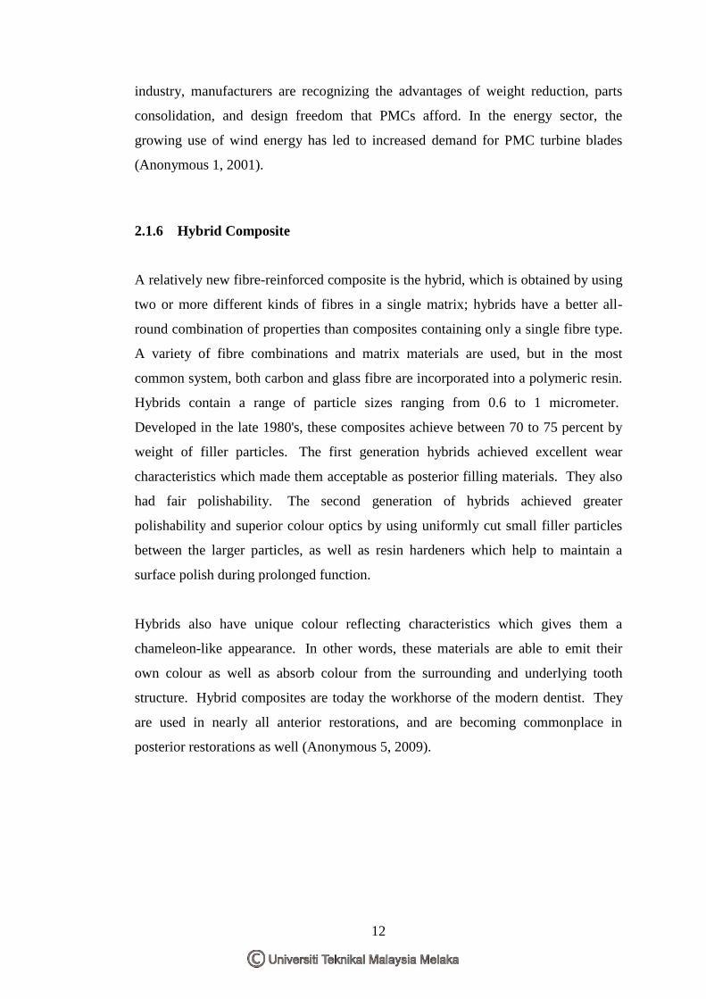
Figure 2.1: Longitudinal section of a cocoa pod showing the physical features (section y-y)
(Source: Owolarafel et.al, 1997)
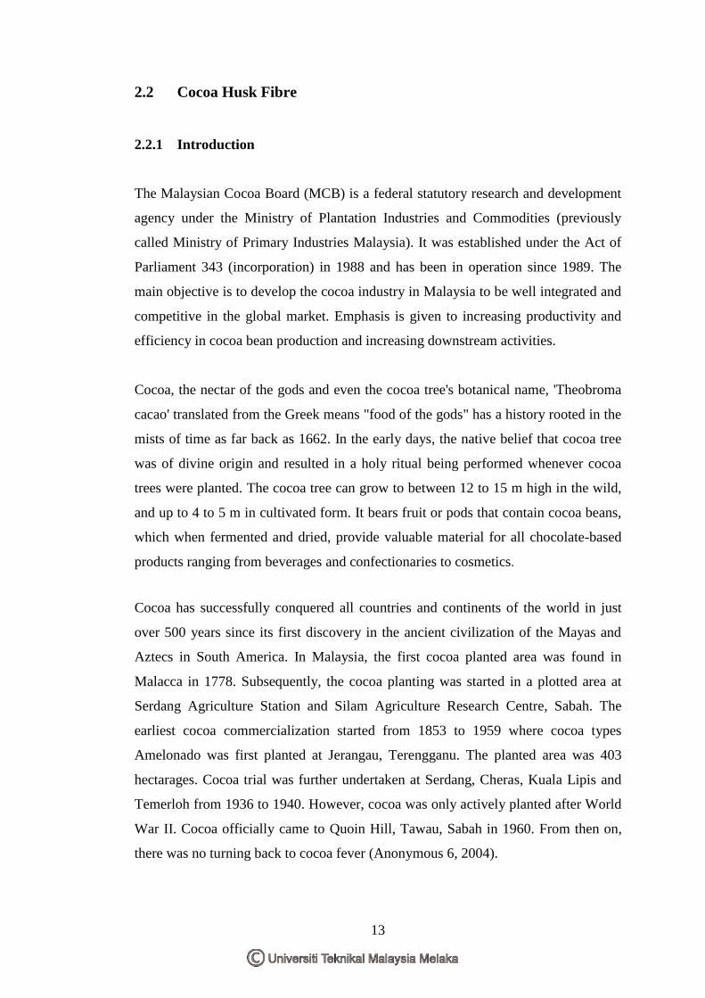
Figure 2.2: Transverse section of a cocoa pod showing the physical features (section x-x)
(Source: Owolarafel et.al, 1997)
The physical structure of a longitudionally and transversely sectioned cocoa pod is
shown in figure 2.1 and figure 2.2 (Owolarafe1, 1997). A cocoa pod is approximately
20 cm long and 10 cm wide. A section through the pod shows a rough leathery rind
about 3 cm thick, filled with sweet (although not edible), slimy and pinkish pulp,
enclosing from 30 to 50 large, soft, pink or purple almond-like seeds or beans.
Among most commercial crops, cocoa is known to provide very high economic
15
returns because of the wide range of domestic and industrial uses of the beans. Cocoa
pulp juice is used in the production of soft drinks and alcohol. Cocoa husks, when
properly processed, serve as animal feeds and can be burnt to produce potash for
making soft soap (Owolarafe et al, 2007).
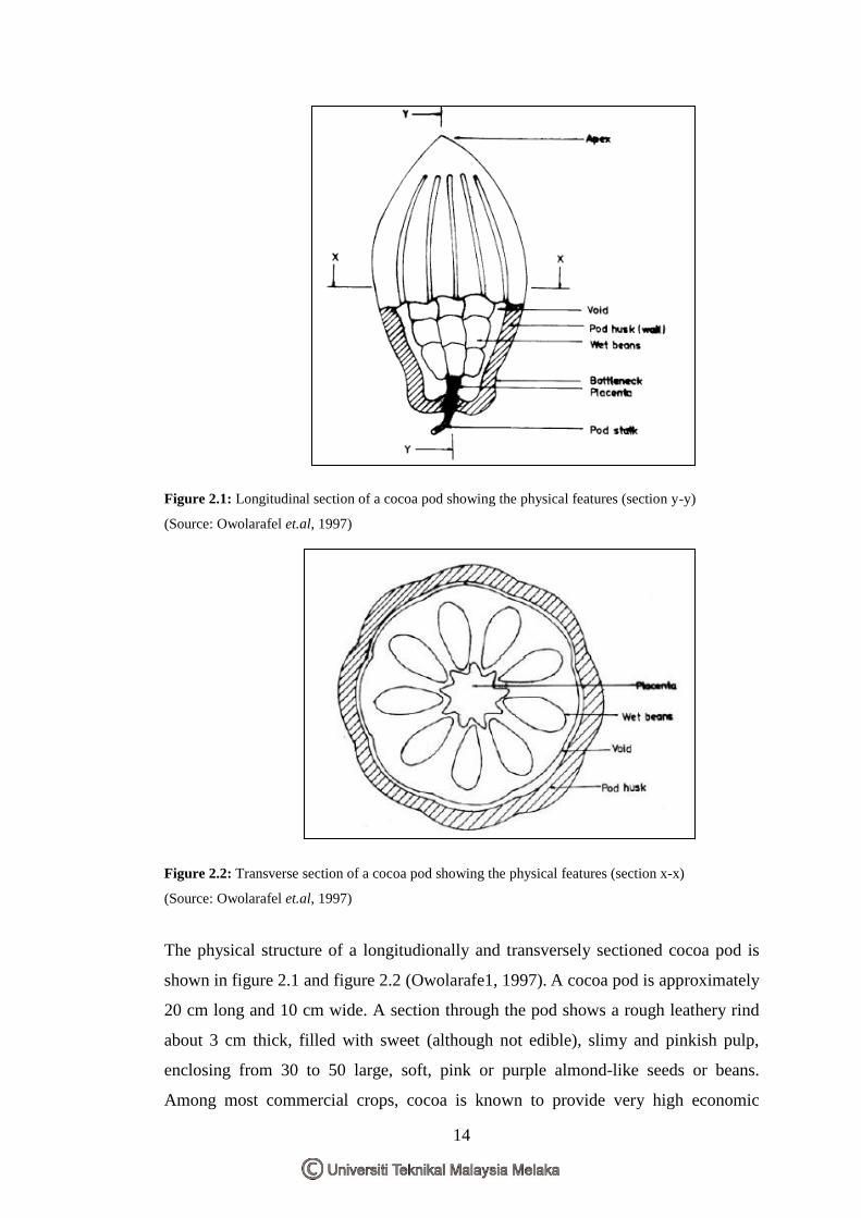
Figure 2.3: Flowchart of cocoa processing. (Source: Owolarafel et.al, 1997).
In most places, especially in Africa, harvesting is done manually with go-to-hell and
is therefore a labor-intensive operation. Cocoa bean extraction (i.e., breaking the
pods and separating the wet beans from the husks) is the first step in cocoa pod
processing (see Figure 2.3) which is traditionally manual. Pods are broken with
objects such as wooden clubs, cutlasses and knives to hit or strike the pods or by
knocking two pods against each other laterally.
16
2.2.2 Characteristic Of Cocoa Husk
2.2.2.1 Chemical composition
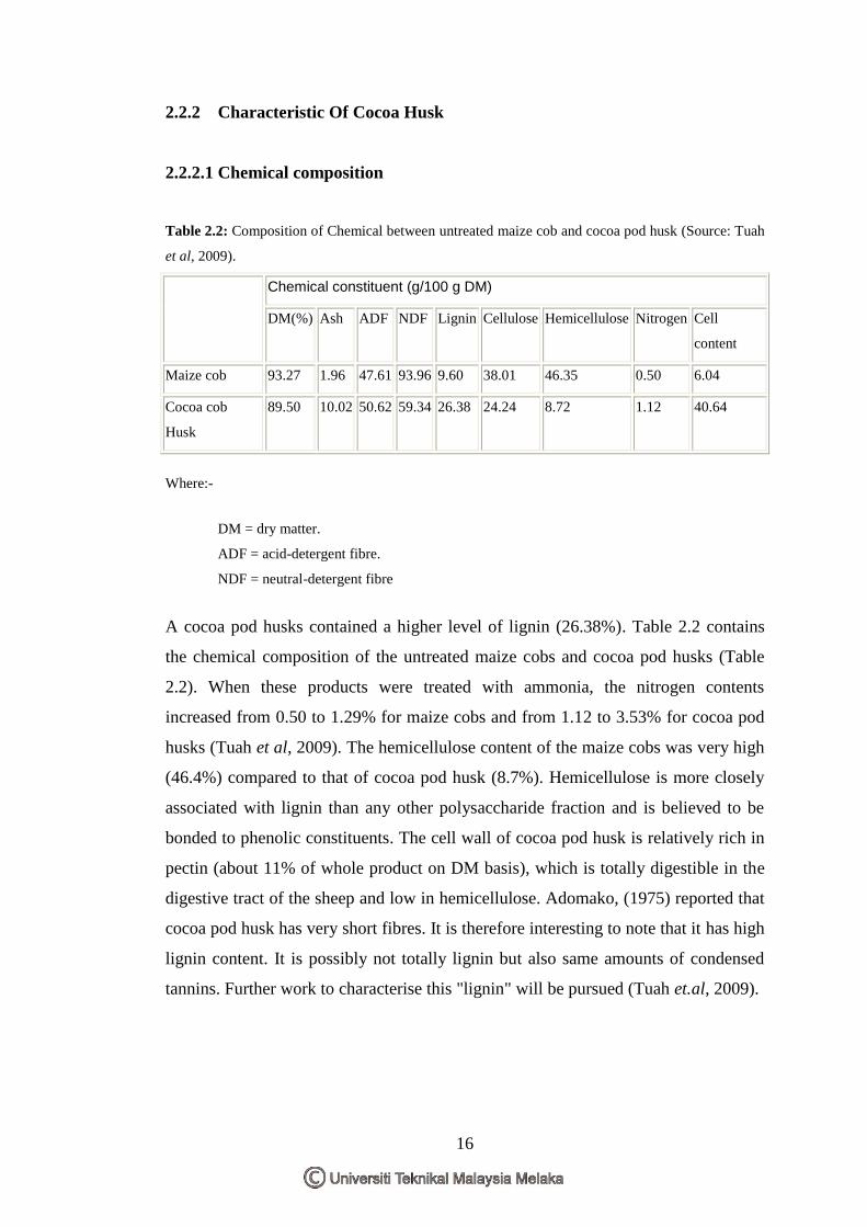
Table 2.2: Composition of Chemical between untreated maize cob and cocoa pod husk (Source: Tuah
et al, 2009).
Chemical constituent (g/100 g DM)
DM(%) Ash ADF NDF Lignin Cellulose Hemicellulose Nitrogen Cell
content
Maize cob 93.27 1.96 47.61 93.96 9.60 38.01 46.35 0.50 6.04
Cocoa cob
Husk
89.50 10.02 50.62 59.34 26.38 24.24 8.72 1.12 40.64
Where:-
DM = dry matter.
ADF = acid-detergent fibre.
NDF = neutral-detergent fibre
A cocoa pod husks contained a higher level of lignin (26.38%). Table 2.2 contains
the chemical composition of the untreated maize cobs and cocoa pod husks (Table
2.2). When these products were treated with ammonia, the nitrogen contents
increased from 0.50 to 1.29% for maize cobs and from 1.12 to 3.53% for cocoa pod
husks (Tuah et al, 2009). The hemicellulose content of the maize cobs was very high
(46.4%) compared to that of cocoa pod husk (8.7%). Hemicellulose is more closely
associated with lignin than any other polysaccharide fraction and is believed to be
bonded to phenolic constituents. The cell wall of cocoa pod husk is relatively rich in
pectin (about 11% of whole product on DM basis), which is totally digestible in the
digestive tract of the sheep and low in hemicellulose. Adomako, (1975) reported that
cocoa pod husk has very short fibres. It is therefore interesting to note that it has high
lignin content. It is possibly not totally lignin but also same amounts of condensed
tannins. Further work to characterise this "lignin" will be pursued (Tuah et.al, 2009).
17
2.2.2.2 Mechanical and Physical Of Cocoa Husk
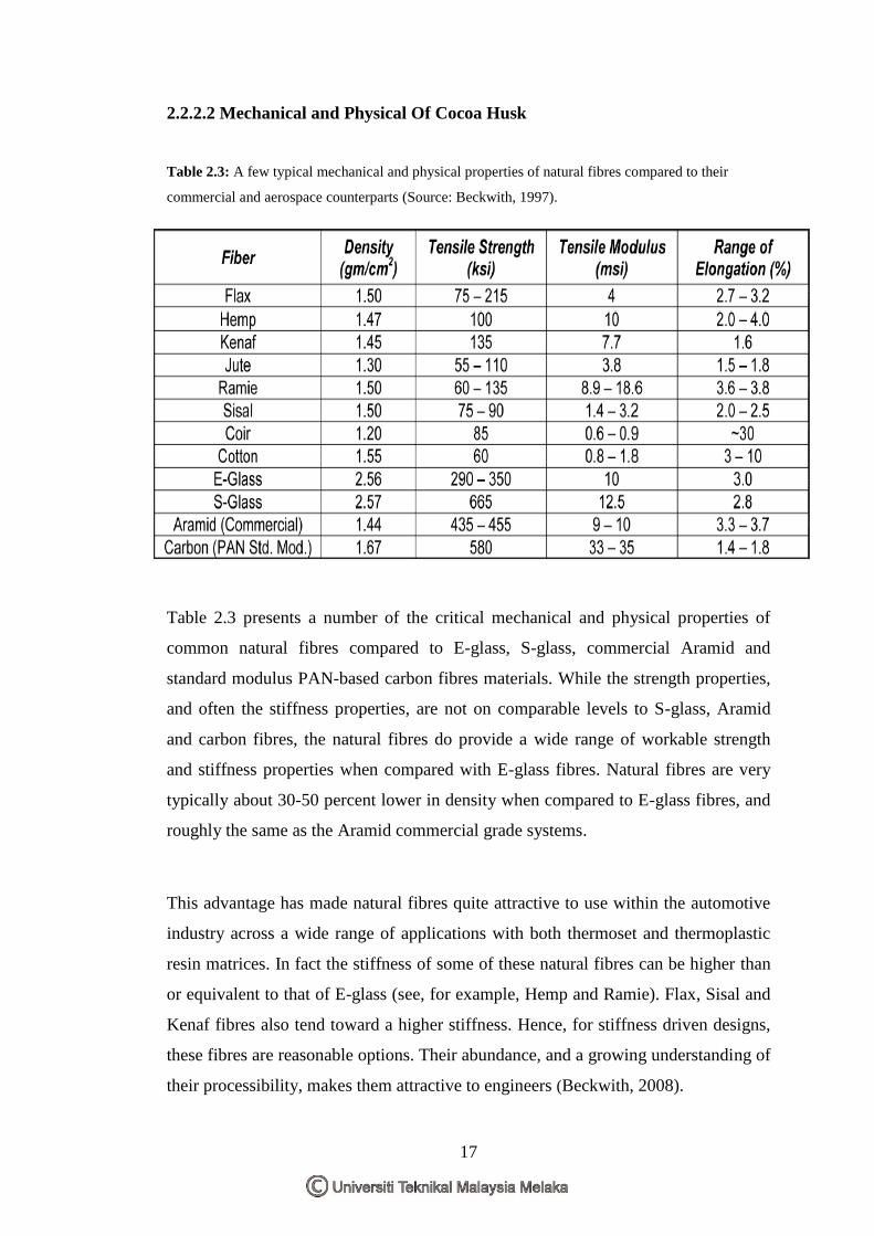
Table 2.3: A few typical mechanical and physical properties of natural fibres compared to their
commercial and aerospace counterparts (Source: Beckwith, 1997).
Table 2.3 presents a number of the critical mechanical and physical properties of
common natural fibres compared to E-glass, S-glass, commercial Aramid and
standard modulus PAN-based carbon fibres materials. While the strength properties,
and often the stiffness properties, are not on comparable levels to S-glass, Aramid
and carbon fibres, the natural fibres do provide a wide range of workable strength
and stiffness properties when compared with E-glass fibres. Natural fibres are very
typically about 30-50 percent lower in density when compared to E-glass fibres, and
roughly the same as the Aramid commercial grade systems.
This advantage has made natural fibres quite attractive to use within the automotive
industry across a wide range of applications with both thermoset and thermoplastic
resin matrices. In fact the stiffness of some of these natural fibres can be higher than
or equivalent to that of E-glass (see, for example, Hemp and Ramie). Flax, Sisal and
Kenaf fibres also tend toward a higher stiffness. Hence, for stiffness driven designs,
these fibres are reasonable options. Their abundance, and a growing understanding of
their processibility, makes them attractive to engineers (Beckwith, 2008).
18
2.3 Glass fibre
2.3.1 Introduction
Fiberglass or glass fibre is material made from extremely fine fibers of glass. It is
used as a reinforcing agent for many polymer products; the resulting composite
material, properly known as fiber-reinforced polymer (FRP) or glass-reinforced
plastic (GRP), is called "fiberglass" in popular usage. Glass fiber is formed when thin
strands of silica-based or other formulation glass is extruded into many fibers with
small diameters suitable for textile processing. Glass, even as a fiber, has little
crystalline structure.
The properties of the structure of glass in its softened stage are very much like its
properties when spun into fiber. One definition of glass is "an inorganic substance in
a condition which is continuous with, and analogous to the liquid state of that
substance, but which, as a result of a reversible change in viscosity during cooling,
has attained so high a degree of viscosity as to be for all practical purposes rigid"
(Anonymous 7, 2007).
In this research, E-glass is used as reinforcement in hybrid composite materials.
Commonly, E-glass is familiar use as the reinforcement material in polymer matrix
composites. Their properties such optimal strength is gained when straight,
continuous fibres are aligned parallel in a single direction. To promote strength in
other directions, laminate structures can be constructed, with continuous fibres
aligned in other directions.
2.3.2 Characteristic Of Glass fibre
Glass fibers are useful because of their high ratio of surface area to weight. However,
the increased surface area makes them much more susceptible to chemical attack. By
trapping air within them, blocks of glass fiber make good thermal insulation, with a
thermal conductivity on the order of 0.05 W/(mK).
Glass strengths are usually tested and reported for "virgin" fibers: those which have
just been manufactured. The freshest, thinnest fibers are the strongest because the
19
thinner fibers are more ductile. The more the surface is scratched, the less the
resulting tenacity. Because glass has an amorphous structure, its properties are the
same along the fiber and across the fiber. Humidity is an important factor in the
tensile strength. Moisture is easily adsorbed, and can worsen microscopic cracks and
surface defects, and lessen tenacity.
In contrast to carbon fiber, glass can undergo more elongation before it breaks. There
is a correlation between bending diameter of the filament and the filament diameter.
The viscosity of the molten glass is very important for manufacturing success.
During drawing (pulling of the glass to reduce fiber circumference) the viscosity
should be relatively low. If it is too high the fiber will break during drawing,
however if it is too low the glass will form droplets rather than drawing out into fiber
(Callister, 2003).
2.3.3 Composition of Glass fibre
Such structures are used in storage tanks and the likeS-Glass has a typical nominal
composition of SiO2 65wt%, Al2O3 25wt%, MgO 10wt%. E-Glass or electrical grade
glass was originally developed for stand off insulators for electrical wiring. It was
later found to have excellent fibre forming capabilities and is now used almost
exclusively as the reinforcing phase in the material commonly known as fibreglass.
E-Glass is a low alkali glass with a typical nominal composition of SiO2 54wt%,
Al2O3 14wt%, CaO+MgO 22wt%, B2O3 10wt% and Na2O+K2O less then 2wt%.
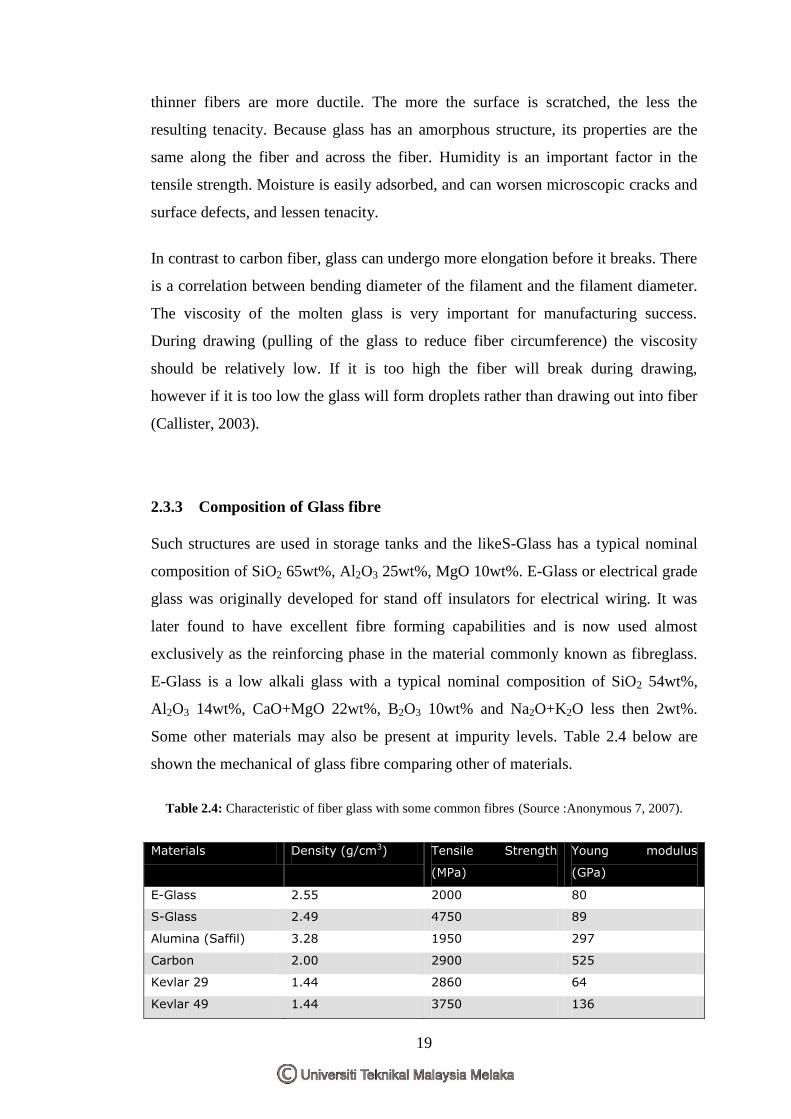
Some other materials may also be present at impurity levels. Table 2.4 below are
shown the mechanical of glass fibre comparing other of materials.
Table 2.4: Characteristic of fiber glass with some common fibres (Source :Anonymous 7, 2007).
Materials Density (g/cm3) Tensile Strength
(MPa)
Young modulus
(GPa)
E-Glass 2.55 2000 80
S-Glass 2.49 4750 89
Alumina (Saffil) 3.28 1950 297
Carbon 2.00 2900 525
Kevlar 29 1.44 2860 64
Kevlar 49 1.44 3750 136
20
2.4 Polypropylene (PP)
2.4.1 Introduction
Polypropylene (PP) is one of the most widely used plastics for packaging
applications. Polypropylene or polypropene (PP) is a thermoplastic polymer, made
by the chemical industry and used in a wide variety of applications, including food
packaging, ropes, textiles, stationary, plastic parts and reusable containers of various
types, laboratory equipment, loudspeakers, automotive components, and polymer
banknotes. In a continuously increasing part of this market, especially in the
pharmaceutical area, but also in food packaging and especially in medical
applications (syringes, pouches, tubes etc.), the material is sterilized in ore or the
other way.
The use of either heat (steam), radiation (β / electrons or γ) or chemicals (mostly
ethylene oxide) affects the mechanical and optical properties, but sometimes also the
organoleptics of the material significantly. From the literature it becomes clear that
the changes are quite different. Radiation, where mostly the effect of γ-rays has been
investigated in the past, induces chain scission and degradation effects, resulting in a
reduced melt viscosity and severe embrittlement. Parallel to that oxidized phenolic
antioxidants results in discoloration; the material becomes yellow.
2.4.2 Characteristic of Polypropylene
Polypropylene has an intermediate level of crystalline and Young‟s modulus between
that of low density polyethylene (LDPE) and high density polyethylene (HDPE).
However, Polypropylene has less tough than HDPE and less flexible than LDPE, it
much less brittle than HDPE. From this feature can make Polypropylene be used in
replacement for engineering plastic such as ABS. Polypropylene is rugged, stiffer
than some other plastics and reasonably economical. Polypropylene also can be made
translucent when uncoloured but not perfect as polystyrene, acrylic or certain other
plastics can be made. It can also be made opaque and sometime have many kinds of
colours. Polypropylene has excellent in resistance to fatigue, this reason allows most
21
plastic living hinges such as those on flip-top bottles are made from Polypropylene.
In certain high performance pulse and low loss RF capacitors, Polypropylene is used
as a dielectric in size very thin of sheets (Anonymous 8, 2009).
Again, also optical disturbances are possible in the form of significantly increased
haze of transparent articles. The post-sterilization changes are significant, but less
dramatic than in the irradiation case. While it is rather clear that chemical sterilizing
agents like ethylene oxide have a rather limited effect on PP, little experience exists
so far in public about modern alternative sterilization processes like electron (β)
irradiation, UV irradiation and the application of ozone.
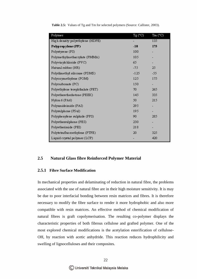
2.4.3 Mechanical and Physical of Polypropylene
All of these three methods are capable of forming radicals in the polymer, resulting
in similar degradation effects as the γ-radiation.In thermoplastic, polypropylene is
types of semi-crystalline structure.Semi-crystalline materials such as polyamides do
not exhibit a clear Tg or 'rubbery' region, although one is often quoted as the
amorphous parts of the structure will undergo some transition. Some chain rotation in
the amorphous regions will occur below Tm, giving some impact resistance at these
temperatures. Values of Tg and Tm for a number of polymers are given in Table 2.5.
From the table below is shown the Tg and Tm for Polypropylene is -10OC and 176
OC
(Callister, 2003).
22
Table 2.5: Values of Tg and Tm for selected polymers (Source: Callister, 2003).
2.5 Natural Glass fibre Reinforced Polymer Material
2.5.1 Fibre Surface Modification
In mechanical properties and delaminating of reduction in natural fibre, the problems
associated with the use of natural fibre are in their high moisture sensitivity. It is may
be due to poor interfacial bonding between resin matrices and fibres. It is therefore
necessary to modify the fibre surface to render it more hydrophobic and also more
compatible with resin matrices. An effective method of chemical modification of
natural fibres is graft copolymerisation. The resulting co-polymer displays the
characteristic properties of both fibrous cellulose and grafted polymer. One of the
most explored chemical modifications is the acetylation esterification of cellulose-
OH, by reaction with acetic anhydride. This reaction reduces hydrophilicity and
swelling of lignocelluloses and their composites.
23
The effect by using sodium- alginate and sodium hydroxide as a chemical treatment
for natural fibre such as coir, banana, and sisal fibre has been increase in adhesion
bonding and thus improve ultimate tensile strength up to 30% .According to
researcher, Saira et al, 2007 have reported that treatment of jute with
polycondensates such as phenol-formaldehyde, melamine-formaldehyde and cashew
nut shell with liquid-formaldehyde improves the wetability of jute fibres and reduces
water regain properties. The chemical modification of pineapple leaf fibres using
alkali treatment, diazo coupling with aniline and cross-linking with formaldehyde.
These chemical treatments result in signified cant improvements in mechanical
properties; chemical resistance and reduced moisture regain. Finally, the influence of
chemical treatment with sodium hydroxide, isocyanate and peroxide on the
properties of sisal/polyethylene composites has investigated by Saira et al, 2007.
The observed enhancement in properties of the composites and attributed to this the
strong bonding between sisal and polyethylene matrix. In an effort to improve the
mechanical properties of recycled HDPE/wood fibre composites, the use of several
additives with possible effect on the fibre/matrix adhesion or fibre dispersion into the
matrix has been found that malefic anhydride modified polypropylene appears
especially promising, since its use at a concentration of 5% in composites with 30%
wood fibre results in an increase in tensile strength and elongation at break ( Saira et
al,2007).
Similar results have been obtained by Dalvag et.al, 1985, who has reported that the
composite‟s elastic modulus remains unchanged. Some coupling agents, namely
trichloro-striazineand di-methylol melamine can produce covalent bonds between
celluloses materials and polymer matrices, leading to modified performance and
reduced sensitivity to water. This approach has been further explored by Maldas and
Kokta , who used phthalic anhydride as coupling agent for wood fibre/polystyrene
composites. In addition to the chemical affinity of the benzene rings of phthalic
anhydride with those of polystyrene, the anhydride group can directly attack the OH
group of cellulose. Furthermore, Razi et.al,1999) found that the treatment of wood
with sodium hydroxide followed by drying with vinyltrimethoxysilance is superior,
for obtaining maximum bonding strength at the wood/polymer interface that yields
improved mechanical properties (Saira et al, 2007).
24
2.5.2 Coupling Agent Addition
Many other coupling agents have also been investigated, namely anhydrides,
maleated polymer, isocyanates, and alkoxysilances. Among these different reagents,
maleated polypropylene (MaPP) or polyethylene (MaPE) gives signifies cant
enhancement in tensile and flexural strength, ranging from 40 up to 80%, when they
are blended with cellulose fibres before mixing with matrix ( Saira et al, 2007).
Silane chemical coupling presents three main advantages:
a) They are commercially available in large scale,
b) At one end, they bear alkoxysilane groups capable of reacting with OH-rich
surface, and
c) At the second end, they have a large number of functional groups which can
be tailored as a function of the matrix to be used.
The last feature ensures, at least, a good compatibility between the reinforcing
element and the polymer matrix or even covalent bonds between them. The reaction
of silane coupling agents with lignocelluloses fibres (mainly: cellulose and lignin)
has been found to be quite different in comparison with that observed between them
and glass surface, in the sense that with cellulose macromolecules, only
prehydrolyzed silanes undergo the reaction with cellulose surface . Besides the
chemical bonding theory, other theories such as the interpenetrating networks theory
have also been proposed. This theory states that the matrix diffuses inside the silane
interphase to form an entangled network. A number of attempts have been carried
out to understand the silane-cellulose system. Thus, the interaction of silane coupling
agents with cellulosic fibres and the effect of some parameters, such as pH, the initial
amount of silane with respect to cellulose and the adsorption contact time, on their
anchoring capability onto the fibre surface have been ascertained ( Saira et al, 2007).
25
2.6 Mechanical Properties
2.6.1 Introduction
Mechanical responses of this type of composite depend on several factors to include
the stress-strain behaviors of fibre and matrix phases, the phase volume fractions,
and in addition, the direction in which the stress or load is applied. Furthermore, the
properties of a composite having its fibres aligned are highly anisotropic, that is
dependent on the direction in which they are measured. The mechanical
characteristic of a fibre-reinforced composite depend not only on the properties of
the fibre, but also on the degree to which an applied load is transmitted to the fibres
by the matrix phase. Under an applied stress, this fibre matrix bond ceases at the
fibre ends, yielding a matrix deformation pattern. Some critical fibre length is
necessary for effective strengthening and stiffening of the composite materials.
2.6.2 Tensile Strength
The ability of a material to resist breaking under tensile stress is one of the most
important and widely measured properties of materials used in structural
applications. The force per unit area (MPa or psi) required to break a material in such
a manner is the ultimate tensile strength or tensile strength at break. The rate at
which a sample is pulled apart in the test can range from 0.2 to 20 inches per minute
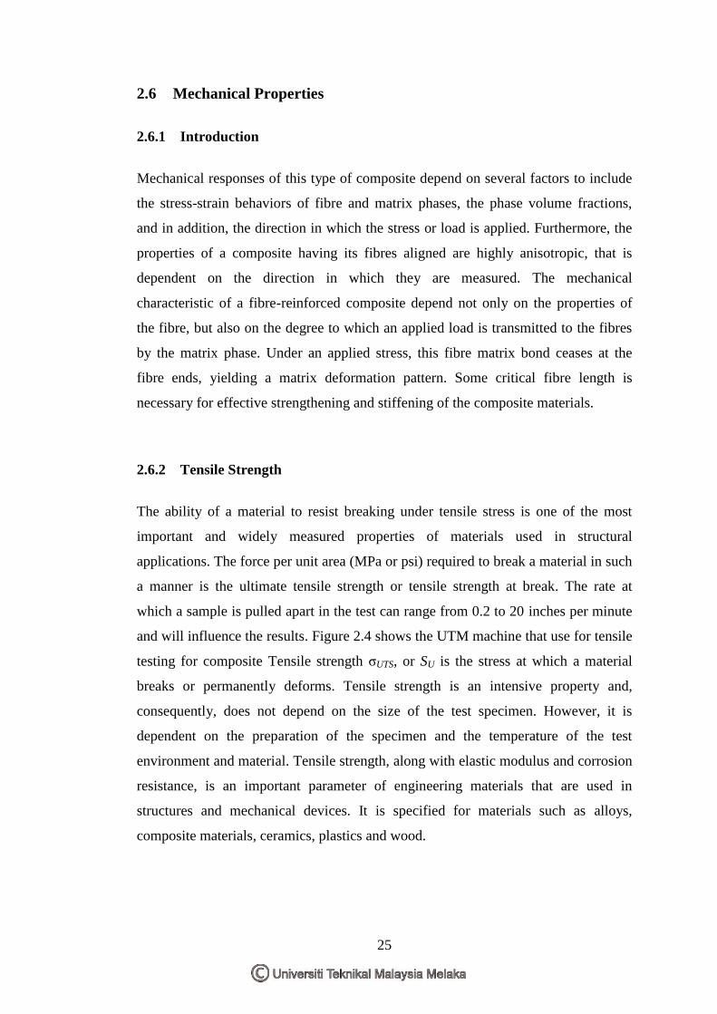
and will influence the results. Figure 2.4 shows the UTM machine that use for tensile
testing for composite Tensile strength σUTS, or SU is the stress at which a material
breaks or permanently deforms. Tensile strength is an intensive property and,
consequently, does not depend on the size of the test specimen. However, it is
dependent on the preparation of the specimen and the temperature of the test
environment and material. Tensile strength, along with elastic modulus and corrosion
resistance, is an important parameter of engineering materials that are used in
structures and mechanical devices. It is specified for materials such as alloys,
composite materials, ceramics, plastics and wood.
26
Figure 2.4: Tensile Testing
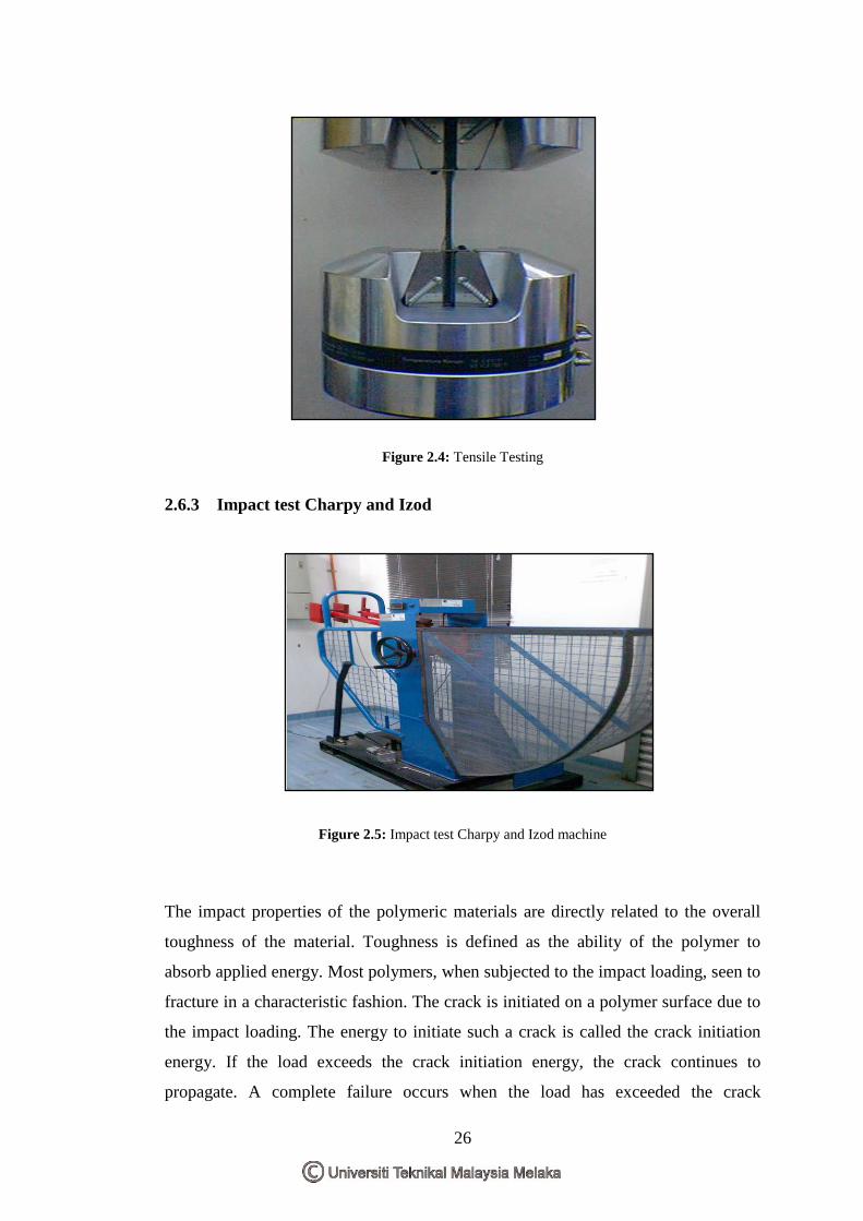
2.6.3 Impact test Charpy and Izod
Figure 2.5: Impact test Charpy and Izod machine
The impact properties of the polymeric materials are directly related to the overall
toughness of the material. Toughness is defined as the ability of the polymer to
absorb applied energy. Most polymers, when subjected to the impact loading, seen to
fracture in a characteristic fashion. The crack is initiated on a polymer surface due to
the impact loading. The energy to initiate such a crack is called the crack initiation
energy. If the load exceeds the crack initiation energy, the crack continues to
propagate. A complete failure occurs when the load has exceeded the crack
27
propagation energy. Thus, both crack initiation and crack propagation contribute to
the measured impact energy. Impact testing is divided by two method; Charpy test
and Izod test. The Charpy impact test, also known as the Charpy v-notch test, is a
standardized high strain-rate test which determines the amount of energy absorbed by
a material during fracture. This absorbed energy is a measure of a given material's
toughness and acts as a tool to study temperature-dependent brittle-ductile transition.
It is widely applied in industry, since it is easy to prepare and conduct and results can
be obtained quickly and cheaply. But a major disadvantage is that all results are only
comparative. Notched Izod Impact is a single point test that measures a materials
resistance to impact from a swinging pendulum. Izod impact is defined as the kinetic
energy needed to initiate fracture and continue the fracture until the specimen is
broken. Izod specimens are notched to prevent deformation of the specimen upon
impact. This test can be used as a quick and easy quality control check to determine
if a material meets specific impact properties or to compare materials for general
toughness (Anonymous 9, 2007).
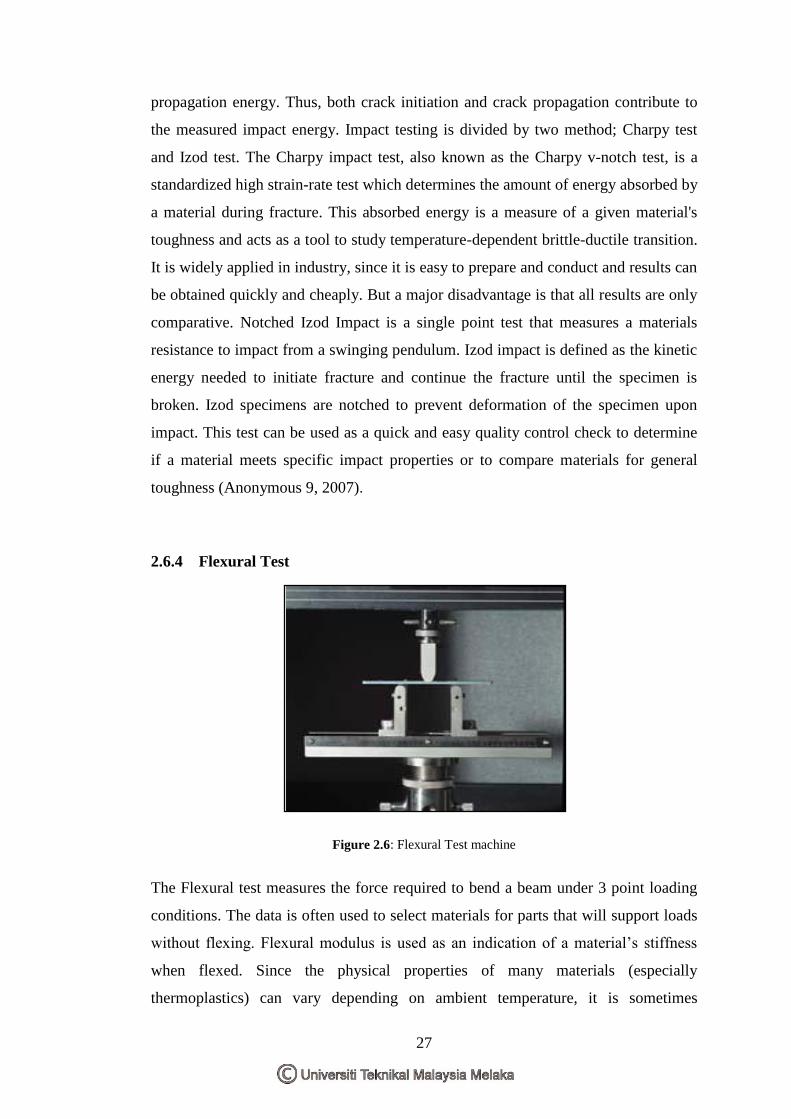
2.6.4 Flexural Test
Figure 2.6: Flexural Test machine
The Flexural test measures the force required to bend a beam under 3 point loading
conditions. The data is often used to select materials for parts that will support loads
without flexing. Flexural modulus is used as an indication of a material‟s stiffness
when flexed. Since the physical properties of many materials (especially
thermoplastics) can vary depending on ambient temperature, it is sometimes
28
appropriate to test materials at temperatures that simulate the intended end use
environment.The three points bending flexural test provides values for the modulus
of elasticity in bending EB, flexural stress σf, flexural strain εf and the flexural stress-
strain response of the material. The main advantage of a three point flexural test is
the ease of the specimen preparation and testing. However, this method has also
some disadvantages: the results of the testing method are sensitive to specimen and
loading geometry and strain rate.
In engineering mechanics, bending (also known as flexure) characterizes the
behavior of a structural element subjected to an external load applied perpendicular
to the axis of the element. A structural element subjected to bending is known as a
beam. A closet rod sagging under the weight of clothes on clothes hangers is an
example of a beam experiencing bending (Anonymous 10, 2007).
2.7 Physical Properties of Composite
2.7.1 Water Absorption Properties
All polymer composites absorb moisture in humid atmosphere and when immersed
in water. The effect of absorption of moisture leads to the degradation of fibre matrix
interface region to creating poor stress transfer efficiencies resulting in a reduction of
mechanical and dimensional properties. One of the main concerns for the use of
natural fibre reinforced composite materials is their susceptibility to moisture
absorption and the effect on physical, mechanical and thermal properties. It is
important therefore that this problem is addressed in order that natural fibre may be
considered as a viable reinforcement in composite materials. Several studies in the
use of natural fibre reinforced polymeric composites have shown that the sensitivity
of certain mechanical and thermal properties to moisture uptake can be reduced by
the use of coupling agents and fibre surface treatments. Moisture diffusion in
polymeric composites has shown to be governed by three different mechanisms. The
first involves of diffusion of water molecules inside the micro gaps between polymer
chains. The second involves capillary transport into the gaps and flaws at the
interfaces between fibre and the matrix. This is a result of poor wetting and
29
impregnation during the initial manufacturing stage. The third involves transport of
microcracks in the matrix arising from the swelling of fibres (particularly in the case
of natural fibre composites). Generally, based on these mechanisms, diffusion
behavior of polymeric composites can further be classified according to the relative
mobility of the penetrate and of the polymer segments, which is related to either
Fickian, non-Fickian or anomalous, and an intermediate behavior between Fickian
and non-Fickian . In general moisture diffusion in a composite depends on factors
such as volume fraction of fibre, voids, viscosity of matrix, humidity and temperature
(Saira et al, 2007).
2.8 Morphology Properties of Composite
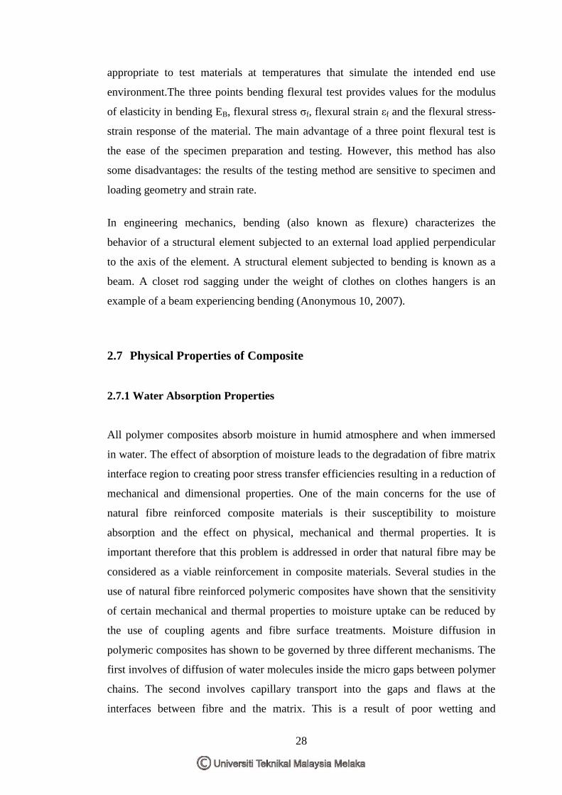
2.8.1 Morphology of Fibre
Figure 2.7 (a) has been taken of unmodified (standard) coir with modified coir fibers,
hardly any difference in the surface structure between the fibers can be observed at
low magnification (magnification factor 3250). The coir fibers display many pinholes
on the surface („rotten wood‟-like appearance). The diameters of natural fibers (coir
as well as sisal) vary considerably. The SEM micrograph of untreated (standard) coir
Figure 2.7 (a) clearly demonstrates the presence of longitudinally orientated unit
cells with more or less parallel orientations. The intercellular space is filled up by the
binder lignin and fatty substances, which hold the unit cells firmly in a fibre
(Bismarck et al, 2001).
30
Figure 2.7: Standard Coir (Source: Bismarck et al, 2001).
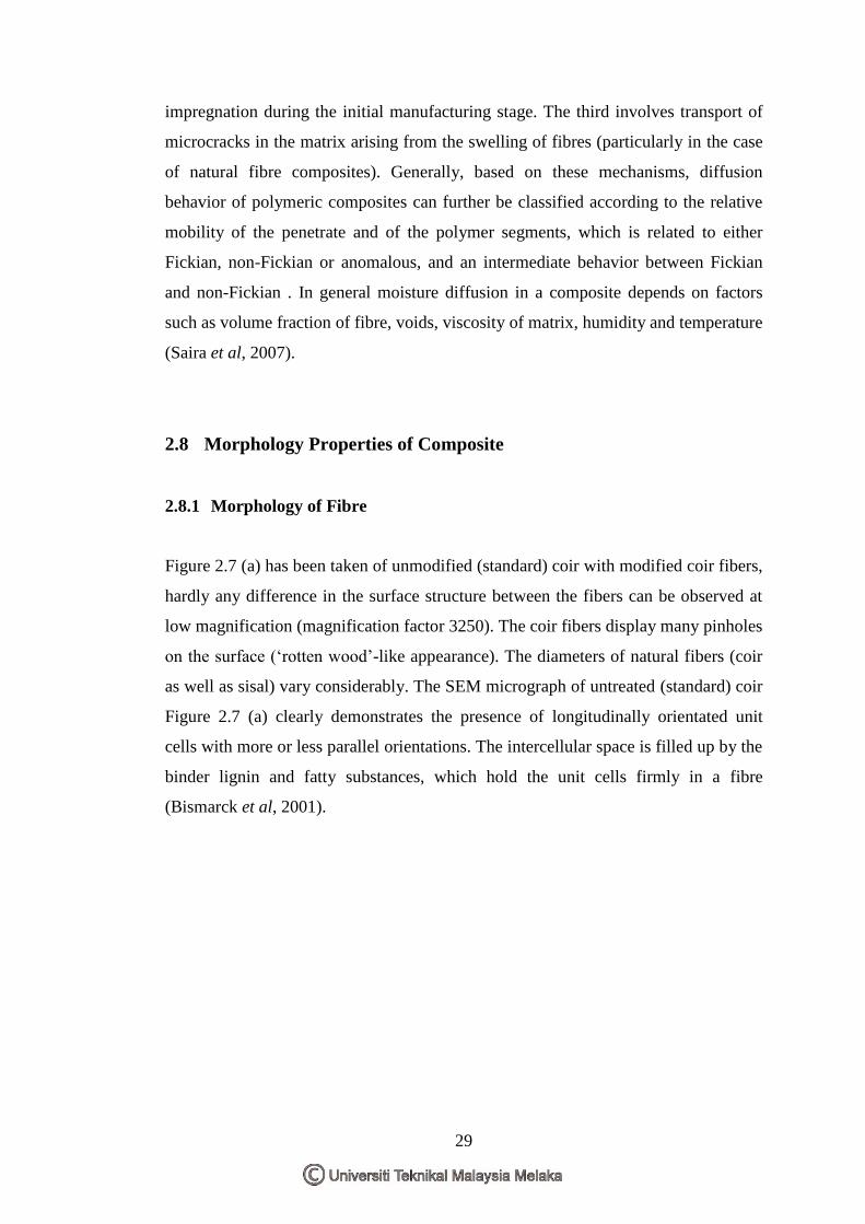
2.8.2 Morphology of Effect of the Fiber Loading On the Composite
Examination of the fracture surfaces of the composites by scanning electron
microscope gave information about how impact modifiers and MAPP affect the
morphology of the composite. The rubber particle sizes and the interracial region
between the PP matrix and the wood filler were investigated. Figure 2.8 shows the
microstructure of the composite without impact modifier and compatibilizer (blend
1) showing a wood particle embedded in the polymer matrix. The wood particle is
not broken and there are voids around the particle indicating poor interaction
between the wood surface and the PP matrix. The WF particles were well dispersed
on the PP matrix (Bismarck et al, 2001).
31
Figure 2.8: SEM micrograph of room temperature fractured specimen. Interface/ interphase region
between the wood filler and the PP matrix (Source: Bismarck et al, 2001).
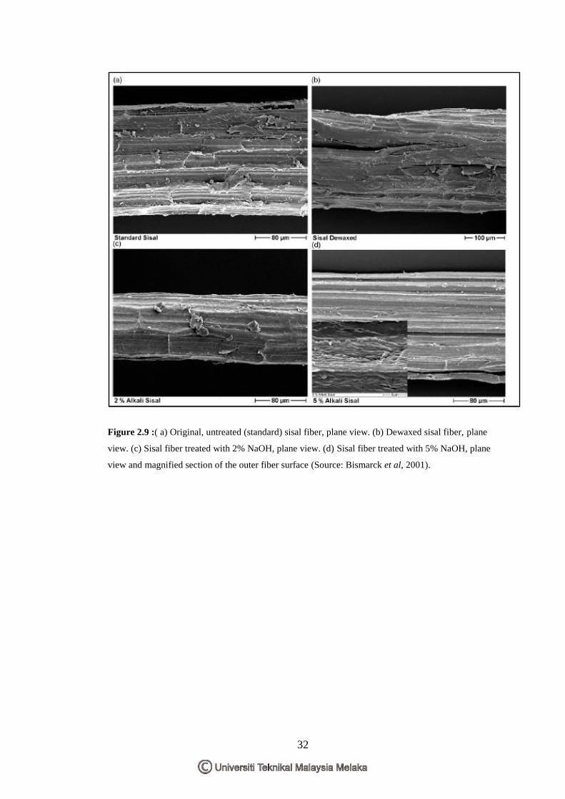
2.8.3 Morphology of Surface Fracture of the Composite
Comparing the coir fibers with sisal fibers (Figure 2.9 (a)–(d), magnification factor
3400) it is seen that coir fibers are much larger in diameter and they look smoother.
Again only the unmodified sisal fiber (Figure 2.9 (a)) seems to be a little bit rougher
compared to the surface modified sisal fibers (Figure 2.9 (b)–(d)) containing small
particles (possibly waxes and fats) attached to the fiber surface. These particles thus
appear to be removed by the applied modification procedures (dewaxing, treatment
with NaOH). All sisal fibers display a grain-like surface structure (Bismarck et al,
2001).
\
32
Figure 2.9 :( a) Original, untreated (standard) sisal fiber, plane view. (b) Dewaxed sisal fiber, plane
view. (c) Sisal fiber treated with 2% NaOH, plane view. (d) Sisal fiber treated with 5% NaOH, plane
view and magnified section of the outer fiber surface (Source: Bismarck et al, 2001).
33
CHAPTER 3
MATERIALS & METHODOLOGY
3.1 Materials
3.1.1 Introduction
In this research, the hybrid composite method is used in several materials as a matrix
and reinforcement to get new properties of composite. Natural fibre such as cocoa
pod husk is the main of this research following by fibre glass (E-glass) as filler and
Polyproplylene as matrix.
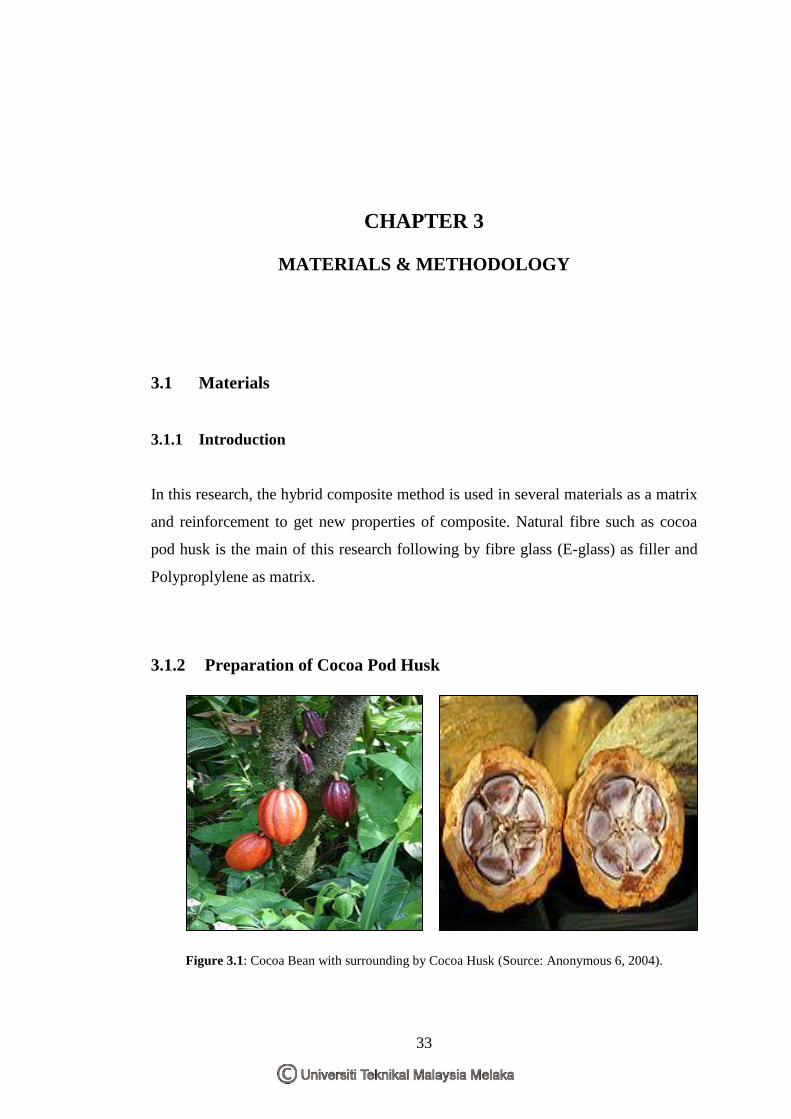
3.1.2 Preparation of Cocoa Pod Husk
Figure 3.1: Cocoa Bean with surrounding by Cocoa Husk (Source: Anonymous 6, 2004).
34
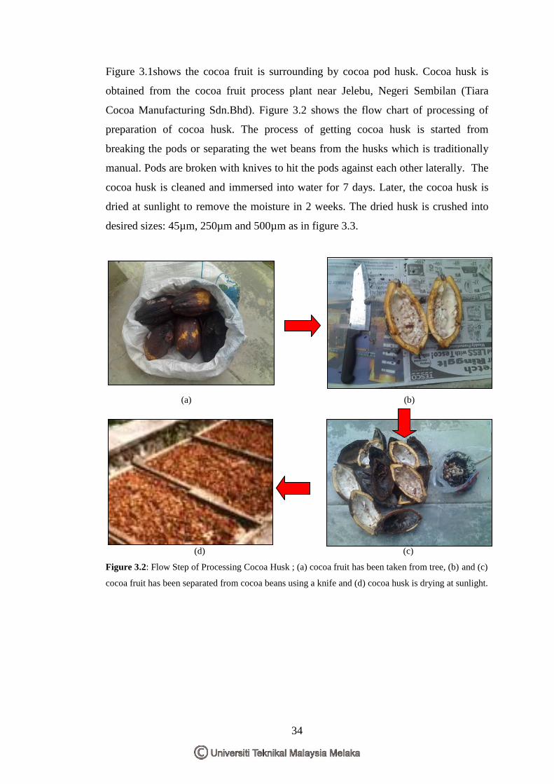
Figure 3.1shows the cocoa fruit is surrounding by cocoa pod husk. Cocoa husk is
obtained from the cocoa fruit process plant near Jelebu, Negeri Sembilan (Tiara
Cocoa Manufacturing Sdn.Bhd). Figure 3.2 shows the flow chart of processing of
preparation of cocoa husk. The process of getting cocoa husk is started from
breaking the pods or separating the wet beans from the husks which is traditionally
manual. Pods are broken with knives to hit the pods against each other laterally. The
cocoa husk is cleaned and immersed into water for 7 days. Later, the cocoa husk is
dried at sunlight to remove the moisture in 2 weeks. The dried husk is crushed into
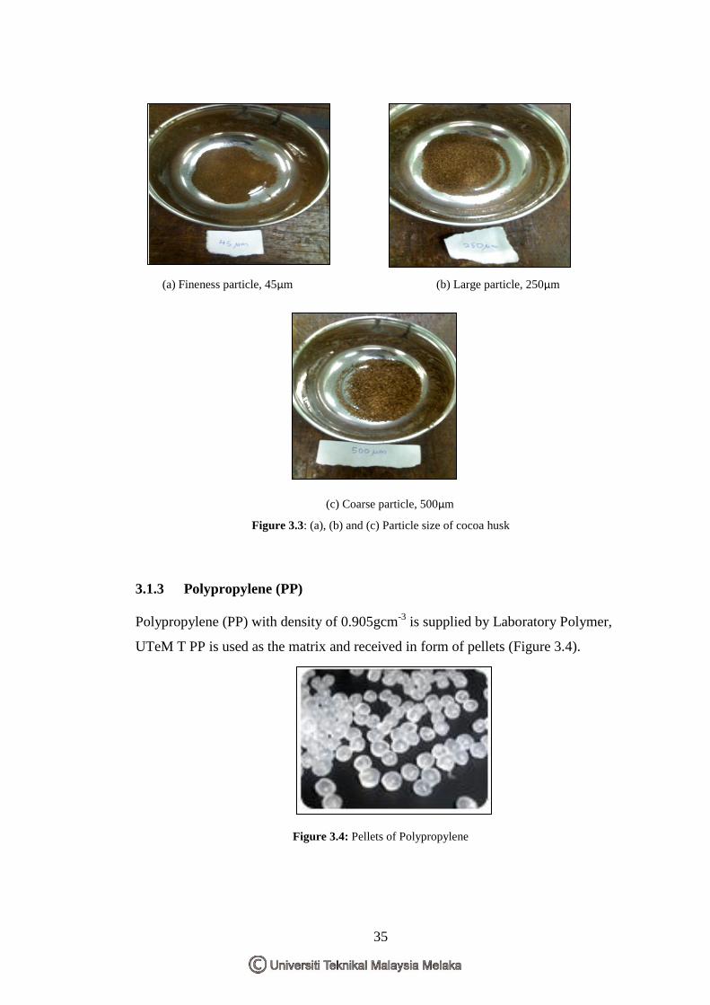
desired sizes: 45µm, 250µm and 500µm as in figure 3.3.
(a) (b)
(d) (c)
Figure 3.2: Flow Step of Processing Cocoa Husk ; (a) cocoa fruit has been taken from tree, (b) and (c)
cocoa fruit has been separated from cocoa beans using a knife and (d) cocoa husk is drying at sunlight.
35
(a) Fineness particle, 45µm (b) Large particle, 250µm
(c) Coarse particle, 500µm
Figure 3.3: (a), (b) and (c) Particle size of cocoa husk
3.1.3 Polypropylene (PP)
Polypropylene (PP) with density of 0.905gcm-3
is supplied by Laboratory Polymer,
UTeM T PP is used as the matrix and received in form of pellets (Figure 3.4).
Figure 3.4: Pellets of Polypropylene
36
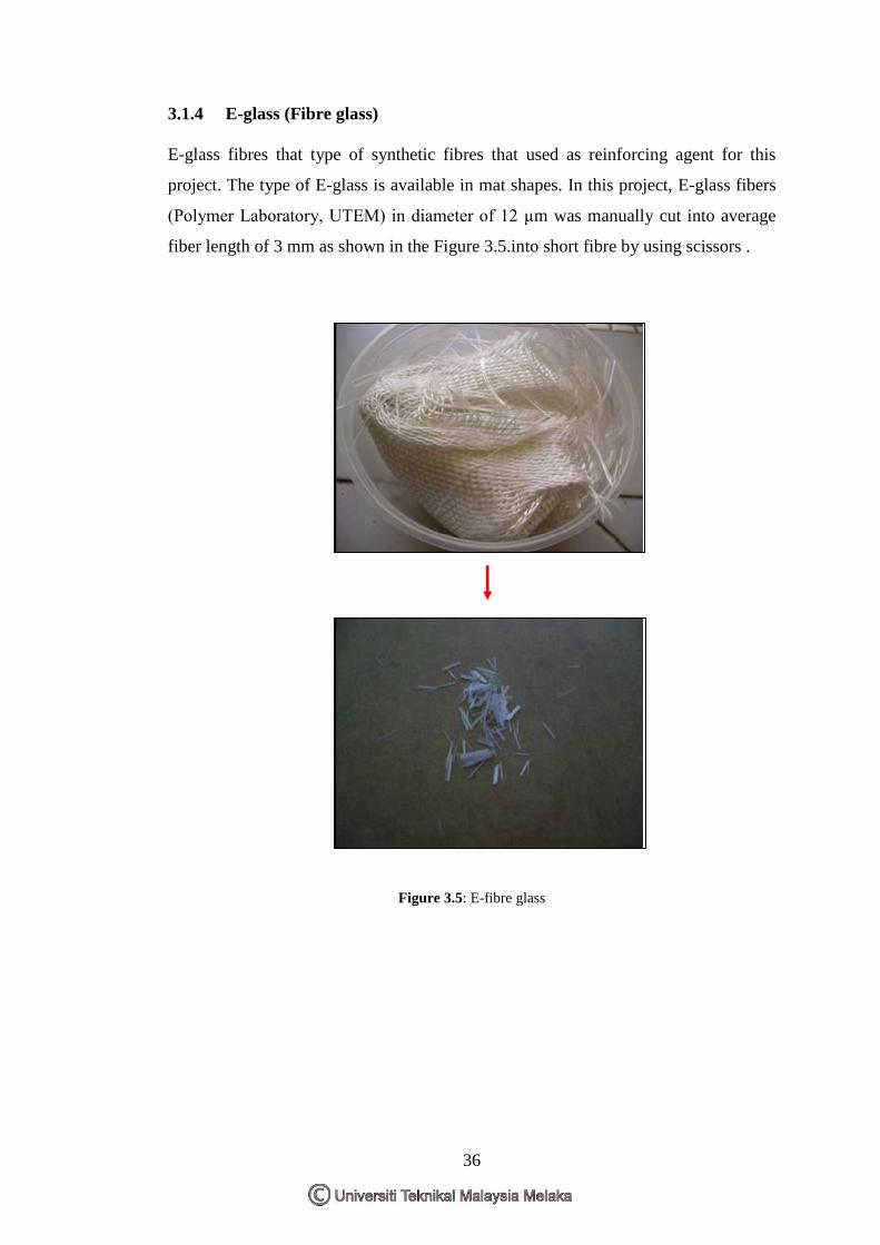
3.1.4 E-glass (Fibre glass)
E-glass fibres that type of synthetic fibres that used as reinforcing agent for this
project. The type of E-glass is available in mat shapes. In this project, E-glass fibers
(Polymer Laboratory, UTEM) in diameter of 12 μm was manually cut into average
fiber length of 3 mm as shown in the Figure 3.5.into short fibre by using scissors .
Figure 3.5: E-fibre glass
37
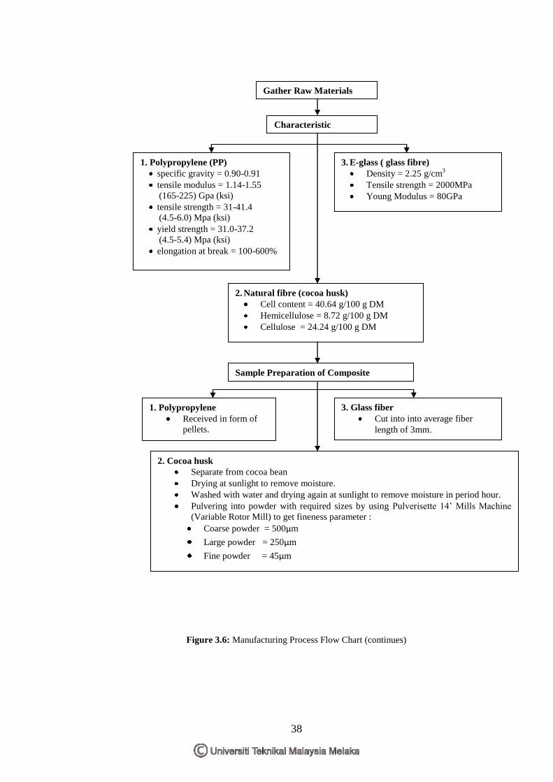
3.2 Methodology
3.2.1 Introduction
The preparation of raw materials has been done on the cocoa husk and E-glass fiber.
The cocoa fiber was dried in oven (Universal Ovens, UNB 100-500) for 24 h at
105 C to a moisture content of 1-2 % (based on dry weight) before processing. Then,
the cocoa fiber is crushed and into powder with different range of sizes; 45µm,
250µm and 500µm. The E-glass fiber length was manually cut into average fiber
length of 3mm. Plastic granulates; polypropylene, cocoa fiber and E-glass fiber was
compounded using a co-rotating twin-screw extruder (Polylab Extruder, HAAKE
Rheomix OS). The temperatures were between 180°C and 200 °C. The screw speed
set at 50 rpm. Finally the mixed samples coming out in bulk form. The crushing
machine is used to crush in particle form. The compound of hybrid composite is
fabricated in 300mm x 300mm x 30mm of dimension of mold. The melting point is
200°C with pressure of 25 Ton for 10 min and the timer for hot is10minutes and cold
is 15minutes. Each of plate are cut into desired dimension for specimens testing The
first testing was tensile test, followed by flexural test, impact test and finally the
water absorption. And the last study made was the microstructure observation using
the Scanning Electron Microscope (SEM). The schematic of the methodology
process flow of the project can be review at Figure 3.6.
38
Figure 3.6: Manufacturing Process Flow Chart (continues)
Gather Raw Materials
2. Natural fibre (cocoa husk)
Cell content = 40.64 g/100 g DM
Hemicellulose = 8.72 g/100 g DM
Cellulose = 24.24 g/100 g DM
3. E-glass ( glass fibre)
Density = 2.25 g/cm3
Tensile strength = 2000MPa
Young Modulus = 80GPa
1. Polypropylene (PP)
specific gravity = 0.90-0.91
tensile modulus = 1.14-1.55
(165-225) Gpa (ksi)
tensile strength = 31-41.4
(4.5-6.0) Mpa (ksi)
yield strength = 31.0-37.2
(4.5-5.4) Mpa (ksi)
elongation at break = 100-600%
Sample Preparation of Composite
2. Cocoa husk
Separate from cocoa bean
Drying at sunlight to remove moisture.
Washed with water and drying again at sunlight to remove moisture in period hour.
Pulvering into powder with required sizes by using Pulverisette 14‟ Mills Machine
(Variable Rotor Mill) to get fineness parameter :
Coarse powder = 500µm
Large powder = 250µm
Fine powder = 45µm
3. Glass fiber
Cut into into average fiber
length of 3mm.
1. Polypropylene
Received in form of
pellets.
Characteristic
39
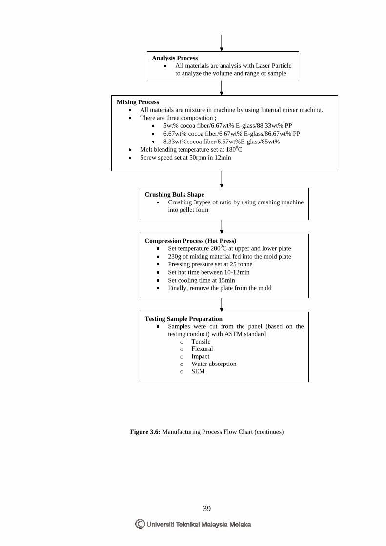
Figure 3.6: Manufacturing Process Flow Chart (continues)
Analysis Process
All materials are analysis with Laser Particle
to analyze the volume and range of sample
Mixing Process
All materials are mixture in machine by using Internal mixer machine.
There are three composition ;
5wt% cocoa fiber/6.67wt% E-glass/88.33wt% PP
6.67wt% cocoa fiber/6.67wt% E-glass/86.67wt% PP
8.33wt%cocoa fiber/6.67wt%E-glass/85wt%
Melt blending temperature set at 1800C
Screw speed set at 50rpm in 12min
Crushing Bulk Shape
Crushing 3types of ratio by using crushing machine
into pellet form
Compression Process (Hot Press)
Set temperature 2000C at upper and lower plate
230g of mixing material fed into the mold plate
Pressing pressure set at 25 tonne
Set hot time between 10-12min
Set cooling time at 15min
Finally, remove the plate from the mold
Testing Sample Preparation
Samples were cut from the panel (based on the
testing conduct) with ASTM standard
o Tensile
o Flexural
o Impact
o Water absorption
o SEM
40
Figure 3.6: Manufacturing Process Flow Chart
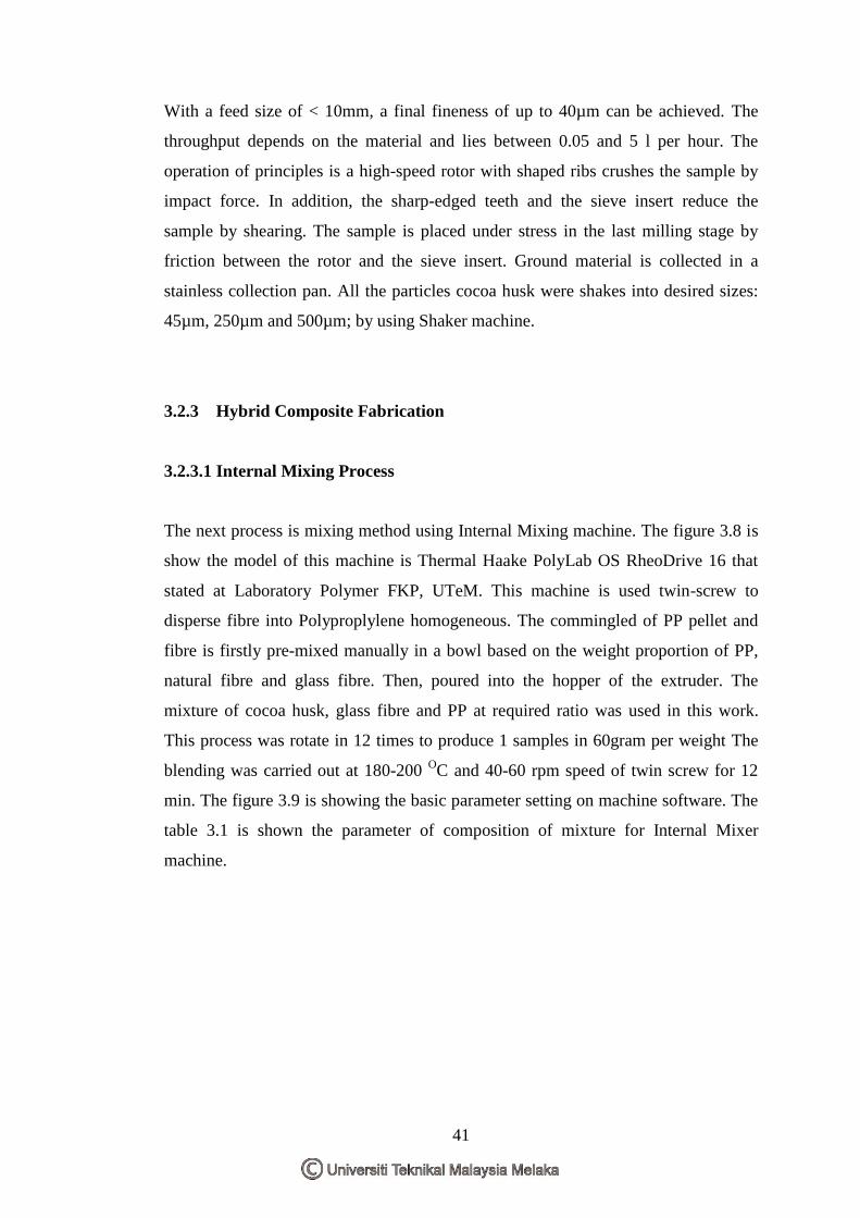
3.2.2 Raw materials Preparation
Pulverizing process has been done on the cocoa husk that dried. There were sieved
using Variables Speed Rotor Mill at 300μm to 500μm aperture sizes based on the
optimum tensile results (Anuar et.al, 2005). Figure 3.7 shows the Variables Speed
Rotor Mill that was used is the Pulverisette 14 from FRITSCH which is available in
Laboratory Material FKP. The machine is run between 12 to 14 rpm depend on the
size of cocoa pod husk the run time is set for 3 minutes to prevent the machine from
overheated.
Figure 3.7: Pulverisette 14 with 12-ribs-rotor and Sieve Ring (Source; Fritsch GmbH)
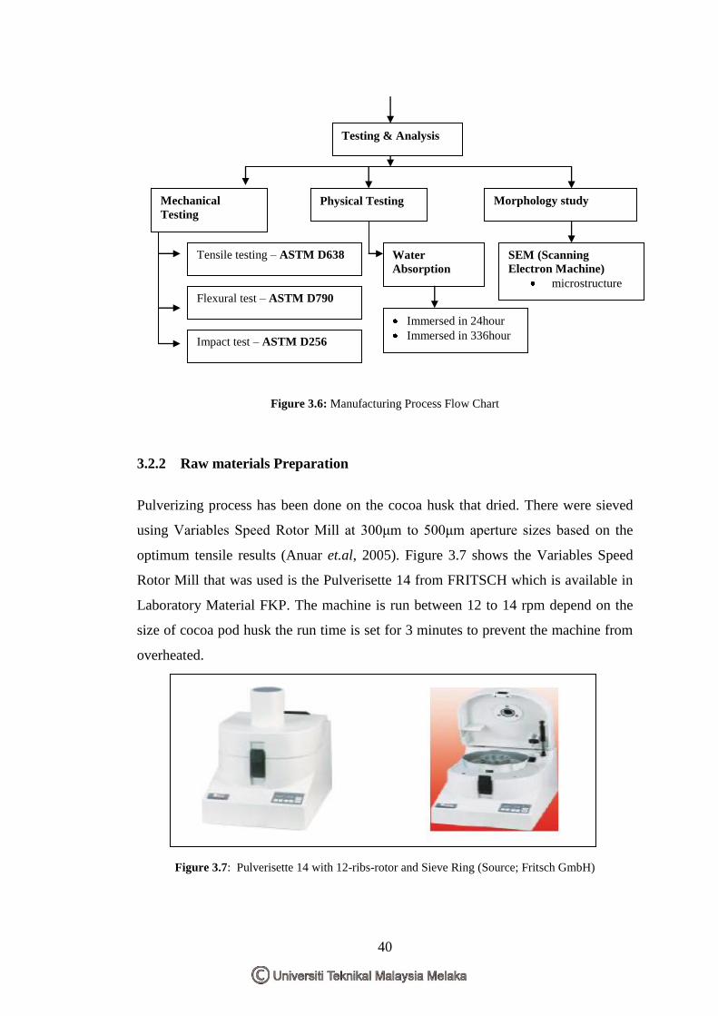
Testing & Analysis
Morphology study
Mechanical
Testing
Tensile testing – ASTM D638
Flexural test – ASTM D790
Impact test – ASTM D256
Physical Testing
SEM (Scanning
Electron Machine)
microstructure
Immersed in 24hour
Immersed in 336hour
Water
Absorption
41
With a feed size of < 10mm, a final fineness of up to 40µm can be achieved. The
throughput depends on the material and lies between 0.05 and 5 l per hour. The
operation of principles is a high-speed rotor with shaped ribs crushes the sample by
impact force. In addition, the sharp-edged teeth and the sieve insert reduce the
sample by shearing. The sample is placed under stress in the last milling stage by
friction between the rotor and the sieve insert. Ground material is collected in a
stainless collection pan. All the particles cocoa husk were shakes into desired sizes:
45µm, 250µm and 500µm; by using Shaker machine.
3.2.3 Hybrid Composite Fabrication
3.2.3.1 Internal Mixing Process
The next process is mixing method using Internal Mixing machine. The figure 3.8 is
show the model of this machine is Thermal Haake PolyLab OS RheoDrive 16 that
stated at Laboratory Polymer FKP, UTeM. This machine is used twin-screw to
disperse fibre into Polyproplylene homogeneous. The commingled of PP pellet and
fibre is firstly pre-mixed manually in a bowl based on the weight proportion of PP,
natural fibre and glass fibre. Then, poured into the hopper of the extruder. The
mixture of cocoa husk, glass fibre and PP at required ratio was used in this work.
This process was rotate in 12 times to produce 1 samples in 60gram per weight The
blending was carried out at 180-200 OC and 40-60 rpm speed of twin screw for 12
min. The figure 3.9 is showing the basic parameter setting on machine software. The
table 3.1 is shown the parameter of composition of mixture for Internal Mixer
machine.
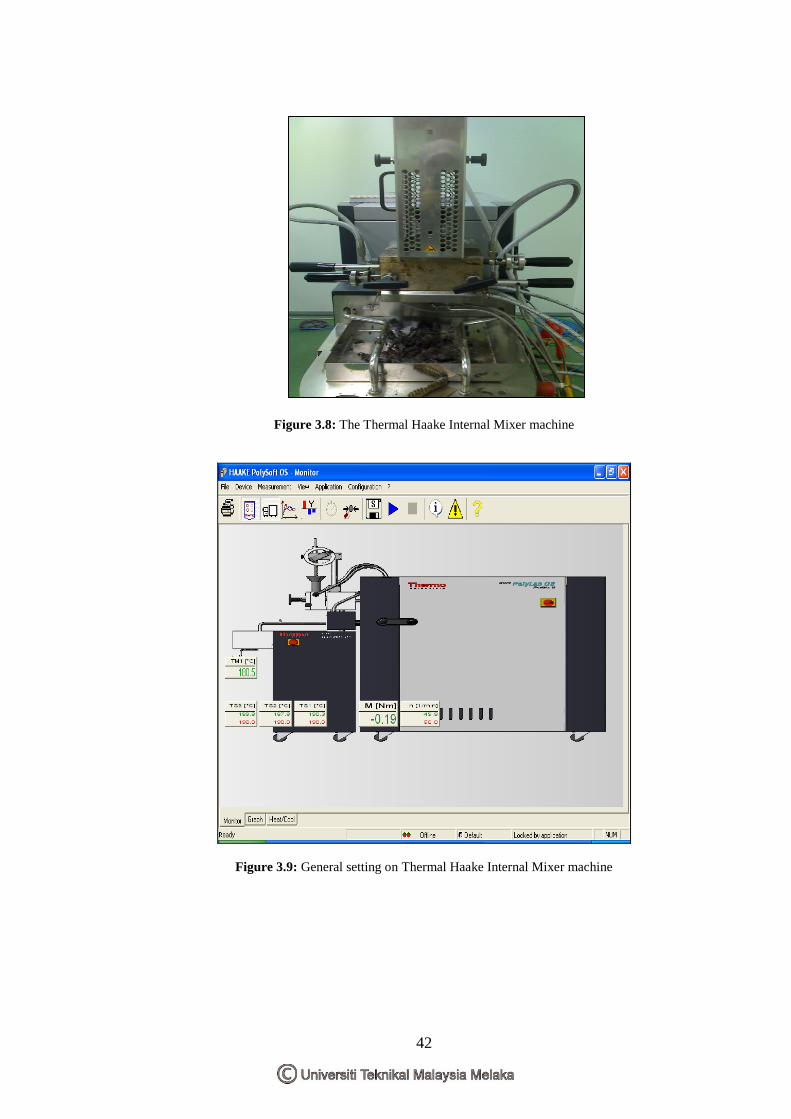
42
Figure 3.8: The Thermal Haake Internal Mixer machine
Figure 3.9: General setting on Thermal Haake Internal Mixer machine
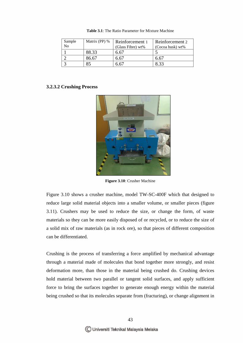
43
Table 3.1: The Ratio Parameter for Mixture Machine
Sample
No
Matrix (PP) % Reinforcement 1
(Glass Fibre) wt%
Reinforcement 2
(Cocoa husk) wt%
1 88.33 6.67 5
2 86.67 6.67 6.67
3 85 6.67 8.33
3.2.3.2 Crushing Process
Figure 3.10: Crusher Machine
Figure 3.10 shows a crusher machine, model TW-SC-400F which that designed to
reduce large solid material objects into a smaller volume, or smaller pieces (figure
3.11). Crushers may be used to reduce the size, or change the form, of waste
materials so they can be more easily disposed of or recycled, or to reduce the size of
a solid mix of raw materials (as in rock ore), so that pieces of different composition
can be differentiated.
Crushing is the process of transferring a force amplified by mechanical advantage
through a material made of molecules that bond together more strongly, and resist
deformation more, than those in the material being crushed do. Crushing devices
hold material between two parallel or tangent solid surfaces, and apply sufficient
force to bring the surfaces together to generate enough energy within the material
being crushed so that its molecules separate from (fracturing), or change alignment in
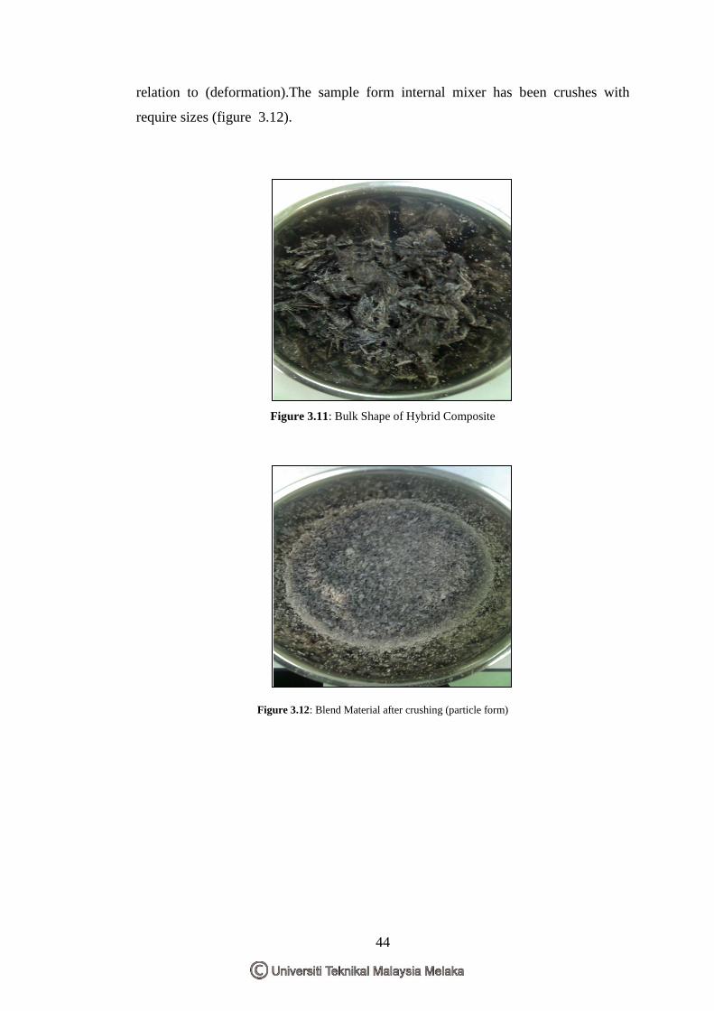
44
relation to (deformation).The sample form internal mixer has been crushes with
require sizes (figure 3.12).
Figure 3.11: Bulk Shape of Hybrid Composite
Figure 3.12: Blend Material after crushing (particle form)
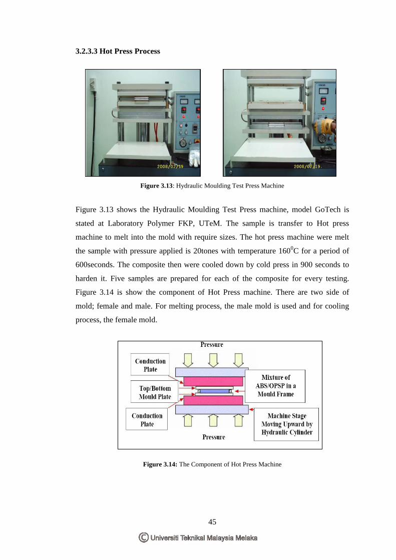
45
3.2.3.3 Hot Press Process
Figure 3.13: Hydraulic Moulding Test Press Machine
Figure 3.13 shows the Hydraulic Moulding Test Press machine, model GoTech is
stated at Laboratory Polymer FKP, UTeM. The sample is transfer to Hot press
machine to melt into the mold with require sizes. The hot press machine were melt
the sample with pressure applied is 20tones with temperature 1600C for a period of
600seconds. The composite then were cooled down by cold press in 900 seconds to
harden it. Five samples are prepared for each of the composite for every testing.
Figure 3.14 is show the component of Hot Press machine. There are two side of
mold; female and male. For melting process, the male mold is used and for cooling
process, the female mold.
Figure 3.14: The Component of Hot Press Machine
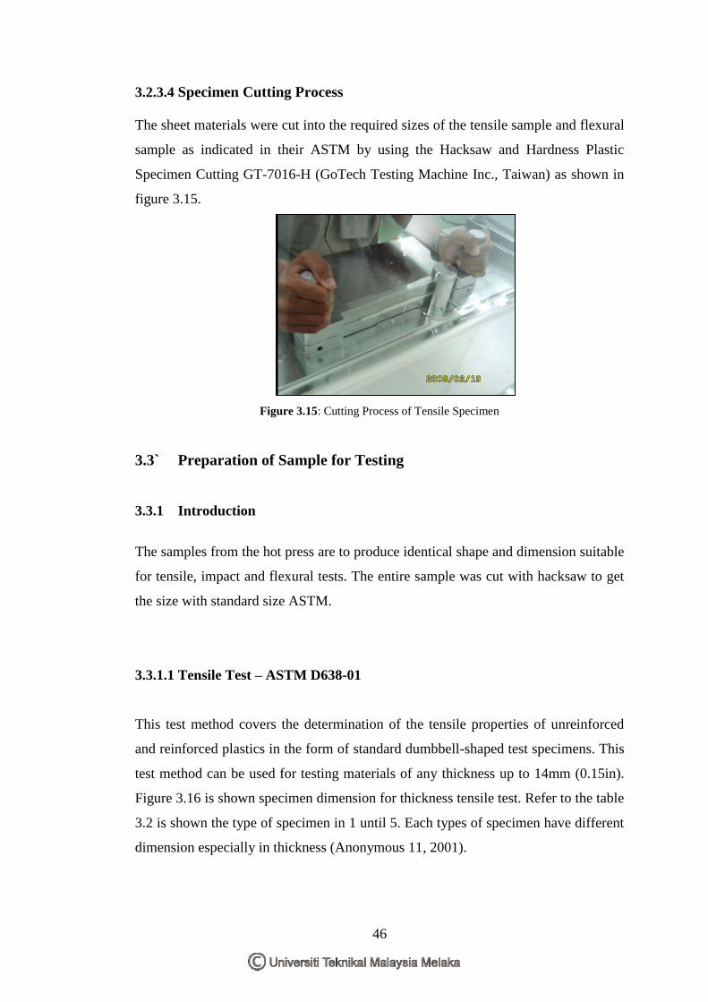
46
3.2.3.4 Specimen Cutting Process
The sheet materials were cut into the required sizes of the tensile sample and flexural
sample as indicated in their ASTM by using the Hacksaw and Hardness Plastic
Specimen Cutting GT-7016-H (GoTech Testing Machine Inc., Taiwan) as shown in
figure 3.15.
Figure 3.15: Cutting Process of Tensile Specimen
3.3` Preparation of Sample for Testing
3.3.1 Introduction
The samples from the hot press are to produce identical shape and dimension suitable
for tensile, impact and flexural tests. The entire sample was cut with hacksaw to get
the size with standard size ASTM.
3.3.1.1 Tensile Test – ASTM D638-01
This test method covers the determination of the tensile properties of unreinforced
and reinforced plastics in the form of standard dumbbell-shaped test specimens. This
test method can be used for testing materials of any thickness up to 14mm (0.15in).
Figure 3.16 is shown specimen dimension for thickness tensile test. Refer to the table
3.2 is shown the type of specimen in 1 until 5. Each types of specimen have different
dimension especially in thickness (Anonymous 11, 2001).
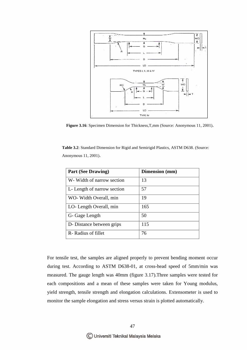
47
Figure 3.16: Specimen Dimension for Thickness,T,mm (Source: Anonymous 11, 2001).
Table 3.2: Standard Dimension for Rigid and Semirigid Plastics, ASTM D638. (Source:
Anonymous 11, 2001).
Part (See Drawing) Dimension (mm)
W- Width of narrow section 13
L- Length of narrow section 57
WO- Width Overall, min 19
LO- Length Overall, min 165
G- Gage Length 50
D- Distance between grips 115
R- Radius of fillet 76
For tensile test, the samples are aligned properly to prevent bending moment occur
during test. According to ASTM D638-01, at cross-head speed of 5mm/min was
measured. The gauge length was 40mm (figure 3.17).Three samples were tested for
each compositions and a mean of these samples were taken for Young modulus,
yield strength, tensile strength and elongation calculations. Extensometer is used to
monitor the sample elongation and stress versus strain is plotted automatically.
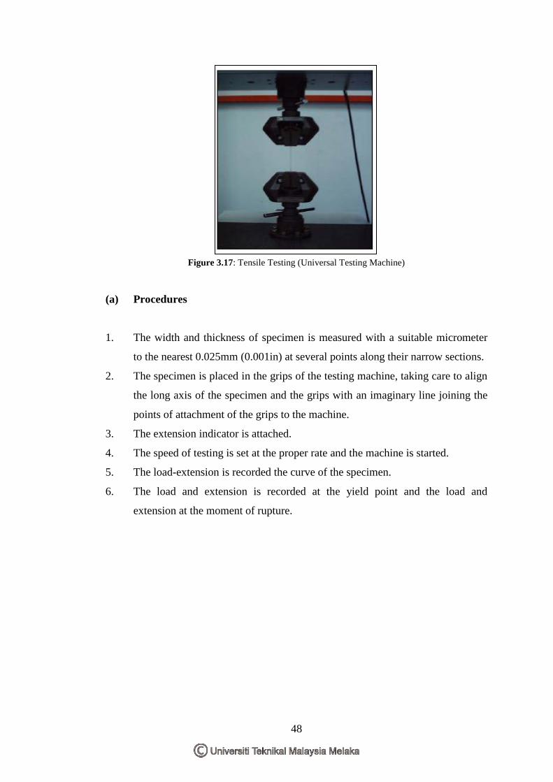
48
Figure 3.17: Tensile Testing (Universal Testing Machine)
(a) Procedures
1. The width and thickness of specimen is measured with a suitable micrometer
to the nearest 0.025mm (0.001in) at several points along their narrow sections.
2. The specimen is placed in the grips of the testing machine, taking care to align
the long axis of the specimen and the grips with an imaginary line joining the
points of attachment of the grips to the machine.
3. The extension indicator is attached.
4. The speed of testing is set at the proper rate and the machine is started.
5. The load-extension is recorded the curve of the specimen.
6. The load and extension is recorded at the yield point and the load and
extension at the moment of rupture.
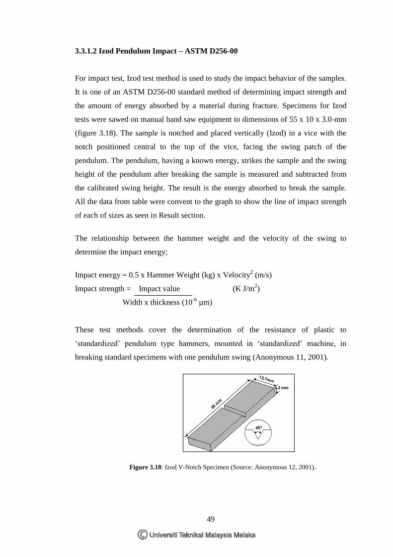
49
3.3.1.2 Izod Pendulum Impact – ASTM D256-00
For impact test, Izod test method is used to study the impact behavior of the samples.
It is one of an ASTM D256-00 standard method of determining impact strength and
the amount of energy absorbed by a material during fracture. Specimens for Izod
tests were sawed on manual band saw equipment to dimensions of 55 x 10 x 3.0-mm
(figure 3.18). The sample is notched and placed vertically (Izod) in a vice with the
notch positioned central to the top of the vice, facing the swing patch of the
pendulum. The pendulum, having a known energy, strikes the sample and the swing
height of the pendulum after breaking the sample is measured and subtracted from
the calibrated swing height. The result is the energy absorbed to break the sample.
All the data from table were convent to the graph to show the line of impact strength
of each of sizes as seen in Result section.
The relationship between the hammer weight and the velocity of the swing to
determine the impact energy;
Impact energy = 0.5 x Hammer Weight (kg) x Velocity2 (m/s)
Impact strength = Impact value (K J/m2)
Width x thickness (10-6
µm)
These test methods cover the determination of the resistance of plastic to
„standardized‟ pendulum type hammers, mounted in „standardized‟ machine, in
breaking standard specimens with one pendulum swing (Anonymous 11, 2001).
Figure 3.18: Izod V-Notch Specimen (Source: Anonymous 12, 2001).
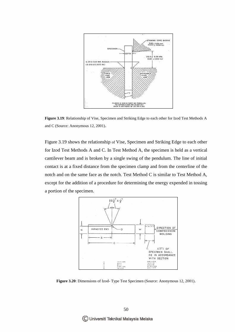
50
Figure 3.19: Relationship of Vise, Specimen and Striking Edge to each other for Izod Test Methods A
and C (Source: Anonymous 12, 2001).
Figure 3.19 shows the relationship of Vise, Specimen and Striking Edge to each other
for Izod Test Methods A and C. In Test Method A, the specimen is held as a vertical
cantilever beam and is broken by a single swing of the pendulum. The line of initial
contact is at a fixed distance from the specimen clamp and from the centerline of the
notch and on the same face as the notch. Test Method C is similar to Test Method A,
except for the addition of a procedure for determining the energy expended in tossing
a portion of the specimen.
Figure 3.20: Dimensions of Izod- Type Test Specimen (Source: Anonymous 12, 2001).
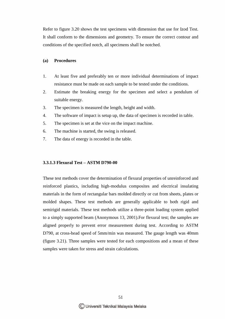
51
Refer to figure 3.20 shows the test specimens with dimension that use for Izod Test.
It shall conform to the dimensions and geometry. To ensure the correct contour and
conditions of the specified notch, all specimens shall be notched.
(a) Procedures
1. At least five and preferably ten or more individual determinations of impact
resistance must be made on each sample to be tested under the conditions.
2. Estimate the breaking energy for the specimen and select a pendulum of
suitable energy.
3. The specimen is measured the length, height and width.
4. The software of impact is setup up, the data of specimen is recorded in table.
5. The specimen is set at the vice on the impact machine.
6. The machine is started, the swing is released.
7. The data of energy is recorded in the table.
3.3.1.3 Flexural Test – ASTM D790-00
These test methods cover the determination of flexural properties of unreinforced and
reinforced plastics, including high-modulus composites and electrical insulating
materials in the form of rectangular bars molded directly or cut from sheets, plates or
molded shapes. These test methods are generally applicable to both rigid and
semirigid materials. These test methods utilize a three-point loading system applied
to a simply supported beam (Anonymous 13, 2001).For flexural test; the samples are
aligned properly to prevent error measurement during test. According to ASTM
D790, at cross-head speed of 5mm/min was measured. The gauge length was 40mm
(figure 3.21). Three samples were tested for each compositions and a mean of these
samples were taken for stress and strain calculations.
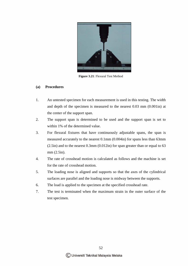
52
Figure 3.21: Flexural Test Method
(a) Procedures
1. An untested specimen for each measurement is used in this testing. The width
and depth of the specimen is measured to the nearest 0.03 mm (0.001in) at
the center of the support span.
2. The support span is determined to be used and the support span is set to
within 1% of the determined value.
3. For flexural fixtures that have continuously adjustable spans, the span is
measured accurately to the nearest 0.1mm (0.004in) for spans less than 63mm
(2.5in) and to the nearest 0.3mm (0.012in) for span greater than or equal to 63
mm (2.5in).
4. The rate of crosshead motion is calculated as follows and the machine is set
for the rate of crosshead motion.
5. The loading nose is aligned and supports so that the axes of the cylindrical
surfaces are parallel and the loading nose is midway between the supports.
6. The load is applied to the specimen at the specified crosshead rate.
7. The test is terminated when the maximum strain in the outer surface of the
test specimen.
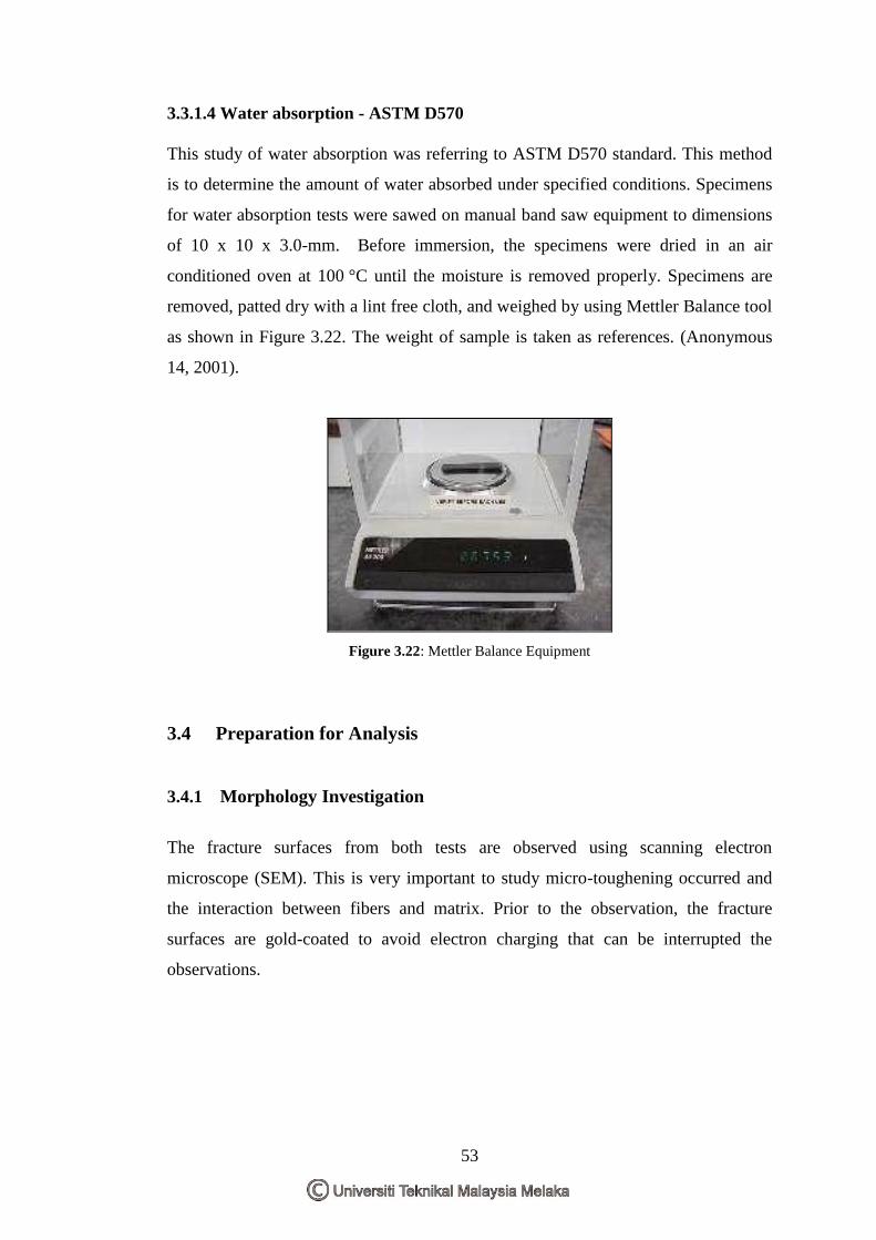
53
3.3.1.4 Water absorption - ASTM D570
This study of water absorption was referring to ASTM D570 standard. This method
is to determine the amount of water absorbed under specified conditions. Specimens
for water absorption tests were sawed on manual band saw equipment to dimensions
of 10 x 10 x 3.0-mm. Before immersion, the specimens were dried in an air
conditioned oven at 100 °C until the moisture is removed properly. Specimens are
removed, patted dry with a lint free cloth, and weighed by using Mettler Balance tool
as shown in Figure 3.22. The weight of sample is taken as references. (Anonymous
14, 2001).
Figure 3.22: Mettler Balance Equipment
3.4 Preparation for Analysis
3.4.1 Morphology Investigation
The fracture surfaces from both tests are observed using scanning electron
microscope (SEM). This is very important to study micro-toughening occurred and
the interaction between fibers and matrix. Prior to the observation, the fracture
surfaces are gold-coated to avoid electron charging that can be interrupted the
observations.
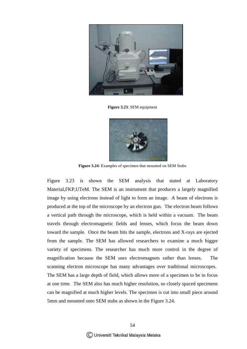
54
Figure 3.23: SEM equipment
Figure 3.24: Examples of specimen that mounted on SEM Stubs
Figure 3.23 is shown the SEM analysis that stated at Laboratory
Material,FKP,UTeM. The SEM is an instrument that produces a largely magnified
image by using electrons instead of light to form an image. A beam of electrons is
produced at the top of the microscope by an electron gun. The electron beam follows
a vertical path through the microscope, which is held within a vacuum. The beam
travels through electromagnetic fields and lenses, which focus the beam down
toward the sample. Once the beam hits the sample, electrons and X-rays are ejected
from the sample. The SEM has allowed researchers to examine a much bigger
variety of specimens. The researcher has much more control in the degree of
magnification because the SEM uses electromagnets rather than lenses. The
scanning electron microscope has many advantages over traditional microscopes.
The SEM has a large depth of field, which allows more of a specimen to be in focus
at one time. The SEM also has much higher resolution, so closely spaced specimens
can be magnified at much higher levels. The specimen is cut into small piece around
5mm and mounted onto SEM stubs as shown in the Figure 3.24.
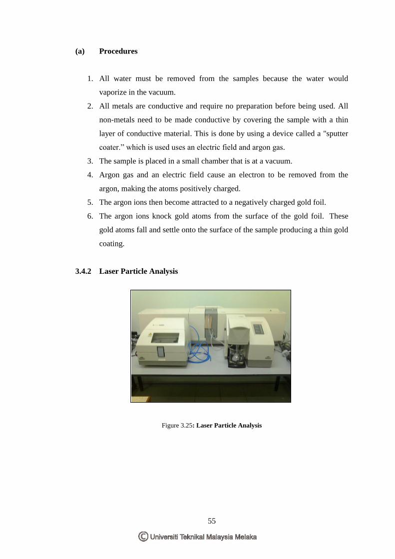
55
(a) Procedures
1. All water must be removed from the samples because the water would
vaporize in the vacuum.
2. All metals are conductive and require no preparation before being used. All
non-metals need to be made conductive by covering the sample with a thin
layer of conductive material. This is done by using a device called a "sputter
coater.” which is used uses an electric field and argon gas.
3. The sample is placed in a small chamber that is at a vacuum.
4. Argon gas and an electric field cause an electron to be removed from the
argon, making the atoms positively charged.
5. The argon ions then become attracted to a negatively charged gold foil.
6. The argon ions knock gold atoms from the surface of the gold foil. These
gold atoms fall and settle onto the surface of the sample producing a thin gold
coating.
3.4.2 Laser Particle Analysis
Figure 3.25: Laser Particle Analysis
56
Figure 3.25 shows the Laser Particle Analysis that used to analysis size of particle of
specimens. In a laser-based instrument, due to the near-parallel nature of the laser
beam, light scattering from the unimpeded laser beam is minimal because it is
focused into a beam stop until a particle passes through the instrument. As the laser
strikes the particle, light scatters and hits the photocell. Just like a white light
instrument, the change in voltage across the photocell is directly related to the size of
the particle. In the laser-based instrument, one looks at an increased signal against
what should be a zero background (in theory). Laser optical particle counters are
generally considered to be slightly more accurate and sensitive than white light
instruments. This machine is used to check the particle of cocoa powder to ensure the
size is acceptable in this research.
(a) Procedures
1. Make sure the sample is taken from the correct location using the correct
sampling procedure. Take steps to minimize sample contamination during
sample collection and be sure to leave headspace in the bottle.
2. Ensure the sample bottle is at least 2 ISO range codes cleaner than the desired
lowest levels of ISO fluid cleanliness.
3. Dilute viscous fluids and heavily contaminated samples using prefiltered
reagent grade kerosene prior to particle counting (remember to recalculate the
original particle count concentrations using the appropriate dilution factor).
Prefilter the diluent if its cleanliness is in question.
4. Test for free and emulsified water using a crackle test or other moisture
screening method. If water is present, the water may be vacuum dehydrated
or treated by mixing the oil 50:50 with a tonic comprised of three parts
toluene and one part isopropyl alcohol.
5. If more than a few minutes pass between sampling and testing, resuspend the
particles by agitating the sample for five minutes (longer for viscous fluids)
in a paint shaker.
6. Ensure that the effects due to air bubbles are negated by using vacuum
ultrasonic bath and/or a vacuum de-greasing - preferably both, starting with
the ultrasonic bath (optical particle counters).
57
7. Don‟t leave onsite particle counter idle on the shelf make the most of this
valuable asset each and every day.
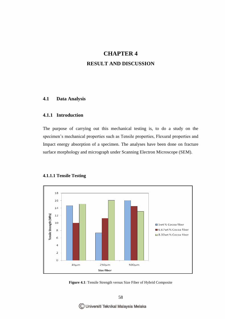
58
CHAPTER 4
RESULT AND DISCUSSION
4.1 Data Analysis
4.1.1 Introduction
The purpose of carrying out this mechanical testing is, to do a study on the
specimen‟s mechanical properties such as Tensile properties, Flexural properties and
Impact energy absorption of a specimen. The analyses have been done on fracture
surface morphology and micrograph under Scanning Electron Microscope (SEM).
4.1.1.1 Tensile Testing
Figure 4.1: Tensile Strength versus Size Fiber of Hybrid Composite
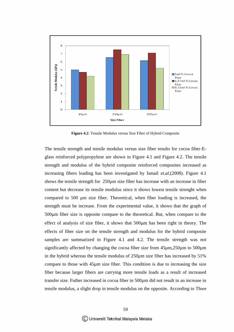
59
Figure 4.2: Tensile Modulus versus Size Fiber of Hybrid Composite
The tensile strength and tensile modulus versus size fiber results for cocoa fiber-E-
glass reinforced polypropylene are shown in Figure 4.1 and Figure 4.2. The tensile
strength and modulus of the hybrid composite reinforced composites increased as
increasing fibers loading has been investigated by Ismail et.al,(2008). Figure 4.1
shows the tensile strength for 250µm size fiber has increase with an increase in fiber
content but decrease its tensile modulus since it shows lowest tensile strenght when
compared to 500 µm size fiber. Theoretical, when fiber loading is increased, the
strength must be increase. From the experimental value, it shows that the graph of
500µm fiber size is opposite compare to the theoretical. But, when compare to the
effect of analysis of size fiber, it shows that 500µm has been right in theory. The
effects of fiber size on the tensile strength and modulus for the hybrid composite
samples are summarized in Figure 4.1 and 4.2. The tensile strength was not
significantly affected by changing the cocoa fiber size from 45µm,250µm to 500µm
in the hybrid whereas the tensile modulus of 250µm size fiber has increased by 51%
compare to those with 45µm size fiber. This condition is due to increasing the size
fiber because larger fibers are carrying more tensile loads as a result of increased
transfer size. Futher increased in cocoa fiber in 500µm did not result in an increase in
tensile modulus, a slight drop in tensile modulus on the opposite. According to Thwe
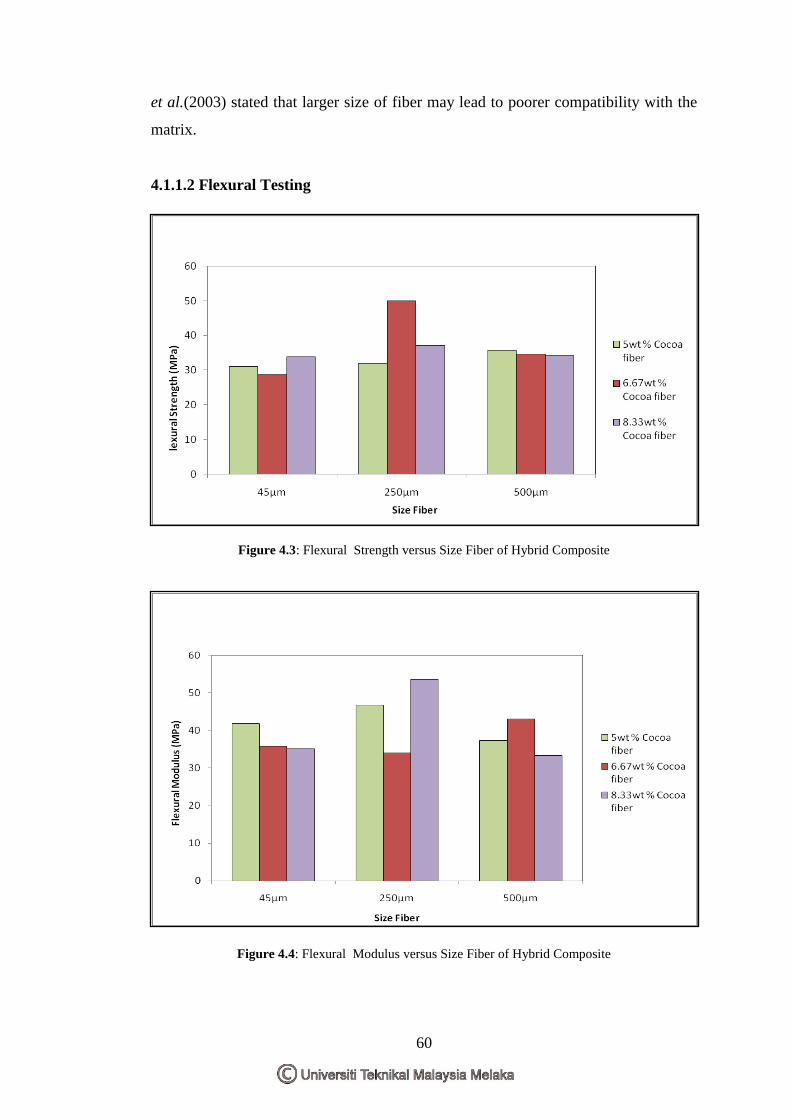
60
et al.(2003) stated that larger size of fiber may lead to poorer compatibility with the
matrix.
4.1.1.2 Flexural Testing
Figure 4.3: Flexural Strength versus Size Fiber of Hybrid Composite
Figure 4.4: Flexural Modulus versus Size Fiber of Hybrid Composite
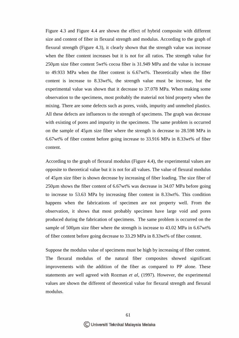
61
Figure 4.3 and Figure 4.4 are shown the effect of hybrid composite with different
size and content of fiber in flexural strength and modulus. According to the graph of
flexural strength (Figure 4.3), it clearly shown that the strength value was increase
when the fiber content increases but it is not for all ratios. The strength value for
250µm size fiber content 5wt% cocoa fiber is 31.949 MPa and the value is increase
to 49.933 MPa when the fiber content is 6.67wt%. Theoretically when the fiber
content is increase to 8.33wt%, the strength value must be increase, but the
experimental value was shown that it decrease to 37.078 MPa. When making some
observation to the specimens, most probably the material not bind property when the
mixing. There are some defects such as pores, voids, impurity and unmelted plastics.
All these defects are influences to the strength of specimens. The graph was decrease
with existing of pores and impurity in the specimens. The same problem is occurred
on the sample of 45µm size fiber where the strength is decrease to 28.598 MPa in
6.67wt% of fiber content before going increase to 33.916 MPa in 8.33wt% of fiber
content.
According to the graph of flexural modulus (Figure 4.4), the experimental values are
opposite to theoretical value but it is not for all values. The value of flexural modulus
of 45µm size fiber is shown decrease by increasing of fiber loading. The size fiber of
250µm shows the fiber content of 6.67wt% was decrease in 34.07 MPa before going
to increase to 53.63 MPa by increasing fiber content in 8.33wt%. This condition
happens when the fabrications of specimen are not property well. From the
observation, it shows that most probably specimen have large void and pores
produced during the fabrication of specimens. The same problem is occurred on the
sample of 500µm size fiber where the strength is increase to 43.02 MPa in 6.67wt%
of fiber content before going decrease to 33.29 MPa in 8.33wt% of fiber content.
Suppose the modulus value of specimens must be high by increasing of fiber content.
The flexural modulus of the natural fiber composites showed significant
improvements with the addition of the fiber as compared to PP alone. These
statements are well agreed with Rozman et al, (1997). However, the experimental
values are shown the different of theoretical value for flexural strength and flexural
modulus.
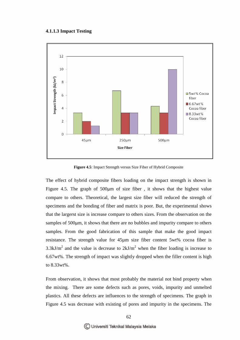
62
4.1.1.3 Impact Testing
Figure 4.5: Impact Strength versus Size Fiber of Hybrid Composite
The effect of hybrid composite fibers loading on the impact strength is shown in
Figure 4.5. The graph of 500µm of size fiber , it shows that the highest value
compare to others. Theoretical, the largest size fiber will reduced the strength of
specimens and the bonding of fiber and matrix is poor. But, the experimental shows
that the largerst size is increase compare to others sizes. From the observation on the
samples of 500µm, it shows that there are no bubbles and impurity compare to others
samples. From the good fabrication of this sample that make the good impact
resistance. The strength value for 45µm size fiber content 5wt% cocoa fiber is
3.3kJ/m2 and the value is decrease to 2kJ/m
2 when the fiber loading is increase to
6.67wt%. The strength of impact was slightly dropped when the filler content is high
to 8.33wt%.
From observation, it shows that most probably the material not bind property when
the mixing. There are some defects such as pores, voids, impurity and unmelted
plastics. All these defects are influences to the strength of specimens. The graph in
Figure 4.5 was decrease with existing of pores and impurity in the specimens. The
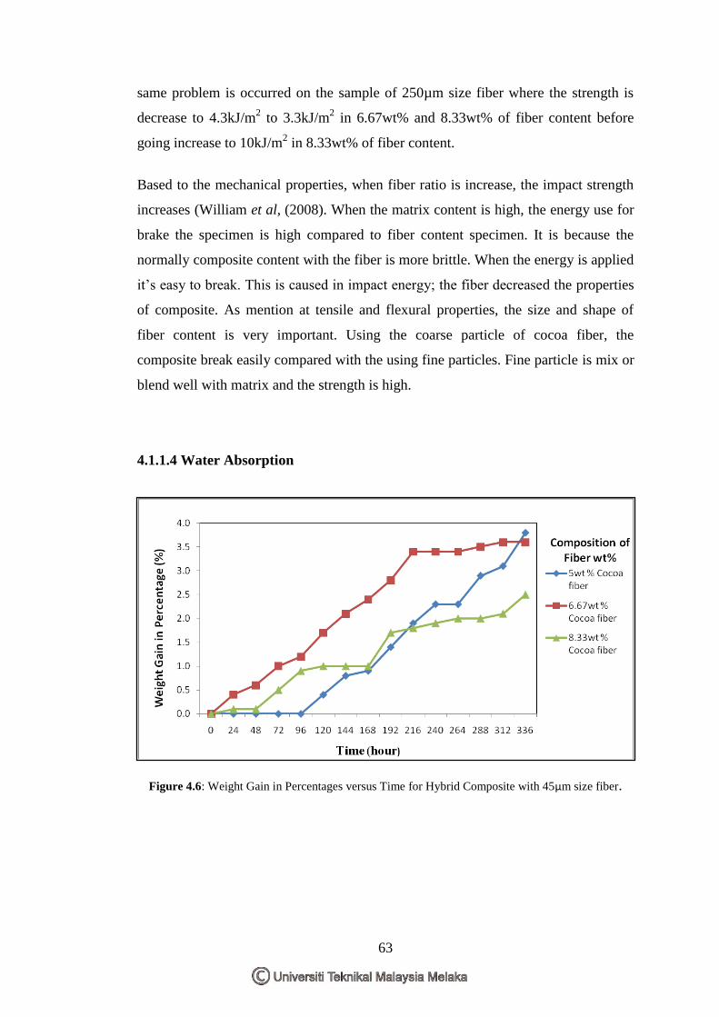
63
same problem is occurred on the sample of 250µm size fiber where the strength is
decrease to 4.3kJ/m2 to 3.3kJ/m
2 in 6.67wt% and 8.33wt% of fiber content before
going increase to 10kJ/m2 in 8.33wt% of fiber content.
Based to the mechanical properties, when fiber ratio is increase, the impact strength
increases (William et al, (2008). When the matrix content is high, the energy use for
brake the specimen is high compared to fiber content specimen. It is because the
normally composite content with the fiber is more brittle. When the energy is applied
it‟s easy to break. This is caused in impact energy; the fiber decreased the properties
of composite. As mention at tensile and flexural properties, the size and shape of
fiber content is very important. Using the coarse particle of cocoa fiber, the
composite break easily compared with the using fine particles. Fine particle is mix or
blend well with matrix and the strength is high.
4.1.1.4 Water Absorption
Figure 4.6: Weight Gain in Percentages versus Time for Hybrid Composite with 45µm size fiber.
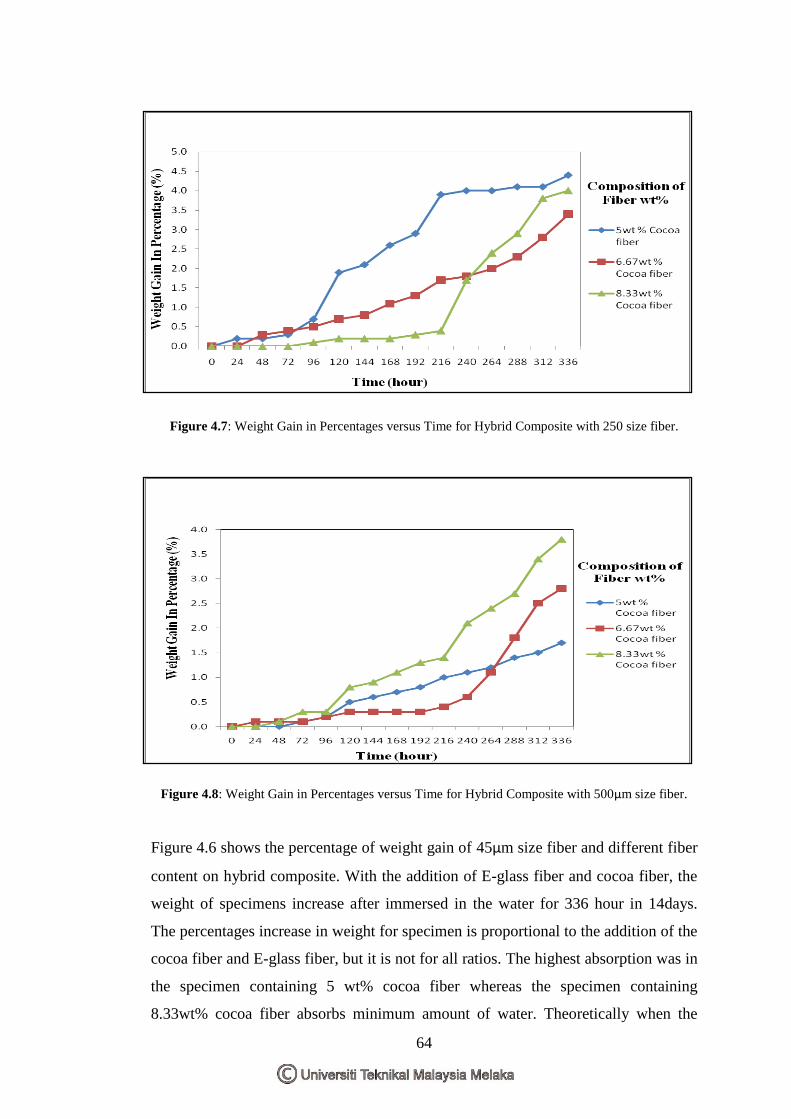
64
Figure 4.7: Weight Gain in Percentages versus Time for Hybrid Composite with 250 size fiber.
Figure 4.8: Weight Gain in Percentages versus Time for Hybrid Composite with 500µm size fiber.
Figure 4.6 shows the percentage of weight gain of 45µm size fiber and different fiber
content on hybrid composite. With the addition of E-glass fiber and cocoa fiber, the
weight of specimens increase after immersed in the water for 336 hour in 14days.
The percentages increase in weight for specimen is proportional to the addition of the
cocoa fiber and E-glass fiber, but it is not for all ratios. The highest absorption was in
the specimen containing 5 wt% cocoa fiber whereas the specimen containing
8.33wt% cocoa fiber absorbs minimum amount of water. Theoretically when the
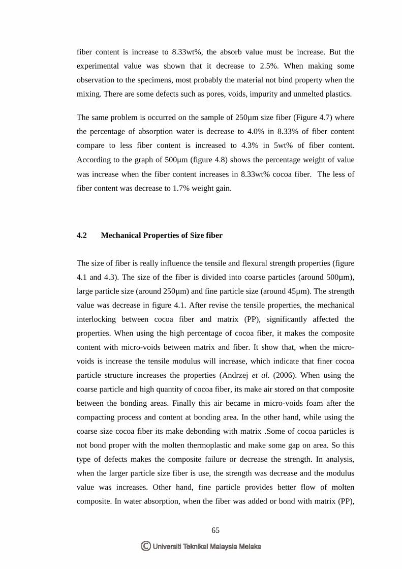
65
fiber content is increase to 8.33wt%, the absorb value must be increase. But the
experimental value was shown that it decrease to 2.5%. When making some
observation to the specimens, most probably the material not bind property when the
mixing. There are some defects such as pores, voids, impurity and unmelted plastics.
The same problem is occurred on the sample of 250µm size fiber (Figure 4.7) where
the percentage of absorption water is decrease to 4.0% in 8.33% of fiber content
compare to less fiber content is increased to 4.3% in 5wt% of fiber content.
According to the graph of 500µm (figure 4.8) shows the percentage weight of value
was increase when the fiber content increases in 8.33wt% cocoa fiber. The less of
fiber content was decrease to 1.7% weight gain.
4.2 Mechanical Properties of Size fiber
The size of fiber is really influence the tensile and flexural strength properties (figure
4.1 and 4.3). The size of the fiber is divided into coarse particles (around 500µm),
large particle size (around 250µm) and fine particle size (around 45µm). The strength
value was decrease in figure 4.1. After revise the tensile properties, the mechanical
interlocking between cocoa fiber and matrix (PP), significantly affected the
properties. When using the high percentage of cocoa fiber, it makes the composite
content with micro-voids between matrix and fiber. It show that, when the micro-
voids is increase the tensile modulus will increase, which indicate that finer cocoa
particle structure increases the properties (Andrzej et al. (2006). When using the
coarse particle and high quantity of cocoa fiber, its make air stored on that composite
between the bonding areas. Finally this air became in micro-voids foam after the
compacting process and content at bonding area. In the other hand, while using the
coarse size cocoa fiber its make debonding with matrix .Some of cocoa particles is
not bond proper with the molten thermoplastic and make some gap on area. So this
type of defects makes the composite failure or decrease the strength. In analysis,
when the larger particle size fiber is use, the strength was decrease and the modulus
value was increases. Other hand, fine particle provides better flow of molten
composite. In water absorption, when the fiber was added or bond with matrix (PP),
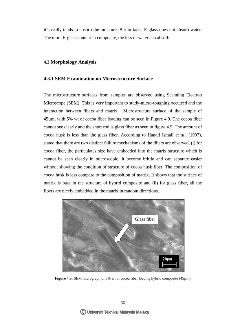
66
it‟s really tends to absorb the moisture. But in facts, E-glass does not absorb water.
The more E-glass content in composite, the less of water can absorb.
4.3 Morphology Analysis
4.3.1 SEM Examination on Microstructure Surface
The microstructure surfaces from samples are observed using Scanning Electron
Microscope (SEM). This is very important to study-micro-toughing occurred and the
interaction between fibers and matrix. Microstructure surface of the sample of
45µm, with 5% wt of cocoa fiber loading can be seen in Figure 4.9. The cocoa fiber
cannot see clearly and the short rod is glass fiber as seen in figure 4.9. The amount of
cocoa husk is less than the glass fiber. According to Hanafi Ismail et al., (1997),
stated that there are two distinct failure mechanisms of the fibers are observed, (i) for
cocoa fiber, the particulates size have embedded into the matrix structure which is
cannot be seen clearly in microscopic. It become brittle and can separate easier
without showing the condition of structure of cocoa husk fiber. The composition of
cocoa husk is less compare to the composition of matrix. It shows that the surface of
matrix is base in the structure of hybrid composite and (ii) for glass fiber, all the
fibers are nicely embedded in the matrix in random directions.
Figure 4.9: SEM micrograph of 5% wt of cocoa fiber loading hybrid composite (45µm)
Glass fiber
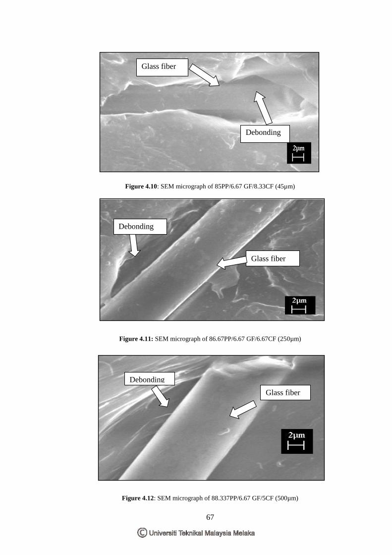
67
Figure 4.10: SEM micrograph of 85PP/6.67 GF/8.33CF (45µm)
Figure 4.11: SEM micrograph of 86.67PP/6.67 GF/6.67CF (250µm)
Figure 4.12: SEM micrograph of 88.337PP/6.67 GF/5CF (500µm)
Glass fiber
Debonding
Glass fiber
Debonding
g
Debonding
Glass fiber
68
From the SEM micrographs in Figure 4.10, it can be observed that glass fiber is
embedded into the matrix phase. The cocoa husk fiber is not clear in this figure. The
bonding of glass fiber and matrix is poor. But, the cocoa husk has good bonding with
the matrix in composite. It influences with the size of fibers. The smallest size will be
strong bonding to the matrix. Figure 4.11 are shown the micrograph of 86.67PP/6.67
GF/6.67CF which the size of cocoa fiber is 250µm. The bonding between the matrix
and glass fiber are poor. This structure are not immerse with any coupling agents.
The structure of cocoa husk bond with matrix is not clear. From the SEM
micrographs in Figure 4.12, it can be observed that glass fiber has poor wetting
debonding with matrix phase. These structures are not using any coupling agents.
These failure happen that might be caused that denoted as reduction in strength.
Unlike uniform synthetic fibers, irregularly shaped of fillers, their capability to
support stress from matrix is rather poor. The micrographs also show that there are
no interaction in between fibers and matrix. In evaluation, it shows that the cocoa
fiber-glass fiber reinforced with matrix has poor bonding. It looks that, the glass fiber
cannot be strong to bond with matrix and the cocoa particle can bond with matrix
properly.
69
CHAPTER 5
CONCLUSIONS AND RECOMMENDATIONS
5.1 Conclusions
The effects of natural fiber reinforced hybrid composite have been investigated as a
function of fiber loading, ratio and size fiber. The present work showed that the E-
glass fiber reinforced composite showed a contradictory result in view of the fact that
its mechanical properties should greater than the PP alone. The decreasing of the
mechanical properties was found attributed by incompatibility between the
reinforcement and matrix. From water absorption observation, the highest amount of
fibers will gives higher absorption of water and the highest resistance of water will
effect through the same amount of fiber. The better sample is 5wt% fiber loading for
500µm size fiber .The comparison of size of fibers; it shows that the biggest size will
absorb more water compare to the smallest sizes and the same amount of fiber will
exhibit greater resistance to water enters. The defect of specimen can give an effect
to water absorb. The effect of different sizes of cocoa husk fiber on the impact
strength has been explained in „Discussion‟ section. The combination of coca husk
and E-glass in this present work improved the impact strength of the hybrid
composites. The impact strength increased as increasing the fiber loading. The better
sample is (10KJ/m2) for 500µm size fiber in 8.33wt% fiber loading.
This is because E-glass provided sufficient and better interfacial adhesion between
fibers and matrix. This behavior strengthens the composites especially under impact
loading. The impact strength of the hybrid composite depends on the amount of fiber
and the type of testing .In case of notched samples, the impact strength increases
with the amount of fibers added until a plateau is reached.
Generally, the mechanical properties of PP/E-glass composite can be improved by
adding the natural fiber (cocoa husk) particle, except for the flexural modulus. The
70
better flexural strength is (49.933 MPa) for 250µm size fiber in 6.67wt% fiber
loading and the better tensile strength is (16.07 MPa) for 250µm size fiber in
8.33wt% fiber loading.
The results showed that the natural fiber filled PP/E-glass hybrid composite had
increased the tensile strength and tensile modulus as the loading of charcoal filler
increased. Through study of morphology on the microstructure surface, it was found
that the adhesion between the PP and E-glass fiber was poor. It is because this
experiment is not using any coupling agents, but, other method is by using natural
fiber also can solve this problem. For cocoa fiber, the particulates size have
embedded into the matrix structure which is cannot be seen clearly in microscopic.
5.2 Recommendations
From this work, the following recommendations on the future work are:
a) Do the treatment on the natural fiber before mix with others material between
the PP and E-glass fiber in the E-glass fiber reinforced polypropylene
specimen. The suggestions such as applying the coupling agent or the
chemical modification that will develop strong bond between fiber and matrix
of the PP matrix and can enhance their mechanical properties.
b) The specimen should prepared by using various process parameters settings
in order to study the effect of fiber loading on processing parameters.
a) - varies % of cocoa husk and glass fiber.
b) - minimize the size of cocoa husk and glass fiber.
c) In future, from the investigation on cocoa husk-glassfiber/polypropylene
hybrid composite, it can be use in producing product for the industries such
as furniture and so on.
71
REFERENCES
Adomako, D. (1975) . “A review of researches into the commercial utilisation of
cocoa by-products with particular references to the prospects in Ghana.” Research
Review CMB Newsletter No. 61 pp. 12-20.
Anand R. Sanadi, Daniel F. Caulfield, and Rodney E. Jacobson, (1997).“Paper And
Composites From Agro-Based Resources.” Boca Raton: CRC Press : Lewis
Publishers, c1997. Pages 377-401: Chapter 12 Agro-Fiber Thermoplastic Composites
Andrzej K. Bledzeki, Omar Farukh. (2006). “Microcellular Injection Molded Wood
fiber PP composite.” Journal of Cellular Plastics. Vol 42, No 63, pp 2-15.
Anonymous, 1. (2001). “PMC”. , Sri Consulting Business Intelligence Yahoo
[Online]. Available at http://www.sric.bi.com/explorer/PMC.shtm/ (Accessed : 14
April 2009)
Anonymous 2 ,(2009). “metal matrix compoaite”. Yahoo [Online]. Available at
http://www.answer.com/topic/metal_matrix_composite. (Accessed : 14 April 2009)
Anonymous 3, (2009). Available at
http://material.globalspec.com/learnmore/material_chemical_adhesive/plastic_elasto
mers_polymers/thermo. [online]. (Accessed: 14 April 2009)
Anonymous 4 “Composite/Plstic, (2009).. Available at
http://composite.about.com/od/aboutcomposites plastic/1/99060297.htm. (Accessed
:14April 2009)
Anonymous 5 ,“Hybrid Composite”, (2009)., Google [Online]. Available at
http://www.doctorspiller.com/dental_materials.htm. (Accessed :14 April 2009)
72
Anonymous 6 (2004). “Malaysian Cocoa Board.” [Online]. Available at
http://www.koko.gov.my/lkm/index.cfm. (Accessed : 14 April 2009)
Anonymous 7,(2009). “glassfiber”. Yahoo [Online]. Available at
http://www.wikipedia .answer.com/topic/glassfibert . (Accessed : 14 April 2009)
Anonymous 8. (2009). Available at http://www.answers.com/topic/polypropylene.
Yahoo [Online]. (Accessed : 14 April 2009)
Anonymous 9,(2009). “impact test”. Yahoo [Online]. Available at
http://www.wikipedia .answer.com/topic/impact _test . (Accessed : 14 April 2009)
Anonymous 10,(2009). “flexural test”. Yahoo [Online]. Available at
http://www.wikipedia .answer.com/topic/flexural_test . (Accessed : 14 April 2009)
Anonymous 11 (2001). American Society of Testing Materials. (2001 ).“Standard
Test Method for Tensile Properties of Plastics.” US: D 638 – 01
Anonymous 12 (2001). American Society of Testing Materials. ( )“Standard Test
Method for Izod Impact Properties of Plastics.” US: D256-00
Anonymous 13, (2001) .American Society of Testing Materials. (2001).“Flexural
Properties of Unreinforced and Reinforced Plastics and Electrical Insulating
Materials.” US: D 790 – 00
Anonymous 14,( 2001).American Society of Testing Materials. (2001).“Standard
Test Method for Water Absorption of Plastics.” US: D 570 – 98
Arib, R.M.N., Sapuan, S.M., Ahmad, M.M.H.M., Paridah, M.T., & Khairul Zaman,
H.M.D.. (2006). Mechanical properties of pineapple leaf fiber reinforced
polypropylene composites. Materials and Design, 27: 391–396.
Bismarck, A., Amar ,Mohanty,K ,Ibon Aranberri-Askargorta,†§a Syliva Czapla,c
Manjusri Misra,‡b Georg Hinrichsenb and Jürgen Springera,‟ “Surface
73
characterization of natural fibers; surface properties and the water up-take behavior
of modified sisal and coir fibers”, Universität Berlin, Institut für Nichtmetallische
Werkstoffe, Polymerphysik, Sekr., 30th March 2001
Bessadok, A., Marais, S., Gouanve, F., Colasse, L., Zimmerlin, I., Roudesli, &
S.Me´tayer. M.(2007). Effect of chemical treatments of Alfa (Stipa tenacissima)
fibres on water-sorption properties. Composites Science and Technology, 67:685–
697.
Beckwith, W. (2008) ”Natural Fibers: Nature Providing Technology for
Composites”,SAMPE International Technical Director and President, BTG
Composites Inc., Taylorsville, UT SAMPE Journal, Volume 44, No. 3,
Callister,Jr. (2003). “Materials Science and Engineering an Introduction.” Sixth
edition: John Wiley & Sons Press, pp 544-554
Dalvag,H. C. Klason and H.S. Stromvall, “The efficiency of cellulosic filles in
common thermoplastics. Filling with processing aids and coupling agents,” Int J
Polym Mater 11 (1985) (1), pp. 9–38.
Gilbert and Richard D. (1994). “Cellulosic Polymers, Blends and Composites”. New
York: Hanser Publishers: pp.115–130; Chapter 6.
Ismail, H, Rosnah, N., & Rozman, H.D. (1997). “Effects of various bonding system
on mechanical properties of oil – palm fiber reinforced rubber composites”.
European Journal of Polymers, 33(8):pp1231-1238.
Ismail, A.E,and Nor Azila Zamani, (2008). “Tensile and Impact Behavior of Hybrid
Extruded Glass/Natural Fiber Reinforced Polypropylene Composites”. Faculty of
Mec. & anufacturing Eng., UTHM.
74
Katz, H.S, and J.V. Mileswski. (1987). “Handbook of Fillers for Plastics”. Van
Nostrand Reinhold, New York, NY
Naslain, R. (2009). “Material Synthesis and Processing”pp. 213. Available at
www.mpg.de/pdf/europeanWhiteBook/wb_material_213_216.pdf
Owolarafe1, b.s. Ogunsina, a.s. Gbadamosi and O.o. Fabunmi,(1997) „Application
Of Coefficient Of Friction To The Separation Of Cocoa Husk–Beans Mixture‟,
Department of Agricultural Engineering Obafemi Awolowo University Ile-Ife,
Nigeria .Accepted for Publication February 20, 2007
Razi, R. Portier and A. Raman, Studies on polymer–wood interface bonding: effect
of coupling agents and surface modification, J Compos Mater 33 (1999) (12), pp.
1064–1079
Rozman, H.D, Tay, G.S, Kumar, R.N, Abusamah, A., Ismail, H. and Mohd Ishak,
Z.A. (2001). “Polypropylene-Oil Palm Empty Fruit Bunch-Glass Fiber Hybrid
Composites In A Preliminary Study On The Flexural And Tensile Properties”.
European Polymer Journal, 37:1283-1291.
Rowell, R.M, Anand Sanadi, Jacobson, R., and Caulfield, D (1999).“Properties of
Kenaf/Polypropylene Composite.” Ag & Bio Engineering,. pp. 381-392. ISBN 0-
9670559-0-3. Chapter 32
Roylance, D.,(2000). “ Introduction to Composite Materials”. Massachusetts Institute
of Technology, Department of Materials Science and Engineering, , MA 02139
Saira, Munawar Ali Munawar, and Shafi ullah Khan, (2007)‟ Natural Fiber-
Reinforced Polymer Composites‟,Applied Chemistry Research Centre, PCSIR Labs
Complex, Lahore-54600, Pakistan, and 2Institute of Chemistry, University of the
Punjab, Lahore, Pakistan.Received April 2006, accepted March 2007
75
Thwe, Liao K. “Effects of environmental ageing on the mechanical properties of
bamboo-glass fiber reinforced polymer matrix hybrid composites”. Compos Part A
2002;33:43–52.
Tuah A.K. and Orskov E.R. “The Degradation of Untreated and Treated Maize cobs
and Cocoa Pod Husks in the Rumen”. Department of Animal Science. Available at
http://www.ilri.org/infoserv/webpub/fulldocs/x5490e/x5490e0t.htm.[online].
(Accessed : 14 April 2009)
William ,G. Escobar. (2008). “Influence of wood species in properties of
wood/HDPE composite: Thesis”, Washington State University.
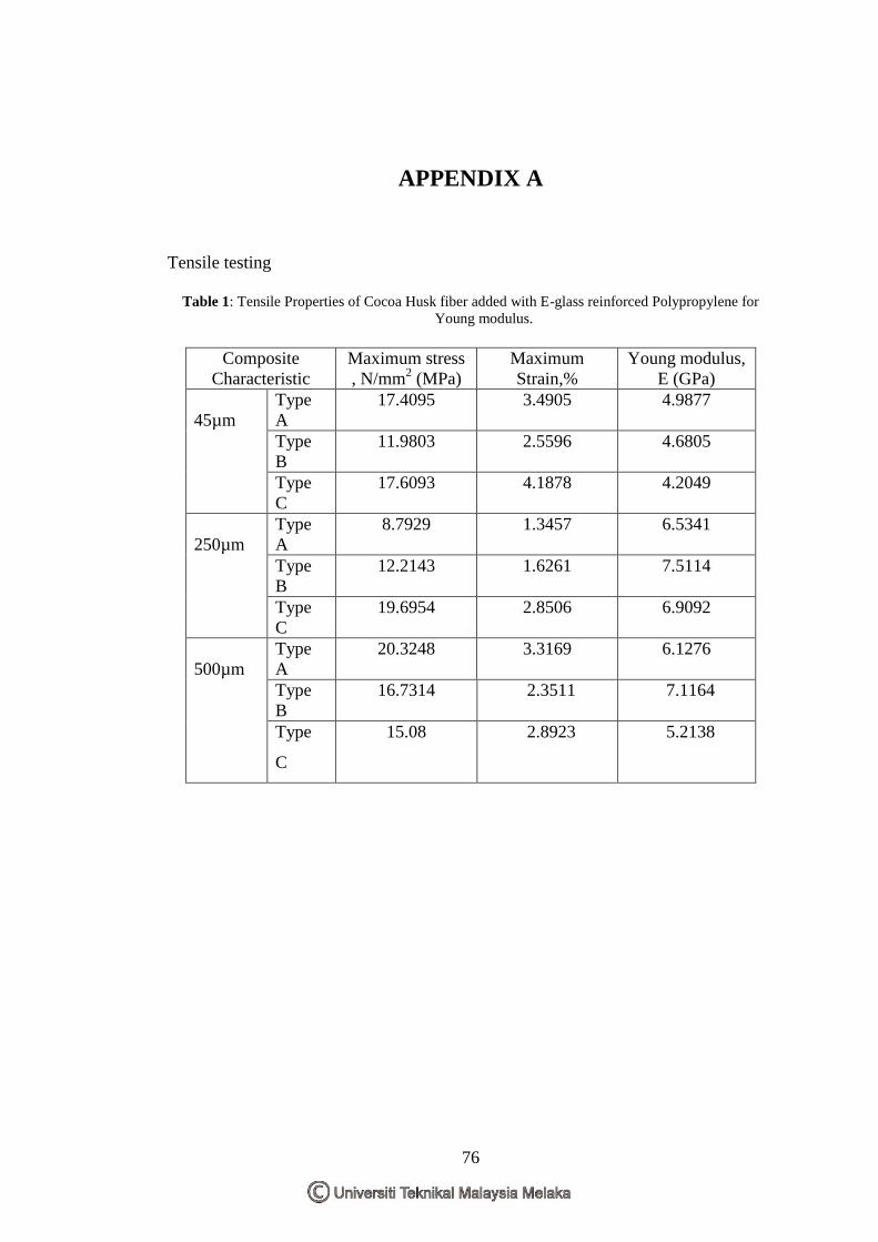
76
APPENDIX A
Tensile testing
Table 1: Tensile Properties of Cocoa Husk fiber added with E-glass reinforced Polypropylene for
Young modulus.
Composite
Characteristic
Maximum stress
, N/mm2 (MPa)
Maximum
Strain,%
Young modulus,
E (GPa)
45µm
Type
A
17.4095 3.4905 4.9877
Type
B
11.9803 2.5596 4.6805
Type
C
17.6093 4.1878 4.2049
250µm
Type
A
8.7929 1.3457 6.5341
Type
B
12.2143 1.6261 7.5114
Type
C
19.6954 2.8506 6.9092
500µm
Type
A
20.3248 3.3169 6.1276
Type
B
16.7314 2.3511 7.1164
Type
C
15.08 2.8923 5.2138
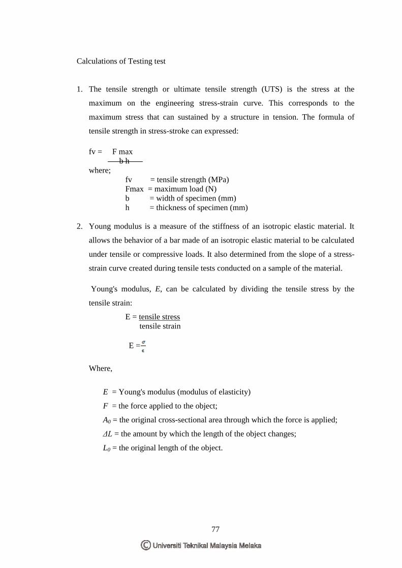
77
Calculations of Testing test
1. The tensile strength or ultimate tensile strength (UTS) is the stress at the
maximum on the engineering stress-strain curve. This corresponds to the
maximum stress that can sustained by a structure in tension. The formula of
tensile strength in stress-stroke can expressed:
fv = F max
b h
where;
fv = tensile strength (MPa)
Fmax = maximum load (N)
b = width of specimen (mm)
h = thickness of specimen (mm)
2. Young modulus is a measure of the stiffness of an isotropic elastic material. It
allows the behavior of a bar made of an isotropic elastic material to be calculated
under tensile or compressive loads. It also determined from the slope of a stress-
strain curve created during tensile tests conducted on a sample of the material.
Young's modulus, E, can be calculated by dividing the tensile stress by the
tensile strain:
E = tensile stress
tensile strain
E =
Where,
E = Young's modulus (modulus of elasticity)
F = the force applied to the object;
A0 = the original cross-sectional area through which the force is applied;
ΔL = the amount by which the length of the object changes;
L0 = the original length of the object.
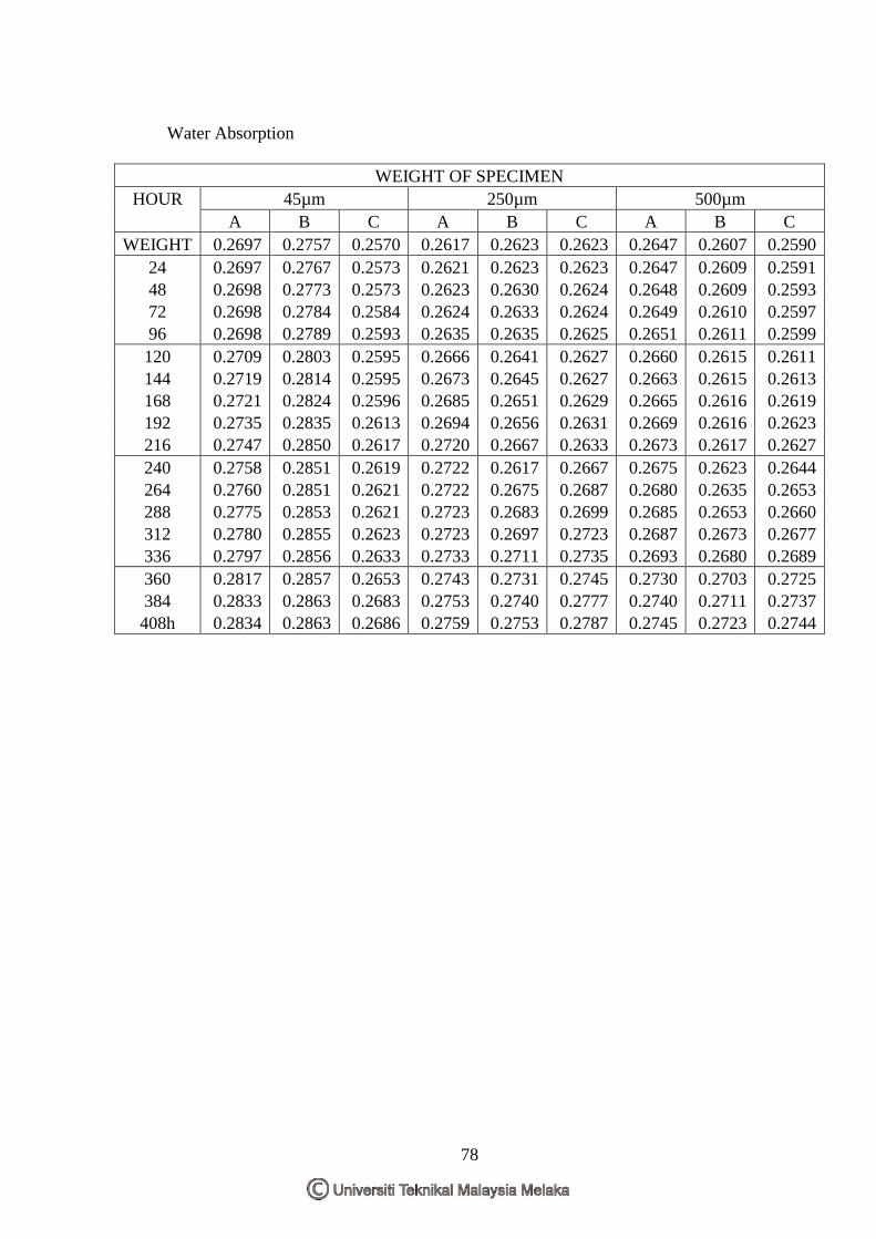
78
Water Absorption
WEIGHT OF SPECIMEN
HOUR 45µm 250µm 500µm
A B C A B C A B C
WEIGHT 0.2697 0.2757 0.2570 0.2617 0.2623 0.2623 0.2647 0.2607 0.2590
24 0.2697 0.2767 0.2573 0.2621 0.2623 0.2623 0.2647 0.2609 0.2591
48 0.2698 0.2773 0.2573 0.2623 0.2630 0.2624 0.2648 0.2609 0.2593
72 0.2698 0.2784 0.2584 0.2624 0.2633 0.2624 0.2649 0.2610 0.2597
96 0.2698 0.2789 0.2593 0.2635 0.2635 0.2625 0.2651 0.2611 0.2599
120 0.2709 0.2803 0.2595 0.2666 0.2641 0.2627 0.2660 0.2615 0.2611
144 0.2719 0.2814 0.2595 0.2673 0.2645 0.2627 0.2663 0.2615 0.2613
168 0.2721 0.2824 0.2596 0.2685 0.2651 0.2629 0.2665 0.2616 0.2619
192 0.2735 0.2835 0.2613 0.2694 0.2656 0.2631 0.2669 0.2616 0.2623
216 0.2747 0.2850 0.2617 0.2720 0.2667 0.2633 0.2673 0.2617 0.2627
240 0.2758 0.2851 0.2619 0.2722 0.2617 0.2667 0.2675 0.2623 0.2644
264 0.2760 0.2851 0.2621 0.2722 0.2675 0.2687 0.2680 0.2635 0.2653
288 0.2775 0.2853 0.2621 0.2723 0.2683 0.2699 0.2685 0.2653 0.2660
312 0.2780 0.2855 0.2623 0.2723 0.2697 0.2723 0.2687 0.2673 0.2677
336 0.2797 0.2856 0.2633 0.2733 0.2711 0.2735 0.2693 0.2680 0.2689
360 0.2817 0.2857 0.2653 0.2743 0.2731 0.2745 0.2730 0.2703 0.2725
384 0.2833 0.2863 0.2683 0.2753 0.2740 0.2777 0.2740 0.2711 0.2737
408h 0.2834 0.2863 0.2686 0.2759 0.2753 0.2787 0.2745 0.2723 0.2744
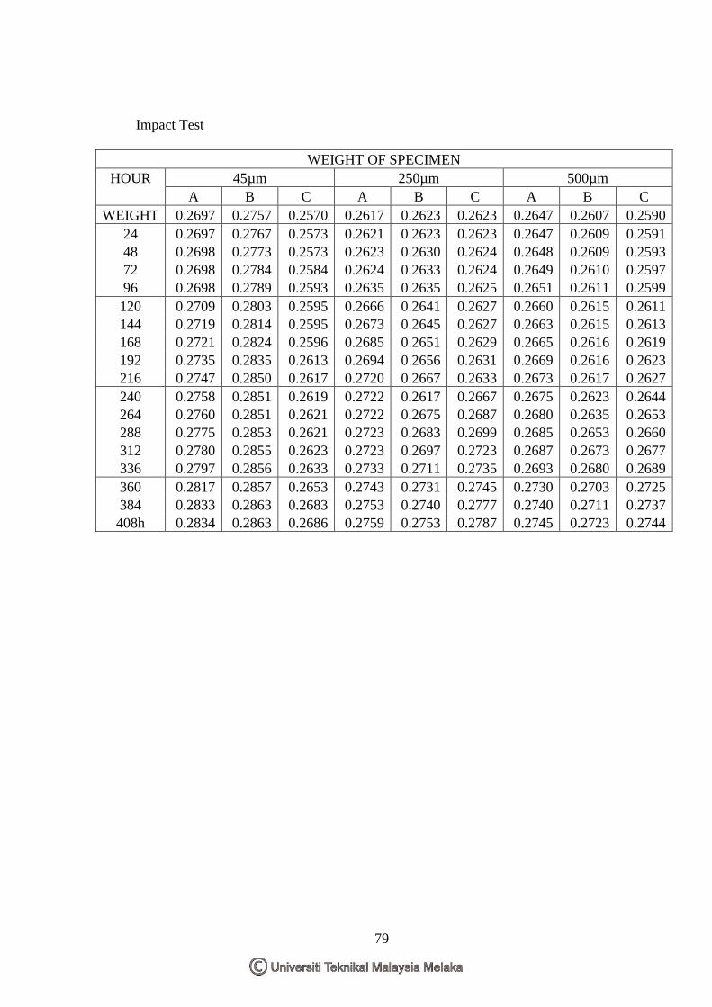
79
Impact Test
WEIGHT OF SPECIMEN
HOUR 45µm 250µm 500µm
A B C A B C A B C
WEIGHT 0.2697 0.2757 0.2570 0.2617 0.2623 0.2623 0.2647 0.2607 0.2590
24 0.2697 0.2767 0.2573 0.2621 0.2623 0.2623 0.2647 0.2609 0.2591
48 0.2698 0.2773 0.2573 0.2623 0.2630 0.2624 0.2648 0.2609 0.2593
72 0.2698 0.2784 0.2584 0.2624 0.2633 0.2624 0.2649 0.2610 0.2597
96 0.2698 0.2789 0.2593 0.2635 0.2635 0.2625 0.2651 0.2611 0.2599
120 0.2709 0.2803 0.2595 0.2666 0.2641 0.2627 0.2660 0.2615 0.2611
144 0.2719 0.2814 0.2595 0.2673 0.2645 0.2627 0.2663 0.2615 0.2613
168 0.2721 0.2824 0.2596 0.2685 0.2651 0.2629 0.2665 0.2616 0.2619
192 0.2735 0.2835 0.2613 0.2694 0.2656 0.2631 0.2669 0.2616 0.2623
216 0.2747 0.2850 0.2617 0.2720 0.2667 0.2633 0.2673 0.2617 0.2627
240 0.2758 0.2851 0.2619 0.2722 0.2617 0.2667 0.2675 0.2623 0.2644
264 0.2760 0.2851 0.2621 0.2722 0.2675 0.2687 0.2680 0.2635 0.2653
288 0.2775 0.2853 0.2621 0.2723 0.2683 0.2699 0.2685 0.2653 0.2660
312 0.2780 0.2855 0.2623 0.2723 0.2697 0.2723 0.2687 0.2673 0.2677
336 0.2797 0.2856 0.2633 0.2733 0.2711 0.2735 0.2693 0.2680 0.2689
360 0.2817 0.2857 0.2653 0.2743 0.2731 0.2745 0.2730 0.2703 0.2725
384 0.2833 0.2863 0.2683 0.2753 0.2740 0.2777 0.2740 0.2711 0.2737
408h 0.2834 0.2863 0.2686 0.2759 0.2753 0.2787 0.2745 0.2723 0.2744
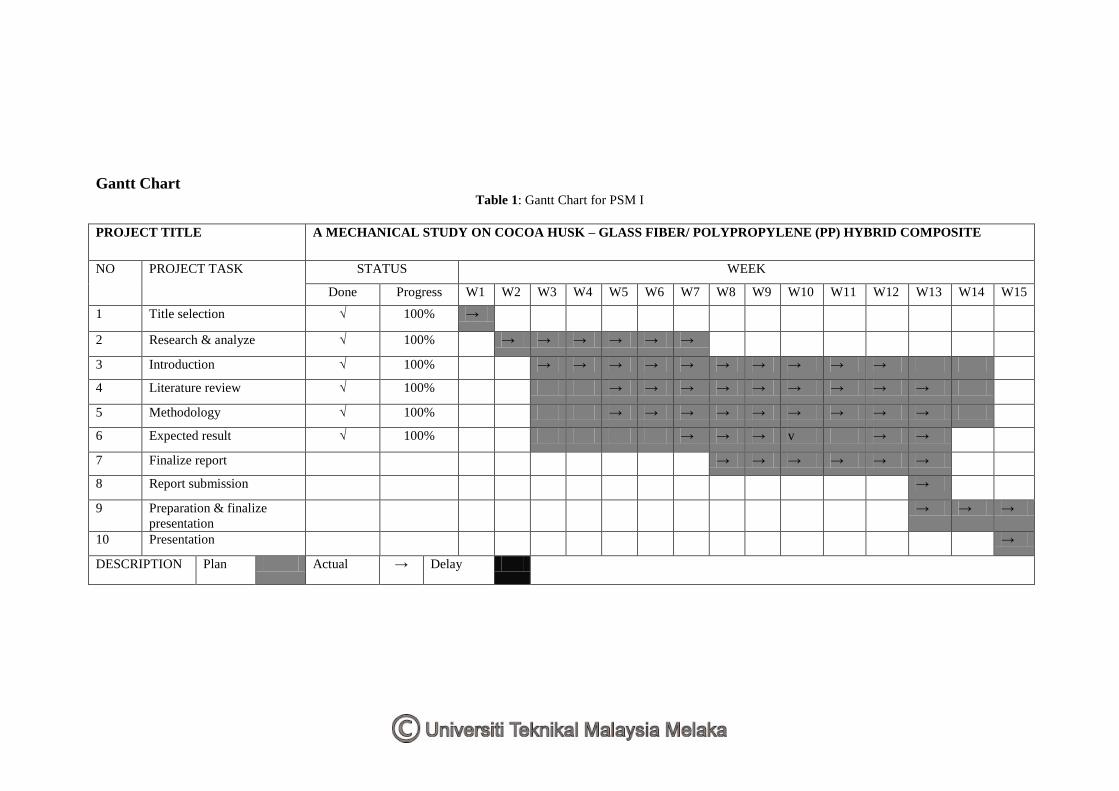
Gantt Chart Table 1: Gantt Chart for PSM I
PROJECT TITLE A MECHANICAL STUDY ON COCOA HUSK – GLASS FIBER/ POLYPROPYLENE (PP) HYBRID COMPOSITE
NO PROJECT TASK STATUS WEEK
Done Progress W1 W2 W3 W4 W5 W6 W7 W8 W9 W10 W11 W12 W13 W14 W15
1 Title selection √ 100% →
2 Research & analyze √ 100% → → → → → →
3 Introduction √ 100% → → → → → → → → → →
4 Literature review √ 100% → → → → → → → → →
5 Methodology √ 100% → → → → → → → → →
6 Expected result √ 100% → → → v → →
7 Finalize report → → → → → →
8 Report submission →
9 Preparation & finalize
presentation
→ → →
10 Presentation →
DESCRIPTION Plan Actual → Delay
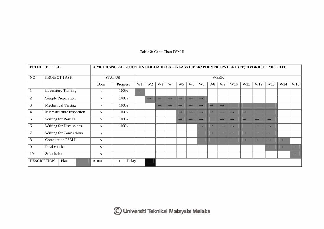
Table 2: Gantt Chart PSM II
PROJECT TITLE A MECHANICAL STUDY ON COCOA HUSK – GLASS FIBER/ POLYPROPYLENE (PP) HYBRID COMPOSITE
NO PROJECT TASK STATUS WEEK
Done Progress W1 W2 W3 W4 W5 W6 W7 W8 W9 W10 W11 W12 W13 W14 W15
1 Laboratory Training √ 100% →
2 Sample Preparation √ 100% → → → → → →
3 Mechanical Testing √ 100% → → → → → → →
4 Microstructure Inspection √ 100% → → → → → → →
5 Writing for Results √ 100% → → → → → → → →
6 Writing for Discussions √ 100% → → → → → →
7 Writing for Conclusions √ → → → → → →
8 Compilation PSM II √ → → → →
9 Final check √ → → →
10 Submission √ →
DESCRIPTION Plan Actual → Delay