the effect of plate geometry on flow and …eprints.utem.edu.my/16488/1/the effect of plate geometry...
TRANSCRIPT
THE EFFECT OF PLATE GEOMETRY ON FLOW AND HEAT TRANSFER
ACROSS A PARALLEL PLATE HEAT EXCHANGER
CHO WEI YANG
B041110217
Email: [email protected]
Projek Sarjana Muda
Supervisor: DR. FATIMAH AL-ZAHRAH BT. MOHD SA’AT
Faculty of Mechanical Engineering
Universiti Teknikal Malaysia Melaka
JUNE 2015
SUPERVISOR DECLARATION
“I hereby declare that I have read this thesis and in my opinion this thesis is
sufficient in terms of scope and quality for the award of the degree of
Bachelor of Mechanical Engineering (Automotive)”
Signature: ……………………………..
Supervisor: DR. FATIMAH AL-ZARAH BT. MOHD SA’AT
Date: …………………………….
THE EFFECT OF PLATE GEOMETRY ON FLOW AND HEAT TRANSFER ACROSS A PARALLEL PLATE HEAT EXCHANGER
CHO WEI YANG
This thesis is submitted as partial fulfilment of requirements for the award of Bachelor of Mechanical Engineering (Automotive) (Hons.)
Faculty of Mechanical Engineering Universiti Teknikal Malaysia Melaka
JUNE 2015
ii
DECLARATION
“I hereby declare that the work in this thesis is my own except for summaries and
quotations which have been duly acknowledged.”
Signature: ………………….
Author: CHO WEI YANG
Date: ………………….

iii
To my beloved father and mother
iv
ACKNOWLEDGEMENT
First and foremost, I would like to express my sincere gratitude to my supervisor,
Dr. Fatimah Al-Zahrah Mohd Sa’at, for guiding me throughout the entire PSM process.
Without the advices and help from her, carrying out this study would be almost
impossible. Therefore, I consider it as an honor to be able to work as a student under her.
I would also like to express my deepest gratitude to my university, Universiti
Teknikal Malaysia Melaka (UTeM), and my faculty, Faculty of Mechanical Engineering,
for granting me such great platform to learn and grow for the last four years.
Furthermore, I would like to thank all my friends who gave me support and
encouragement throughout my process of learning here in UTeM. Without them, I may
not be able to progress as smooth in my studies.
In addition, I would also like to take this opportunity to thank my parents and my
siblings in showering me with care and words of encouragement. Without them, I would
not be able to reach this stage. I am indebted to my family members for keep picking me
up when I fell down telling me not to give up.
v
ABSTRACT
When a flow is flowing past a blunt body or solid boundaries, there will be
formation of flow patterns and interactions between flow and the solid bodies. Other
than that, heat transfer can also take place if there is a temperature difference between
the flow and solid bodies. In this study, a pile of parallel-plates was considered as the
solid bodies. A simplified model of parallel-plate heat exchanger was chosen as the
computational domain in order to study of effect of plate geometry and channel
dimensions on the flow and heat transfer across a parallel-plate heat exchanger. There
will be an oscillatory flow where the flow moves back and forth across the solid
boundaries. The study was carried out using ANSYS software. Drawing of the
computational domain, meshing of the domain, solver settings and validation of the
model were carried out before the study can be recognized. After having done validation,
the results and data from the original model were compared with other three cases. One
of the three cases has round-shaped edges for its parallel-plates heat exchanger. The
remaining two cases have triangle-shaped edges with one having two times longer edge
length of the other one. All the cases were compared in terms of vorticity contours, total
and average surface heat flux and last but not least, velocity profile inside the channel.
The study shows that the shape of the edge affects the flow and the heat transfer of the
system. Vortices discontinuities were eliminated through the changing of edge shapes.
Heat energy transfer across the surface also changes when the shape of the edge changes.
vi
ABSTRAK
Apabila sesuatu aliran mengalir melepasi satu badan pepejal, akan berlakunya
pembentukan corak aliran dan interaksi antara aliran dan badan pepejal. Tambahan pula,
pemindahan haba juga boleh berlaku sekiranya terdapat perbezaan suhu antara aliran
dengan badan pepejal tersebut. Badan pepejal dalam kajian ini adalah timbunan plat
yang diaturkan secara selari. Satu model penukar haba plat-selari yang mudah dijadikan
sebagai domain untuk mengkaji tentang kesan penukaran geometri plat dan jarak antara
plat terhadap aliran dan juga pemindahan haba melalui penukar haba plat-selari. Aliran
berayun yang mana aliran tersebut akan beralir pergi dan balik akan dipilih sebagi jenis
aliran dalam kajian ini. Kajian ini dijalankan melalui penggunaan perisian ANSYS.
Lukisan domain, ‘meshing’ untuk domain, penetapan penyelesaian dan juga pengesahan
domain perlu dijalankan supaya kajian ini boleh diiktiraf. Setelah mengesah kesesuaian
model original, data model tersebut dibandingkan dengan tiga model yang lain. Salah
satu model mempunyai sisi yang bulat. Dua model mempunyai sisi segi tiga dan salah
satu mempunyai sisi yang dua kali lebih panjang daripada model yang satu lagi. Semua
model yang tersebut dibandingkan melalui kontur kepusaran, pemindahan tenaga haba
dan profil halaju dalam saluran. Kajian ini menunjukkan perubahan dari segi aliran dan
permindahan haba dalam sistem apabila bentuk sisi diubah.
vii
TABLE OF CONTENTS
CHAPTER TITLE PAGE
DECLARATION ii
ACKNOWLEDGEMENT iv
ABSTRACT v
ABSTRAK vi
TABLE OF CONTENTS vii
LIST OF FIGURES x
LIST OF TABLES xii
LIST OF ABBREVIATION AND SYMBOL xiii
LIST OF APPENDIXES xv
CHAPTER 1 INTRODUCTION
1.1 Background 1
1.2 Problem Statement 3
1.3 Motivation of Study 4
1.4 Objectives 4
1.5 Scope 4
CHAPTER 2 LITERATURE REVIEW
2.1 Flow 6
2.2 Heat Transfer 10
2.3 Heat Exchanger 12
2.4 Thermoacoustics 14
2.5 Working Principle of Thermoacoustic Device 15
viii
2.6 Effect of Geometry of Parallel-Plates on Flow
and Heat Transfer 17
CHAPTER 3 METHODOLOGY
3.1 Pre-Processing 22
3.2 Solver Settings 26
3.3 Pre-Processing for Different Geometries 30
CHAPTER 4 RESULTS AND ANALYSIS
4.1 Validation 32
4.2 Vorticity Contours 34
4.2.1 Original Model 35
4.2.2 Case 1 36
4.2.3 Case 2 37
4.2.4 Case 3 38
4.3 Total Surface Heat Flux 39
4.3.1 Original Model 40
4.3.2 Case 1 42
4.3.3 Case 2 43
4.3.4 Case 3 45
CHAPTER 5 DISCUSSION
5.1 Comparison of Local Surface Heat Flux
Between All the Cases at Point A 47
5.2 Comparison of Local Surface Heat Flux
Between All the Cases at Point B 48
5.3 Comparison of Local Surface Heat Flux
Between All the Cases at Point C 49
5.4 Comparison of Average Total Surface Heat
Flux Over Time at Hot Heat Exchangers
Between All Cases 50
ix
5.4 Vorticity Contours Comparison at the Edges
of All the Cases 51
5.5 Velocity Profile Comparison between All
the Cases 52
CHAPTER 6 CONCLUSION AND RECOMMENDATION 54
REFERENCES 55
APPENDIX A 58
x
LIST OF FIGURES
NO. TITLE PAGE
1.1 Illustration on position of heat exchangers and stack. 2
2.1 Illustration of laminar and turbulent flow. 7
2.2 Von Karman vortex (Cesareo de La Rosa Siqueira, 2005). 9
2.3 All three types of heat transfer process. 10
2.4 Illustration of double-pipe heat exchanger in parallel flow. 13
2.5 Illustration of double-pipe heat exchanger in cross flow. 13
2.6 PLIF image of heat transfer at the parallel-plates heat exchangers
from Jaworski and Piccolo (2012). 16
2.7 Illustration on the flow pattern at the end of sharp-edged plate. 20
2.8 Results from ANSYS Fluent 13 simulation on vortex generation
by Mohd Sa’at and Jaworski (2013). 21
3.1 Flow chart of this study. 22
3.2 Illustration of the computational domain and its dimensions. 23
3.3 Drawing of domain using ICEM. 24
3.4 Drawing of domain using ANSYS Workbench after creating surface. 25
3.5 Meshing of the domain after adjusting the sizing of the meshes. 25
3.6 FLUENT window. 26
3.7 Illustration of some important positions for calculation and validation
works. 28
3.8 Surface monitor setting changes for 1 cycle simulation. 29
3.9 Position of last point of curve after 1 cycle simulation. 29
3.10 Position of last point of curve for phase 0. 30
3.11 All simulation models with different geometries. 31
xi
4.1 Changes of x-velocity of point M at different phases. 32
4.2 Grid sensitivity test. 34
4.3 Vorticity contours of original model simulation at different phases. 35
4.4 Illustration of flow over original model from phase 0 to 10. 35
4.5 Illustration of flow over original model from phase 11 to 20. 36
4.6 Vorticity contours of case 1 model simulation at different phases. 36
4.7 Illustration of flow over case 1 model from phase 0 to 10. 37
4.8 Vorticity contours of case 2 model simulation at different phases. 37
4.9 Illustration of flow over case 2 model from phase 0 to 10. 38
4.10 Vorticity contours of case 3 model simulation at different phases. 38
4.11 Illustration of flow over case 3 model from phase 0 to 10. 39
4.12 Location of point A, B and C. 39
4.13 Local surface heat flux at point A, B and C for original model. 40
4.14 Average total surface heat flux at point A, B and C for original model. 41
4.15 Local surface heat flux at point A, B and C for case 1. 42
4.16 Average total surface heat flux at point A, B and C for case 1. 42
4.17 Local surface heat flux at point A, B and C for case 2. 43
4.18 Average total surface heat flux at point A, B and C for case 2. 44
4.19 Local surface heat flux at point A, B and C for case 3. 45
4.20 Average total surface heat flux at point A, B and C for case 3. 45
5.1 Local surface heat flux at point A for all the cases. 47
5.2 Local surface heat flux at point B for all the cases. 48
5.3 Local surface heat flux at point C for all the cases. 49
5.4 Average total surface heat flux at hot heat exchangers for all cases 50
5.5 Vorticity contours at the edges of all the models at phase 10. 51
5.6 Velocity profile for all the cases at phase 5. 52
5.7 Velocity profile for all the cases at phase 15. 53
xii
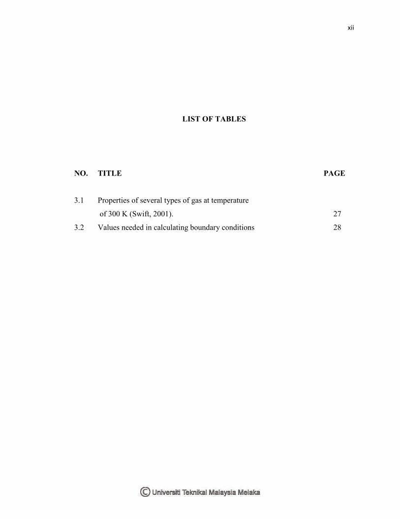
LIST OF TABLES
NO. TITLE PAGE
3.1 Properties of several types of gas at temperature
of 300 K (Swift, 2001). 27
3.2 Values needed in calculating boundary conditions 28
xiii
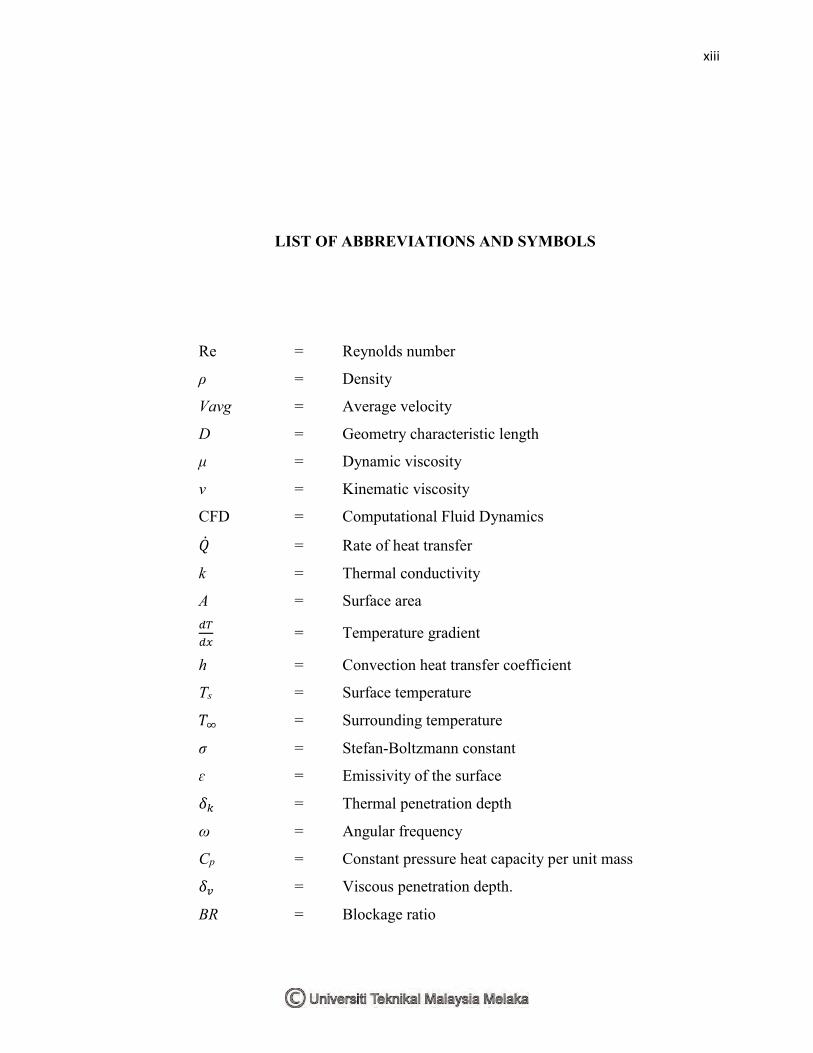
LIST OF ABBREVIATIONS AND SYMBOLS
Re = Reynolds number
ρ = Density
Vavg = Average velocity
D = Geometry characteristic length
μ = Dynamic viscosity
ν = Kinematic viscosity
CFD = Computational Fluid Dynamics
�̇� = Rate of heat transfer
k = Thermal conductivity
A = Surface area
𝑑𝑇
𝑑𝑥 = Temperature gradient
h = Convection heat transfer coefficient
Ts = Surface temperature
𝑇∞ = Surrounding temperature
σ = Stefan-Boltzmann constant
ɛ = Emissivity of the surface
𝛿𝑘 = Thermal penetration depth
ω = Angular frequency
Cp = Constant pressure heat capacity per unit mass
𝛿𝑣 = Viscous penetration depth.
BR = Blockage ratio
xiv
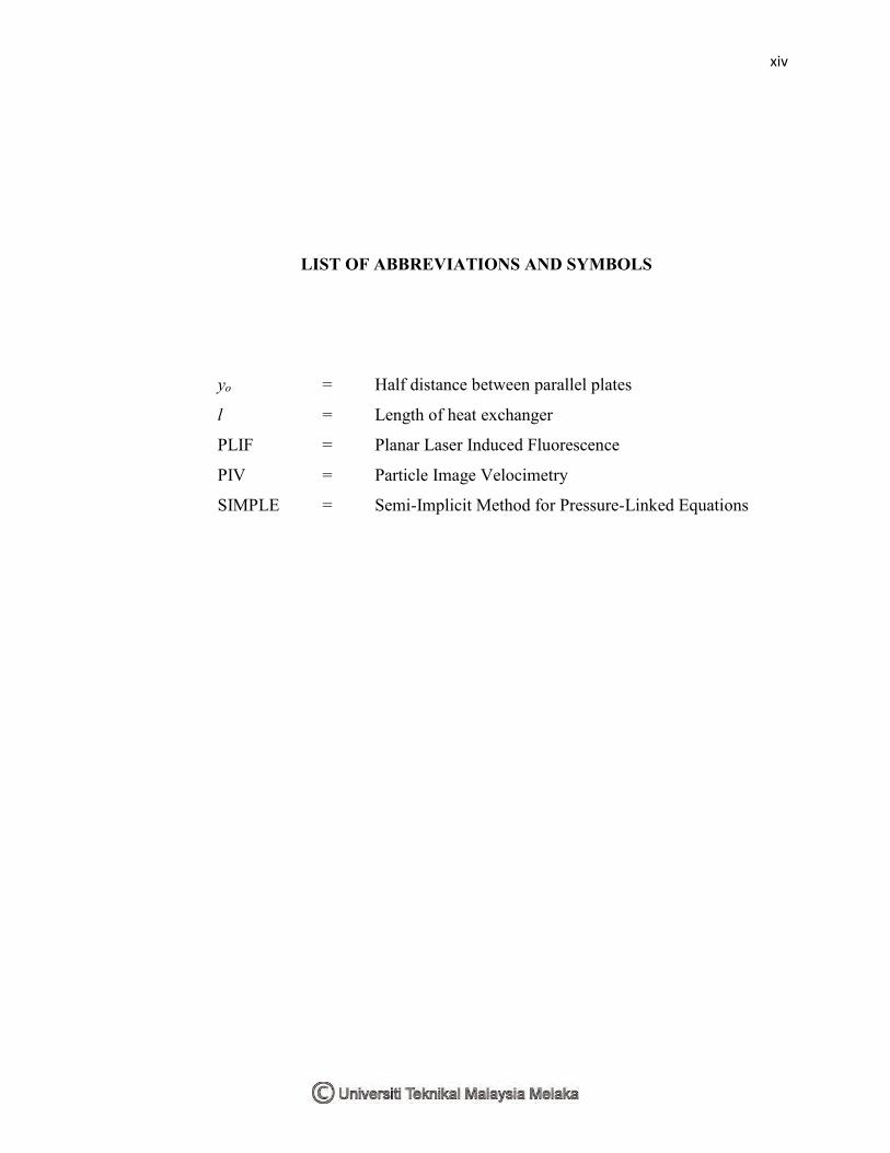
LIST OF ABBREVIATIONS AND SYMBOLS
yo = Half distance between parallel plates
l = Length of heat exchanger
PLIF = Planar Laser Induced Fluorescence
PIV = Particle Image Velocimetry
SIMPLE = Semi-Implicit Method for Pressure-Linked Equations
xv
LIST OF APPENDIXES
NO. TITLE PAGE
A Gantt Chart 58
1
CHAPTER 1
INTRODUCTION
1.1 BACKGROUND
When a flow is flowing past a blunt body or solid boundaries, there will be
interactions between the flow and the solid bodies. In this study, the solid boundaries will
be a pile of parallel-plates acting as heat exchangers. There will be formation of various
flow patterns when a flow flows past the parallel-plates. Other than flow patterns, there is
also interaction in terms of heat transfer since the parallel-plates will be acting as heat
exchangers. The temperature difference around the plates region will cause the occurrence
of heat transfer between the flow and the plates due to the temperature gradient. The focus
of this research is to study how the changes in the plate geometry (shape or dimensions of
parallel-plate) may disturb or affect the flow and heat transfer across a parallel-plate heat
exchanger. In discussing the flow and heat transfer across a parallel-plate heat exchanger,
the working medium used is very important too. Oscillatory flow which the flow will
propagate forth and back will be used in this research.
An example of application of oscillatory flow is as used in a reactor. Besides
thermoacoustics, this knowledge has been adapted into other technology such as
oscillatory flow reactor. Through different configurations of the reactor, it can serve
different purposes. The most common configuration is to operate as a mixer. Having an
oscillating flow can enhance the mixing as the mass and heat transfer rates are increased
2
significantly due to the back and forth movement. Oscillatory flow mixing technology can
also be found widely in chemical and process engineering. Another application of
oscillatory flow, which is also the focus of our research, is a thermoacoustic heat
exchanger. This heat exchanger extracts and supplies heat obtained from the
thermoacoustic system.
The main working medium behind thermoacoustics is a type of flow called
oscillatory flow. This flow is formed from sound waves with amplitudes high enough to
transfer heat from one place to another. On the other hand, sufficiently high temperature
gradient can also be used to create sound waves of high amplitudes. This flow plays an
important role because the oscillatory flow will move back and forth expanding and
contracting in order to do work.
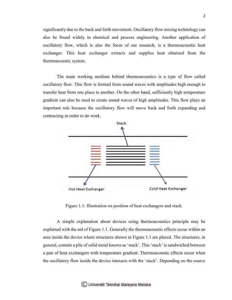
Figure 1.1: Illustration on position of heat exchangers and stack.
A simple explanation about devices using thermoacoustics principle may be
explained with the aid of Figure 1.1. Generally the thermoacoustic effects occur within an
area inside the device where structures shown in Figure 1.1 are placed. The structures, in
general, contain a pile of solid metal known as ‘stack’. This ‘stack’ is sandwiched between
a pair of heat exchangers with temperature gradient. Thermoacoustic effects occur when
the oscillatory flow inside the device interacts with the ‘stack’. Depending on the source
3
of energy, the interaction between the flowing fluid and the solid surface of the stack may
produce either cooling effect or power.
The heat exchangers at the ends of ‘stack’ are responsible to effectively remove
heat from the system and provide cooling capacity to the refrigerated space that is attached
to the system. On the other hand, if the heat exchangers provide a high enough temperature
gradient to the fluid, such that allows the fluid particle to excite, power will be produced.
The energy produced may then be harnessed for other useful application.
1.2 PROBLEM STATEMENT
The challenge in commercializing the thermoacoustic technologies lies, among
others, on understanding the behavior of the flow and heat transfer phenomena inside the
system. Current analytical solution used in designing the thermoacoustic system is based
on a one-dimensional linear model. However, in practical system, the flow may consist of
irregularities such as natural convection, streaming and vorticity. It is pertinent that these
effects are investigated so that a proper understanding may be gained. This involves the
fundamental knowledge of oscillatory flow. The study on heat transfer phenomenon in a
heat exchanger across oscillatory flow is important. There are many types of heat
exchanger and the parallel-plate heat exchanger is one of them. As the geometry of the
parallel-plates structure is changed, the flow properties near the plates will also change.
This may somehow affect the interactions between the oscillatory flow and the solid
surfaces. The changing of geometry may also create disturbances or other effects on the
flow. The usual shape of the plates is rectangle with sharp edges. It will be interesting to
study what changes may be observed if the shape of the plates is changed for example, to
round edges or to other shapes.
4
1.3 MOTIVATION OF STUDY
Often the other parameters are taken into consideration when studies are carried
out regarding the oscillatory flow or heat transfer near solid structures. Geometry and gap
dimensions however get less attention as compared to other parameters. Considering the
fact that changing geometry will affect the contact surface of the plate and also the
possibility of creating disturbances to the flow, researches should be carried out more
about this factor. The purpose of this study is to gain more information on the effect of
geometry of the parallel-plates on the heat transfer and flow so that this concept appears
attractive to the industry sooner.
1.4 OBJECTIVES
There are several objectives in completing the study. The objectives are to:
i) Study the thermoacoustic heat exchanger and to understand the working
principle and knowledge related to it.
ii) Formulate simplified models for the purpose of comparison of flow and heat
transfer between different geometries.
iii) Validate the model with available published work; experimental or theoretical
data.
iv) Analyze the results and study the effect of parallel-plates geometry on the flow
and heat transfer around the heat exchanger.
1.5 SCOPE
There are several parameters that can be manipulated in order to study the factors
affecting the flow and heat transfer such as the mean pressure, velocity amplitude,
frequency and also phase difference. However in this study, the focus will only be on the
effect of geometry of the parallel plates on the flow behavior of the system. This involves

5
several different shape of the edge of the heat exchanger plates. The parallel plates in this
research will be used to represent the heat exchangers used in real thermoacoustic devices.
This research will cover only the oscillatory flow encountered in a thermoacoustic system.
A simplified model of parallel plates will be formulated for the research.
6
CHAPTER 2
LITERATURE REVIEW
2.1 FLOW
Over the years, numerous researches had been carried out in the field of
thermoacoustics. In thermoacoustic applications, fluid may be considered as the working
medium. One important aspect that needs to be understood is the flow of the fluid. Flow
is the propagation of fluid from one place to another along a stream. There are three phases
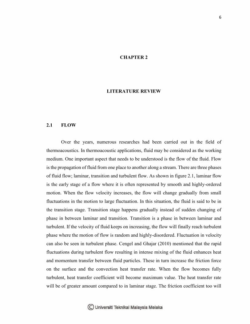
of fluid flow; laminar, transition and turbulent flow. As shown in figure 2.1, laminar flow
is the early stage of a flow where it is often represented by smooth and highly-ordered
motion. When the flow velocity increases, the flow will change gradually from small
fluctuations in the motion to large fluctuation. In this situation, the fluid is said to be in
the transition stage. Transition stage happens gradually instead of sudden changing of
phase in between laminar and transition. Transition is a phase in between laminar and
turbulent. If the velocity of fluid keeps on increasing, the flow will finally reach turbulent
phase where the motion of flow is random and highly-disordered. Fluctuation in velocity
can also be seen in turbulent phase. Cengel and Ghajar (2010) mentioned that the rapid
fluctuations during turbulent flow resulting in intense mixing of the fluid enhances heat
and momentum transfer between fluid particles. These in turn increase the friction force
on the surface and the convection heat transfer rate. When the flow becomes fully
turbulent, heat transfer coefficient will become maximum value. The heat transfer rate
will be of greater amount compared to in laminar stage. The friction coefficient too will
7
become maximum when the flow is fully turbulent. This will requires more input to
overcome the large friction forces.
Figure 2.1: Illustration of laminar and turbulent flow.
The classification of the three phases mentioned earlier is made possible with the
help of a dimensionless number, the Reynolds number. Reynolds numbers, Re, was
discovered by Osborne Reynolds in 1880s. He found out that the flow regime or the order
of the flow is highly dependent on the ratio of inertial forces to viscous forces in the fluid.
Inertial force can be considered as the amount of force a fluid put up to resist any change
in its motion. Viscous force can be explained as the shear force experienced by the flow
when it flows past a solid body. In easier analogue, viscous force can be considered as
frictional force. Reynolds number can be expressed as;
Re = inertial forces
viscous forces = 𝜌𝑉𝑎𝑣𝑔𝐷
𝜇 (2.1)
where ρ is the density of medium, Vavg is the average velocity of the flow, D is the
geometry characteristic length and μ is the dynamic viscosity of the medium. Reynolds
number can also be expressed in terms of kinematic viscosity;
Re = 𝑉𝑎𝑣𝑔𝐷
𝜈 (2.2)