sub-surface flow and free water surface flow … · flow constructed wetland with magnetic field...
TRANSCRIPT

SUBSURFACE FLOW AND FREE WATER SURFACE FLOW CONSTRUCTED
WETLAND WITH MAGNETIC FIELD FOR LEACHATE TREATMENT
SITI KAMARIAH BINTI MD SA’AT
UNIVERSITI TEKNOLOGI MALAYSIA

PSZ 19:16 (Pind. 1/97)
UNIVERSITI TEKNOLOGI MALAYSIA
CATATAN: * Potong yang tidak berkenaan. ** Jika tesis ini SULIT atau TERHAD, sila lampirkan surat daripada pihak berkuasa/organisasi
BORANG PENGESAHAN STATUS TESISυ
JUDUL: SUBSURFACE FLOW AND FREE WATER SURFACE FLOW .
CONSTRUCTED WETLAND WITH MAGNETIC FIELD FOR LEACHATE
TREATMENT .
SESI PENGAJIAN: 2006/2007
Saya SITI KAMARIAH BINTI MD SA’AT
(HURUF BESAR) mengaku membenarkan tesis (PSM/Sarjana/Doktor Falsafah)* ini disimpan di Perpustakaan Universiti Teknologi Malaysia dengan syarat-syarat kegunaan seperti berikut: 1. Tesis adalah hakmilik Universiti Teknologi Malaysia. 2. Perpustakaan Universiti Teknologi Malaysia dibenarkan membuat salinan untuk tujuan
pengajian sahaja. 3. Perpustakaan dibenarkan membuat salinan tesis ini sebagai bahan pertukaran antara
institusi pengajian tinggi. 4. **Sila tandakan ( √ )
SULIT (Mengandungi maklumat yang berdarjah keselamatan atau kepentingan Malaysia seperti yang termaktub di dalam
AKTA RAHSIA RASMI 1972)
TERHAD (Mengandungi maklumat TERHAD yang telah ditentukan oleh organisasi/badan di mana penyelidikan dijalankan)
√ TIDAK TERHAD
__________________________________
(TANDATANGAN PENULIS)
Disahkan oleh
_____________________________________
(TANDATANGAN PENYELIA)
Alamat Tetap:
NO 11, JALAN GEMILANG 4,
TAMAN UPC, AYER HITAM,
86100 JOHOR DARUL TAKZIM
DR JOHAN SOHAILI
Nama Penyelia
Tarikh: 15 NOVEMBER 2006 Tarikh: 15 NOVEMBER 2006
berkenaan dengan menyatakan sekali sebab dan tempoh tesis ini perlu dikelaskan sebagai SULIT atau TERHAD.
υ Tesis dimaksudkan sebagai tesis bagi Ijazah Doktor Falsafah dan Sarjana secara penyelidikan, atau disertasi bagi pengajian secara kerja kursus dan penyelidikan, atau Laporan Projek Sarjana Muda (PSM).

“I hereby declare that I have read this project report and in my opinion this
project report is sufficient in term of scope and quality for the award of the
degree of Master of Engineering (Civil- Wastewater)”
Signature :…………………..
Name of Supervisor : Dr. Johan Sohaili
Date : 15 November 2006
SUBSURFACE FLOW AND FREE WATER SURFACE FLOW CONSTRUCTED
WETLAND WITH MAGNETIC FIELD FOR LEACHATE TREATMENT
SITI KAMARIAH BINTI MD SA’AT
A project report submitted in fulfilment of the
requirement of the award of the degree of
Master of Engineering (Civil-Wastewater)
Faculty of Civil Engineering
Universiti Teknologi Malaysia
NOVEMBER 2006
ii
I declare that this project report entitled “Subsurface flow and Free Water Surface
Flow Constructed Wetland with Magnetic Field for Leachate Treatment” is the result
of my own research except as cited in the references. The project report has not been
accepted for any degree and is not concurrently submitted in candidature of any other
degree.
Signature : ………………………………………
Name : SITI KAMARIAH BINTI MD SA’AT
Date : 15 NOVEMBER 2006

iii
To my mother, father, my lovely sisters
Angah, Obi, Gina, Ida, Arfah and Adik

iv
ACKNOWLEDGEMENT
Alhamdulillah, grateful to Allah s.w.t., to give me the opportunity to complete my
project report.
Firstly, I would like to express my appreciation to my supervisor, Dr. Johan
Sohaili for his guidance and supervision over the period of this project. I really
appreciate the effort and time he had spent which eventually enabled me to complete
my project report.
Next, I am also thankful to all the technicians of Environmental Engineering
Laboratory, Pak Usop, En. Mus, Kak Ros, En. Ramlee Ismail and En. Ramli Aris for
their help, guidance and cooperations through all my laboratory startup and
difficulties in experimental works.
Finally, my sincere appreciation also extends to all my colleagues and others
who have provided assistance at various occasions especially to Ain Nihla, Shila and
Nadiah. I am also grateful to all my family members. I would like to thank my
dearest family, sisters, and my beloved, to whom I dedicated this dissertation. They
always have been behind me with love, support and endless patient.
Thank you.
v
ABSTRACT
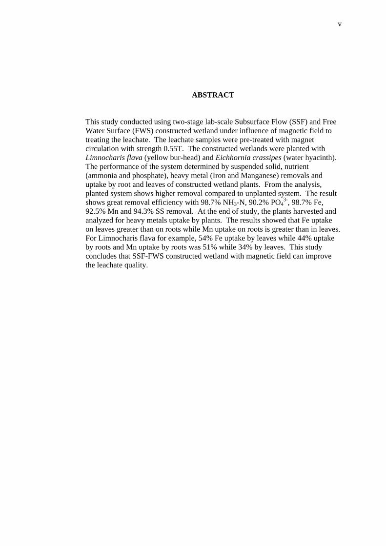
This study conducted using two-stage lab-scale Subsurface Flow (SSF) and Free Water Surface (FWS) constructed wetland under influence of magnetic field to treating the leachate. The leachate samples were pre-treated with magnet circulation with strength 0.55T. The constructed wetlands were planted with Limnocharis flava (yellow bur-head) and Eichhornia crassipes (water hyacinth). The performance of the system determined by suspended solid, nutrient (ammonia and phosphate), heavy metal (Iron and Manganese) removals and uptake by root and leaves of constructed wetland plants. From the analysis, planted system shows higher removal compared to unplanted system. The result shows great removal efficiency with 98.7% NH3-N, 90.2% PO4
3-, 98.7% Fe, 92.5% Mn and 94.3% SS removal. At the end of study, the plants harvested and analyzed for heavy metals uptake by plants. The results showed that Fe uptake on leaves greater than on roots while Mn uptake on roots is greater than in leaves. For Limnocharis flava for example, 54% Fe uptake by leaves while 44% uptake by roots and Mn uptake by roots was 51% while 34% by leaves. This study concludes that SSF-FWS constructed wetland with magnetic field can improve the leachate quality.
vi
ABSTRAK
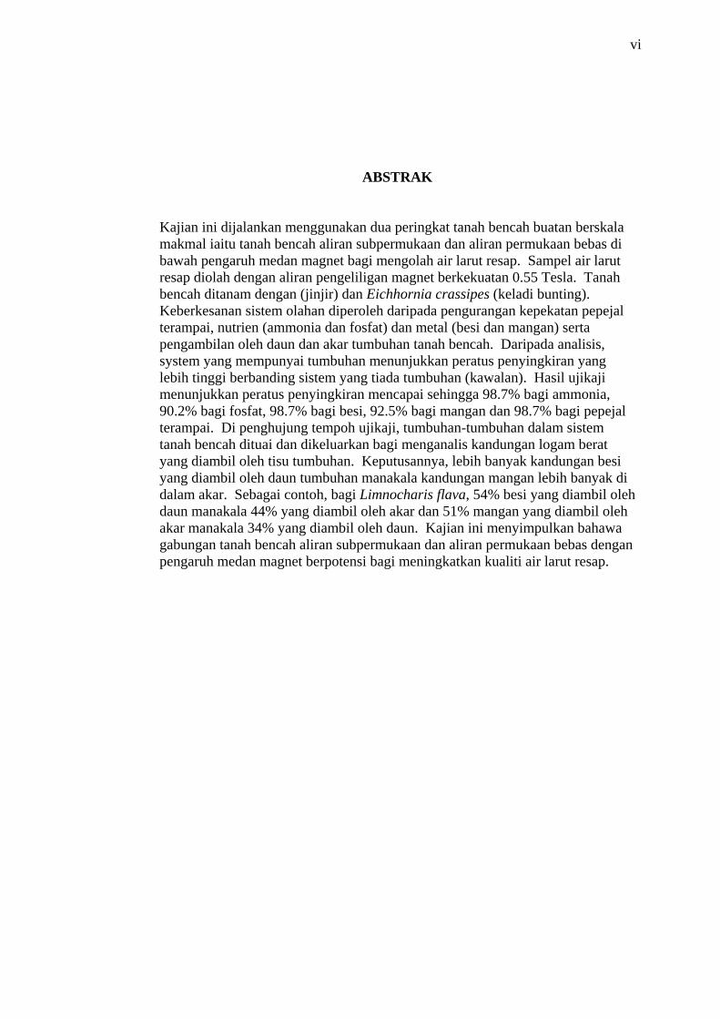
Kajian ini dijalankan menggunakan dua peringkat tanah bencah buatan berskala makmal iaitu tanah bencah aliran subpermukaan dan aliran permukaan bebas di bawah pengaruh medan magnet bagi mengolah air larut resap. Sampel air larut resap diolah dengan aliran pengeliligan magnet berkekuatan 0.55 Tesla. Tanah bencah ditanam dengan (jinjir) dan Eichhornia crassipes (keladi bunting). Keberkesanan sistem olahan diperoleh daripada pengurangan kepekatan pepejal terampai, nutrien (ammonia dan fosfat) dan metal (besi dan mangan) serta pengambilan oleh daun dan akar tumbuhan tanah bencah. Daripada analisis, system yang mempunyai tumbuhan menunjukkan peratus penyingkiran yang lebih tinggi berbanding sistem yang tiada tumbuhan (kawalan). Hasil ujikaji menunjukkan peratus penyingkiran mencapai sehingga 98.7% bagi ammonia, 90.2% bagi fosfat, 98.7% bagi besi, 92.5% bagi mangan dan 98.7% bagi pepejal terampai. Di penghujung tempoh ujikaji, tumbuhan-tumbuhan dalam sistem tanah bencah dituai dan dikeluarkan bagi menganalis kandungan logam berat yang diambil oleh tisu tumbuhan. Keputusannya, lebih banyak kandungan besi yang diambil oleh daun tumbuhan manakala kandungan mangan lebih banyak di dalam akar. Sebagai contoh, bagi Limnocharis flava, 54% besi yang diambil oleh daun manakala 44% yang diambil oleh akar dan 51% mangan yang diambil oleh akar manakala 34% yang diambil oleh daun. Kajian ini menyimpulkan bahawa gabungan tanah bencah aliran subpermukaan dan aliran permukaan bebas dengan pengaruh medan magnet berpotensi bagi meningkatkan kualiti air larut resap.

vii
TABLE OF CONTENTS
CHAPTER SUBJECT PAGE
TITLE
DECLARATION
DEDICATION
ACKNOWLEDGEMENT
ABSTRACT
TABLE OF CONTENT
LIST OF TABLES
LIST OF FIGURES
LIST OF SYMBOLS
LIST OF APPENDIX
i
ii
iii
iv
v
vii
x
xii
xiv
xv
1 INTRODUCTION
1.1 Introduction
1.2 Problem Background
1.3 Objectives
1.4 Scope of study
1.5 Significant of study
1
2
3
4
4
2 LITERATURE REVIEW
2.1 Introduction
2.2 Landfill Leachate
2.2.1 Leachate Formation Mechanism
2.2.2 Composition of Leachate
2.2.3 Leachate Treatment Method
6
6
7
10
12
viii
2.3 Constructed Wetland
2.3.1 Types of Constructed Wetlands
2.3.2 Wetland Plants
2.3.3 Mechanism of Treatment Processes in
Contaminant Removal
2.3.4 Summary of Treatment Performance of
Constructed Wetland
2.4 Magnetic field
2.4.1 Lorentz Force
2.4.2 Variation
2.4.3 Magnetic Memory
2.4.4 Magnetic Treatment System
2.4.5 Magnetic Field For Water Treatment
2.4.6 Magnetic Field for Wastewater
Treatment
2.5 Conclusion
16
16
18
22
26
28
31
33
35
35
37
38
39
3 METHODOLOGY
3.1 Introduction
3.2 Experimental Setup
3.3 Wetland Plants
3.4 Media
3.5 Sampling and Analysis
3.6 Heavy Metal Uptake by Plants
42
42
46
47
48
48
4 RESULT AND DISCUSSION
4.1. Introduction
4.2. Nutrient Removal
4.2.1. Ammonia Nitrogen Removal
4.2.2. Nitrate Nitrogen Removal
4.2.3. Orthophosphate Removal
4.3. Heavy Metal Removal
4.3.1. Iron Removal
50
52
53
57
58
61
62
ix
4.3.2. Manganese Removal
4.4. Suspended Solid Removal
4.5. Heavy Metal Uptake by Plants
4.6. Conclusion
64
66
69
71
5 CONCLUSION AND RECOMMENDATION
5.1. Conclusion
5.2. Recommendation and Suggestion
73
74
REFERENCES
APPENDICES
Appendix A- Data Obtain From Experiment
Appendix B- Performance and Removal Efficiency
Appendix C- Analysis of Variance (ANOVA)
75
88
x
LIST OF TABLES
TABLE NO. TITLE PAGE
2.1
2.2
2.3
2.4
2.5
2.6
3.1
3.2
4.1
4.2
4.3
4.4
4.5
4.6
Typical data on the composition of leachate from
new and mature landfill
Physical, Chemical and Biological Treatment
Processes for Leachate Treatment
Roles of vegetations in constructed wetlands
Overview of Pollutant Removal Process
Summary of constructed wetland studies on
wastewater
Summary of constructed wetland studies on landfill
leachate
Characteristics of Eichhornia crassipes
Characteristics of Limnocharis flava
Initial quality of leachate
The comparison of removal efficiency between
planted and control constructed wetland system after
21 days of treatment
Correlation between removal efficiency with time of
treatment for NH3-N
Correlation between removal efficiency with time of
treatment for PO43- removal
Correlation for Fe removal with time for control and
planted constructed wetland
Correlation for Mn removal with time for control and
planted constructed wetland
11
14
19
22
27
28
46
47
51
52
54
59
63
64

xi
4.7
Correlation between SS removal efficiency and time
for control and planted constructed wetland
67
xii
LIST OF FIGURES
FIGURE NO. TITLE PAGE
2.1
2.2
2.3
2.4
2.5
2.6
2.7
2.8
2.9
2.10
2.11
2.12
3.1
3.2
3.3
3.4
4.1
Factors influencing leachate formation in landfills
Typical Landfill Leachate Chracteristics Over Time
Type of constructed wetland
Types of Wetland Plants
Major pollutant uptake and release pathways in a
wetlands system
Processes of metals removal in constructed wetlands
Magnetic field lines or magnetic flux
Molecules Arrangement with and without magnetic
field in water
The ion charge particle (a) in uniform charge density,
(b) ion become distort due to external electric filed
with positive and negative charge in opposite position
Forces affecting the particle when magnetic field is
applied in perpendicular direction
Illustration of classes of magnetic devices by
installation location
Classification of permanent magnet type
Experimental Setup
Photograph of the experimental setup
Arrangement of magnet set
HACH DR 4000 Spectrophotometer
Removal efficiency of NH3-N in control and planted
constructed wetland system with magnetic field
8
9
17
20
23
26
29
30
31
32
33
34
43
44
45
49
54
xiii
4.2
4.3
4.4
4.5
4.6
4.7
4.8
4.9
4.10
4.11
4.12
4.13
Comparison a performance between control and
planted constructed wetland in NH3-N removal
Removal efficiency for NO3-N comparison between
control and planted constructed wetland with
magnetic field
Removal Efficiency of PO43- for control and planted
constructed wetland with magnetic field
PO43- removal performance in planted and control
constructed wetland
Removal Efficiency of Fe in control and planted
constructed wetland with magnetic field
Iron removal performance in control and planted
system
Removal Efficiency of Mn in control and planted
constructed wetland with magnetic field
Manganese removal performance in control and
planted system
Removal Efficiency of Suspended Solid in control
and planted constructed wetland with magnetic field
SS removal performance in control and planted
constructed wetland
Fe concentration in initial and in the end of
experiment for both plants
Mn concentration in initial and in the end of
experiment for both plants
55
58
59
60
62
63
64
65
67
68
70
70

xiv
LIST OF SYMBOLS
BOD - Biochemical Oxygen Demand
COD - Chemical Oxygen Demand
C/Co - Present concentration over initial concentration
Fe - Iron
FWS - Free water surface flow
k - Removal rate constant
mg/L - milligram per liter
Mn - Manganese
NH3-N - Ammonia Nitrogen
NO3-N - Nitrate Nitrogen
PO43- - Orthophosphate
Q - Flowrate
r2 - Correlation coefficient
SS - Suspended Solid
SSF - Subsurface flow
t - time
T - Tesla

xv
LIST OF APPENDICES
APPENDIX TITLE PAGE
A Data Obtain From Experiment
89
B Performance and Removal Efficiency
93
C Analysis of Variance (ANOVA)
97
CHAPTER 1
INTRODUCTION
1.1 Introduction
Over the years, industrialization and urbanization with the high growth rate
has causes several environmental problem all over the world. Nowadays, solid waste
management and wastewater treatment are most important problems that we are
facing. Malaysia, like most of the developing countries, is facing an increase of the
generation of waste and of accompanying problems with the disposal of this waste.
The amount of solid wastes produced around the world is increasing at high rates.
Landfill is one of the most widely employed methods for the disposal of municipal
solid waste (MSW). Up to 95% total MSW collected worldwide is disposed of in
landfills (El-Fadil et al, 1997). However the landfill causes generation of leachate.
Landfill leachates will cause environmental problems without proper handling.
Increase in landfill leachate creates challenges for cost effective treatment methods to
process wastewater.
In recent years, natural treatment systems, including wetlands have grown in
popularity for wastewater treatment since the early 1980s (Reed et al., 1995).
Constructed wetland is a most promising method to treating landfill leahate. The
potential to expand the use of constructed wetlands to the treatment of landfill
leachates is relevant to today context because it seem to be environmental sustainable
for the treatments of many constituent and cost savings. At present, there are several
constructed wetland facilities in operation around the world. Constructed wetlands
2
are preferred because they have more engineered systems and they are easier to
control.
Magnetic treatment attracts a special attention due to its safety, purity,
simplicity and low operating costs. There are only few studies that use magnetic
field for wastewater treatment processes, and in most of them, magnetic field is used
only for separation of solids or attached microorganisms from effluent. The
magnetic field tended to increase the bacterial activity and able to detoxify toxic
compounds (Yavus and Celebi, 2000). It also tended to increase sedimentation of
suspended solid in wastewater (Johan, 2003). Since lack of studies of magnetic field
potential in wastewater treatment, this study will investigate the performance of
magnetic field in leachate treatment with combination of constructed wetlands
system Subsurface Flow (SSF) and Free Water Surface (FWS).
1.2 Problem Background
Landfill leachate is wastewater emanated from sanitary landfills treating a
variety of municipal and industrial solid wastes. Due to anaerobic conditions and
long retention time prevailing in sanitary landfills, landfill leachate normally contains
high concentrations of organic matters, nutrients, pathogens and heavy metals which,
if not properly collected and treated, can cause serious pollution to nearby surface
and groundwater sources. Organic matter in leachate can cause decomposition by
microorganisms and can cause oxygen depletion in surface water bodies. The
presence of heavy metals such as mercury, iron, manganese and copper at high
concentrations in landfill leachate usually causes toxic effects to microbes, making it
difficult to be treated biologically. Landfill leachate may contaminate not only
surface water and groundwater supplies (Tatsi and Zouboulis, 2002) but may also
cause marine water pollution and trans-boundary contamination (Al-Muzaini et al.,
1995).
Leachate treatment has become an important issue due to the contamination
of water resources. There are various options to treat landfill leachates. The
3
identification of the preferred option in specific circumstance is a function of the
cost; both operating and capital cost and the limitation impose on the quality and
quantity of discharge. The potential methods for the management of landfill
leachates are mainly recirculation of leachate through the landfill, physical-chemical
treatment, membrane filtration and reverse osmosis, anaerobic and aerobic biological
treatment and constructed wetlands (Kappelmeyer, 2005).
Locally, many studies have been conducted for leachate treatment using
constructed wetlands (Aeslina, 2003, Lee, 2003, Thien, 2006). Nevertheless, this
technology is less utilized in Malaysia. Field and laboratory studies that have been
conducting using wetland systems to treat leachate show variable results (Surface et
al., 1993; Mulamoottil et al., 1998, Liehr et al., 2000 and Cossu et al, 2001).
Inconsistent results can be attributed to the variable nature of the leachate and the
lack of universally accepted design standards for wetland treatment systems.
1.3 Objective
In this study, the application of constructed wetland to treating landfill
leachate is applying under influence of magnetic field effect. The objectives of this
study are:
(i) To investigate a performance of SSF-FWS constructed wetland under
influence of magnetic field;
(ii) To examine the effect of SSF and FWS plant on leachate quality for
suspended solid (SS), nutrient (NH3-N, NO3-N and PO43-) and heavy
metal (Fe and Mn) removal and;
(iii) To examine the amount of heavy metal uptake by root and leaves of the
SSF and FWS plant.
4
1.4 Scopes of Study
The scopes of this study are includes: set-up two stage constructed wetland
(SSF-FWS) to treating landfill leachate under influence of magnetic field. The
experiments are carried out in the Environmental Laboratory, Faculty of Civil
Engineering, Universiti Teknologi Malaysia. Leachate sample is taken from Pasir
Gudang Sanitary Landfill. The plants use in this study are Eichhornia crassipes
(water hyacinth) as floating plant for FWS wetland and Limnocharis flava (yellow
bur-head) as plant for SSF wetland. Six set of permanent magnet used in this study
with magnetic strength of 0.55 T. The performance of magnetic field in constructed
wetland evaluates using water quality parameter suspended solid (SS), ammonia
nitrogen (NH3-N), nitrate nitrogen (NO3-N) and orthophosphate (PO43-) and heavy
metals (iron, Fe and manganese, Mn) removal. The heavy metal uptake by plants
also investigate by analyze the plant roots and leaves.
1.5 Significant of the study
The study is conducted to evaluate the performance of magnetic field in
combined constructed wetland to treating landfill leachate. It also an environmental
friendly approach. Leachate poses a number of environmental problems. This is due
to variable types of waste and its composition. Leachate can contain high
concentration of organic matters, nutrients and heavy metals. In the recent years the
interest is more on natural system treatment. In this way, constructed wetlands
represent a viable choice, offering extremely positive characteristics for treatment of
the landfill leachate, as a good removal of heavy metals; great capacity of nitrifying-
denitrifying, with consequent lowering of high concentrations of ammonia typical of
landfill leachate; sensible reduction of the volume of the leachate, due to high
evapotranspiration bring by plants, and consequently sensible reduction of the costs
of an eventual further treatment of the leachate. According to Eckhardt et al.,
(1999), combination of constructed wetland (FWS and SSF) has potential to increase
removal of pollutant from landfill leachate. It is shows high removal of BOD,

5
phosphorus and heavy metals. Thus, the study of combined constructed wetland
investigated because it has not been discovered yet in Malaysia.
Magnetic field proven has potential in wastewater treatment. Although,
magnetic technology uses is still new in Malaysia. According studied by Johan,
(2003) higher magnetic strength will enhance the settling of suspended particles and
reduction of SS, BOD5, NH3-N and COD concentration in wastewater. Magnetic
field can affect the equilibrium and stabilization of suspended particles to settle after
aggregation process. Therefore, the carry out study on combination of constructed
wetland and magnetic field will be the promising method to treat the leachate with
proper treatment and low cost.
CHAPTER 2
LITERATURE REVIEW
2.1 Introduction
This chapter includes literature review on landfill leachate, constructed
wetland and magnetic field that related to the scope of the study. Landfill leachate
has become highly contaminated due to the high population growth rate,
industrialization and urbanization. As leachate migrates away from a landfill, it may
cause serious pollution to the adjacent surface waters as well as groundwater.
Constructed wetland combined with magnetic field has become the promising
method to treat a landfill leachate
2.2 Landfill Leachate
Landfill leachate is wastewater emanated from sanitary landfills treating a
variety of municipal and industrial solid wastes. Most organic matter contained in
the solid wastes is biodegradable and can be broken down into simpler compounds
by anaerobic and aerobic microorganisms, leading to the formation of leachate. Due
to anaerobic conditions and long retention time prevailing in sanitary landfills,
landfill leachate normally contains high concentrations of organic matters, nutrients,
pathogens and heavy metals which, if not properly collected and treated, can cause
serious pollution to nearby surface and groundwater sources. The presence of heavy
7
metals at high concentrations in landfill leachate usually causes toxic effects to
microbes, making it difficult to be treated biologically.
The leachates may migrate from the refuse and contaminate the surface
waters and groundwater, affecting aquatic ecosystems and human health. In most
landfills leachate is composed of the liquid that has entered the landfill from external
sources, such as surface drainage, rainfall, groundwater and water from underground
and the liquid produced from the decomposition of the wastes (Tchobanouglous et
al., 1993). The characteristics and flow of landfill leachates depend of the
composition of solid wastes, precipitation, runoff, age of the landfill and
permeability and type of cover. Solid waste composition varies substantially with
socio-economic conditions, location, season, waste collection and disposal methods,
sampling and sorting procedures and many others factors (El-Fadel. et al. 1997).
2.2.1 Leachate Formation Mechanism
Leachate is formed when the refuse moisture content exceeds its field
capacity, which is defined as the maximum moisture that is retained in a porous
medium without producing downward percolation. Moisture retention is attributed
primarily to the holding forces of surface tension and capillary pressure. Percolation
occurs when the magnitude of the gravitational forces exceed the holding forces.
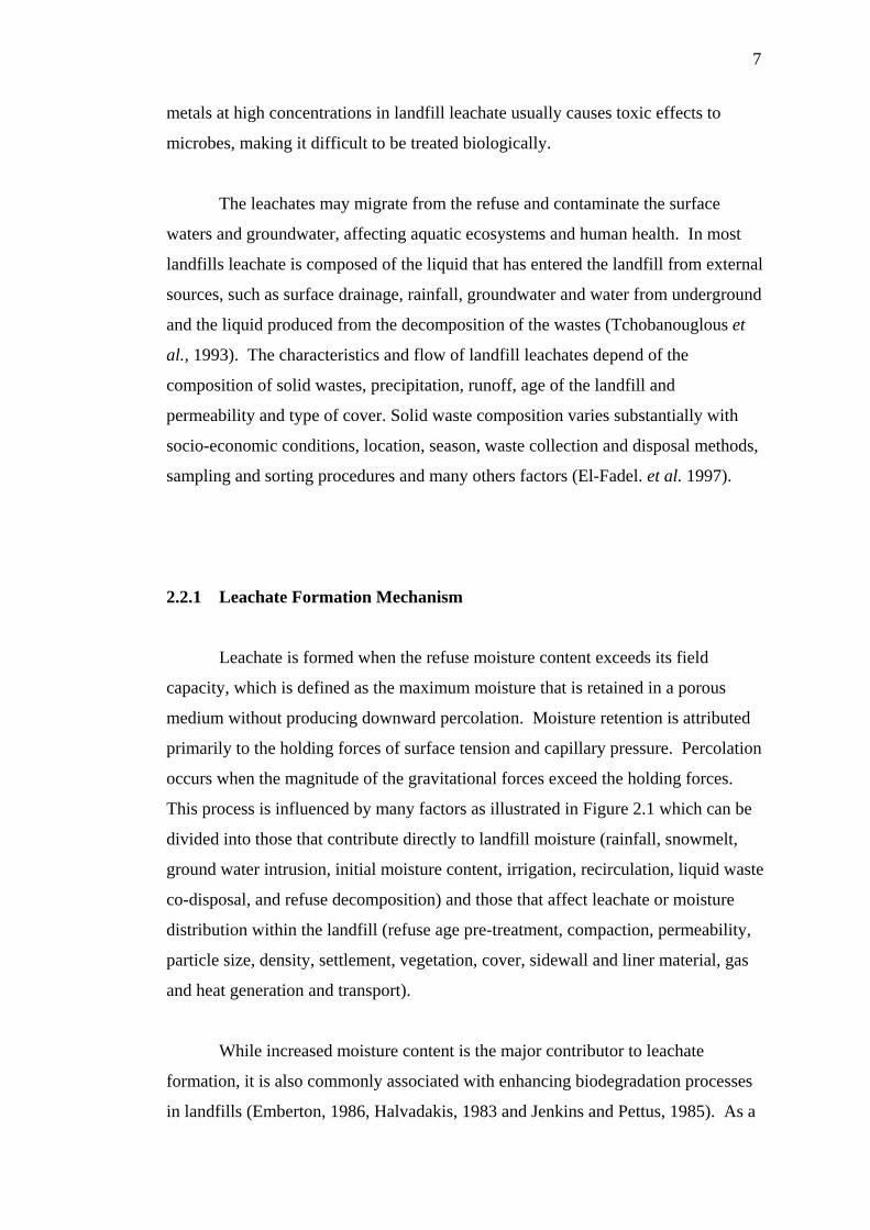
This process is influenced by many factors as illustrated in Figure 2.1 which can be
divided into those that contribute directly to landfill moisture (rainfall, snowmelt,
ground water intrusion, initial moisture content, irrigation, recirculation, liquid waste
co-disposal, and refuse decomposition) and those that affect leachate or moisture
distribution within the landfill (refuse age pre-treatment, compaction, permeability,
particle size, density, settlement, vegetation, cover, sidewall and liner material, gas
and heat generation and transport).
While increased moisture content is the major contributor to leachate
formation, it is also commonly associated with enhancing biodegradation processes
in landfills (Emberton, 1986, Halvadakis, 1983 and Jenkins and Pettus, 1985). As a
8
result, it has been suggested that there are benefits in designing a landfill cover to
capture water (i.e. increase infiltration) to enhance biodegradation thus promoting
rapid stabilization and reducing the time required for the return of the landfill to
beneficial land use (Reinhart, 1995).
Figure 2.1: Factors influencing leachate formation in landfills (El-Fadil, 2002)
In a municipal waste, methane, carbon dioxide, ammonia and hydrogen
sulfide gases are generated due to anaerobic decomposition of the waste. These
gases may dissolve in water and react with the waste or dissolved constituents of the
percolating water. Several other reactions also take place releasing a wide range of
chemicals, depending on the waste type. The percolating water plays a significant
role in leachate generation. It should be noted that even if no water is allowed to
percolate through the waste, a small volume of contaminated liquid is always
expected to form due to biological and chemical reactions. The concentration of
chemical compounds in such liquid is expected to be very high. The percolating
water dilutes the contaminants in addition to aiding its formation. The quantity of
leachate increases due to percolation of water, but at the same time the percolating
dilutes the concentration of contaminants. Both quality and quantity of leachate are
important issues for landfill design.
The four major stages of landfill decomposition are shown in Figure 2.2.
Each stage results in leachate of varying compositions. In the early stages of a
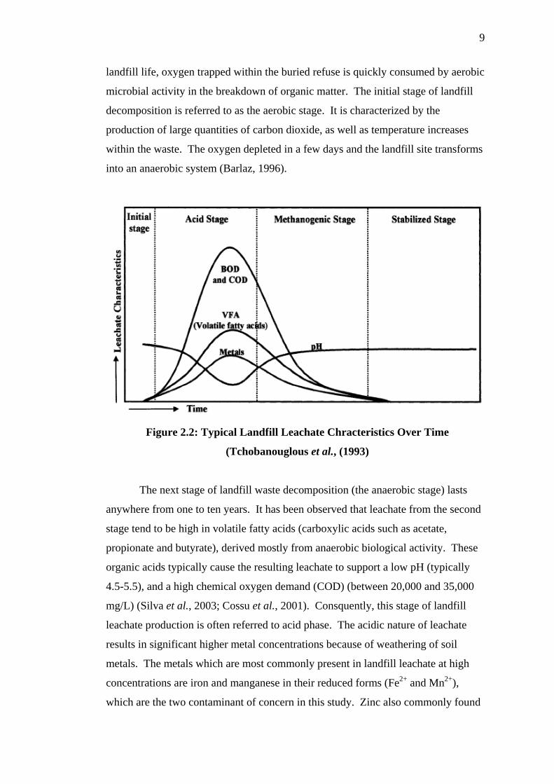
9
landfill life, oxygen trapped within the buried refuse is quickly consumed by aerobic
microbial activity in the breakdown of organic matter. The initial stage of landfill
decomposition is referred to as the aerobic stage. It is characterized by the
production of large quantities of carbon dioxide, as well as temperature increases
within the waste. The oxygen depleted in a few days and the landfill site transforms
into an anaerobic system (Barlaz, 1996).
Figure 2.2: Typical Landfill Leachate Chracteristics Over Time
(Tchobanouglous et al., (1993)
The next stage of landfill waste decomposition (the anaerobic stage) lasts
anywhere from one to ten years. It has been observed that leachate from the second
stage tend to be high in volatile fatty acids (carboxylic acids such as acetate,
propionate and butyrate), derived mostly from anaerobic biological activity. These
organic acids typically cause the resulting leachate to support a low pH (typically
4.5-5.5), and a high chemical oxygen demand (COD) (between 20,000 and 35,000
mg/L) (Silva et al., 2003; Cossu et al., 2001). Consquently, this stage of landfill
leachate production is often referred to acid phase. The acidic nature of leachate
results in significant higher metal concentrations because of weathering of soil
metals. The metals which are most commonly present in landfill leachate at high
concentrations are iron and manganese in their reduced forms (Fe2+ and Mn2+),
which are the two contaminant of concern in this study. Zinc also commonly found
10
in landfill leachate (Liehr et al., 2000). Acid phase leachates also typically contain
elevated levels of biochemical oxygen demand (BOD) and ammonia as a result of
high decomposition activity of landfill leachate organic matter (Barlaz, 1996, Barlaz
and Gabr, 2001).
As landfill continues to mature, the accumulated of carboxylic acids begin to
convert the methane and carbon dioxide by methanogenic bacteria. As their activity
increases, significant methane and carbon dioxide production occurs, marking the
onset of what is termed as methanogenic stage of landfill decomposition. As the
acids are consumed, COD and BOD levels decrease and pH begins to rise. This
phase of decomposition can be expected last anywhere from 30-200 years (Barlaz,
1996).
As time continues to pass and a system matures, waste degradation will
progress closer to completion as all readily biodegradable waste becomes converted
to methane and carbon dioxide. The carboxylic acid concentration decreases and the
pH continue to increase until ultimately the system becomes stabilized. Hence this
final stage of landfill decomposition as referred to as the stabilized or maturation
stages. In this final stage of degradation that leachate would cease to be hazardous to
environment. The stabilized stage is somewhat theoretical, as the time it would take
for complete waste degradation to occur and the landfill to convert back to aerobic
system could very well be on geologic scale and has not fully been observed (Barlaz,
1996, Tchobanouglous et al., 1993).
2.2.2 Composition of leachate
The composition of leachate will influence by types and age of waste
deposited, the prevailing physico-chemical conditions and the microbiology and the
water balance in the landfill (McBean et al., 1995). The leachate quality is quite
variable from site to site depending upon the contents of the stack and its hydrology
(Kadlec, 1999). When water percolates through solid wastes that undergoing
decomposition, both biological materials and chemical constituents are leached into
11
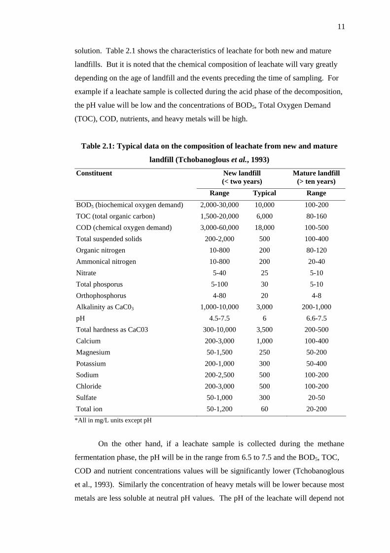
solution. Table 2.1 shows the characteristics of leachate for both new and mature
landfills. But it is noted that the chemical composition of leachate will vary greatly
depending on the age of landfill and the events preceding the time of sampling. For
example if a leachate sample is collected during the acid phase of the decomposition,
the pH value will be low and the concentrations of BOD5, Total Oxygen Demand
(TOC), COD, nutrients, and heavy metals will be high.
Table 2.1: Typical data on the composition of leachate from new and mature
landfill (Tchobanoglous et al., 1993)
Constituent New landfill (< two years)
Mature landfill (> ten years)
Range Typical Range BOD5 (biochemical oxygen demand) 2,000-30,000 10,000 100-200 TOC (total organic carbon) 1,500-20,000 6,000 80-160 COD (chemical oxygen demand) 3,000-60,000 18,000 100-500 Total suspended solids 200-2,000 500 100-400 Organic nitrogen 10-800 200 80-120 Ammonical nitrogen 10-800 200 20-40 Nitrate 5-40 25 5-10 Total phosporus 5-100 30 5-10 Orthophosphorus 4-80 20 4-8 Alkalinity as CaC03 1,000-10,000 3,000 200-1,000 pH 4.5-7.5 6 6.6-7.5 Total hardness as CaC03 300-10,000 3,500 200-500 Calcium 200-3,000 1,000 100-400 Magnesium 50-1,500 250 50-200 Potassium 200-1,000 300 50-400 Sodium 200-2,500 500 100-200 Chloride 200-3,000 500 100-200 Sulfate 50-1,000 300 20-50 Total ion 50-1,200 60 20-200 *All in mg/L units except pH
On the other hand, if a leachate sample is collected during the methane
fermentation phase, the pH will be in the range from 6.5 to 7.5 and the BOD5, TOC,
COD and nutrient concentrations values will be significantly lower (Tchobanoglous
et al., 1993). Similarly the concentration of heavy metals will be lower because most
metals are less soluble at neutral pH values. The pH of the leachate will depend not
12
only on the concentration of the acids that are present but also on the partial pressure
of the CO2 in the landfill gas that is in contact with the leachate.
The biodegradability of the leachate will vary with time. Checking the BOD5
and COD ratio can monitor changes in biodegradability of the leachate. Initially, the
ratios will be in the range of 0.5 or greater. Ratios in the range of 0.4 to 0.6 are
taken, as an indication that the organic matter in the leachate is readily
biodegradable. In mature landfills, the BOD5, COD ratio is often in the range 0.05 to
0.2. The ratio drops because leachate from mature landfills typically contains humic
and fulvic acids, which are not readily biodegradable (Tchobanoglous et al, 1993).
The indicator of the degree of waste decomposition in landfills include: iron,
manganese, COD, BOD, and ammonium concentration, redox potential, alkalinity,
ionic strength, BOD: COD, and sulfite to chlorine ratio (Barlaz, 1996).
2.2.3 Leachate Treatment Method
As a result of the variability in leachate characteristics, the design of leachate
treatment systems is complicated. For example, a treatment plant designed to treat a
leachate with the characteristics reported for a new landfill would be quite different
from one designed to treat the leachate from a mature landfill. The problem of
interpreting the analytical results is complicated further by the fact that the leachate
that is being generated at any point in time is a mixture of leachate derived from
solid waste of different ages. The presence of trace compounds in leachate will
depend on the concentration of these compounds in the gas phase within the landfill.
There are various options to treat landfill leachates. The identification of the
preferred option in specific circumstances is a function of the costs, both operating
and capital, and the limitation impose on the quality and quantity of discharge. The
potentials methods for the management of landfill leachate are mainly recirculation
of leachate through the landfill, disposal off site to sewer for treatment as an
admixture with domestic sewage, physical-chemical treatment, membrane filtration

13
and reverse osmosis, anaerobic biological treatment, aerobic biological treatment,
and constructed wetlands (Kappelmeyer, 2005).
Recirculation of leachates through the landfill allows accelerating
stabilisation processes of solids wastes and, therefore, enhancement of gas
production (Reinhart and Al-Yousfi, 1996). However some problems are also
presented such as perched water tables in the waste, high hydraulic gradient above
the liner, seepage and geotechnical instabilities (Cossu, et al, 2001). Leachate
recirculation also has important consequences with regard to metal contamination of
leachate. The primary removal mechanism for metal in conventionally operated
landfills appears to be washout, although limited chemical precipitation may occur.
In leachate recirculating landfills, the primary metal removal mechanism appears to
be sulfide and hydroxide precipitation. With time, moderate to high molecular
weight humic-like substances are formed from waste organic matter in a process
similar to soil humification. These substances tend to form strong complexes with
heavy metals.
Physical-Chemical precipitation is based on the addition of some chemicals
to remove suspended solids, nitrogen, phosphorus and metals. The main
disadvantages of this technology are associated with its operating costs, high
variability of landfill leachate and sludge produced. Physical-chemical treatments
have been found to be suitable not only for the removal of refractory substances from
stabilized leachate, but also as a refining step for biologically treated leachate. Prior
to discharge, an additional effluent refining using physical-chemical treatments, such
as chemical precipitation, activated carbon adsorption and ion exchange, can be
carried out on-site (Kurniawan et al., 2006).
Other treatment options include the use of more natural engineered systems.
Field and laboratory studies have been conducting using wetland systems to treat
leachate, but with variable results (McBean and Rovers (1999), Liehr et al. (2000)
and Cossu et al. (2001). Inconsistent results can be attributed to the variable nature
of the leachate and the lack of universally accepted design standards for wetland
treatment systems. Besides it is clear that the constructed wetland installed to remove
high organic carbon loads.
14
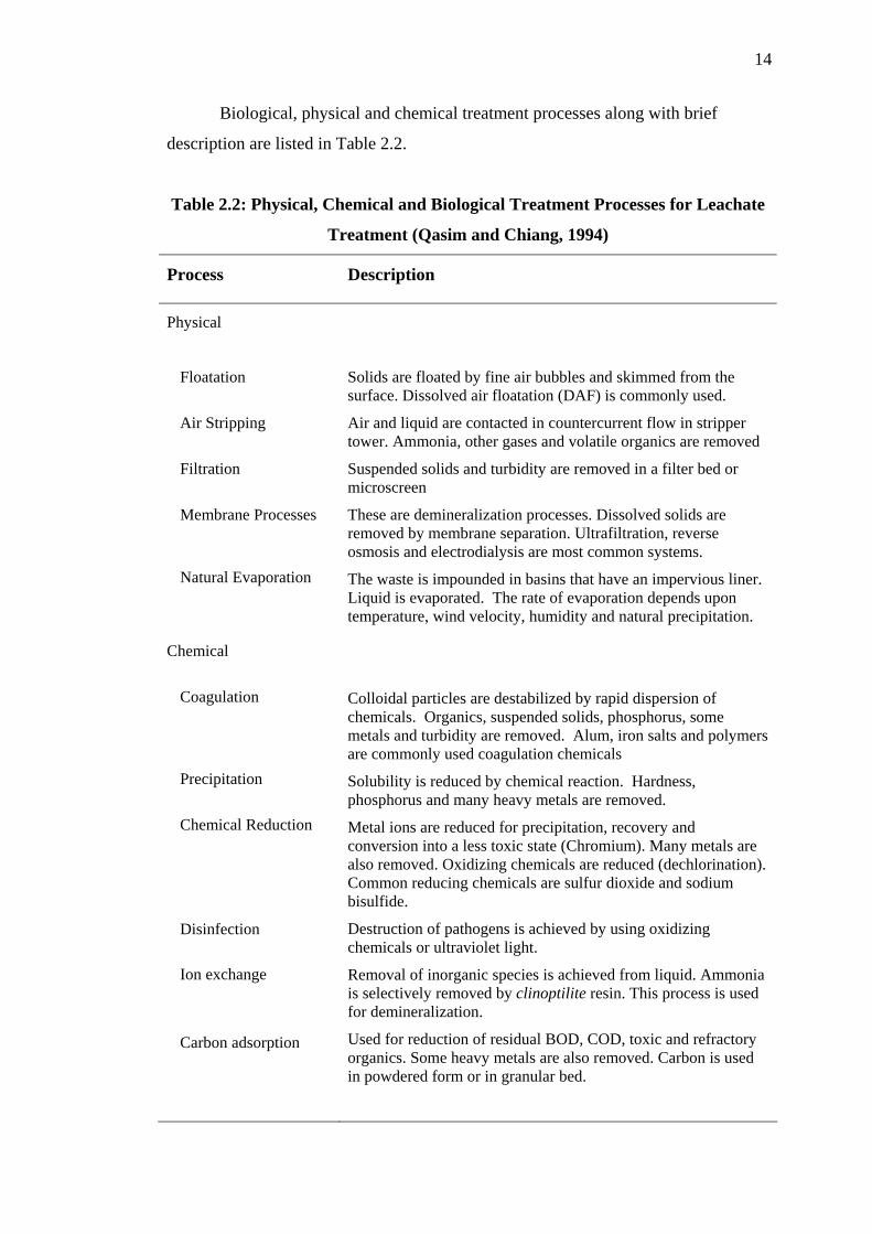
Biological, physical and chemical treatment processes along with brief
description are listed in Table 2.2.
Table 2.2: Physical, Chemical and Biological Treatment Processes for Leachate
Treatment (Qasim and Chiang, 1994)
Process Description
Physical
Floatation
Air Stripping
Filtration
Membrane Processes
Natural Evaporation
Chemical
Coagulation
Precipitation
Chemical Reduction
Disinfection
Ion exchange
Carbon adsorption
Solids are floated by fine air bubbles and skimmed from the surface. Dissolved air floatation (DAF) is commonly used.
Air and liquid are contacted in countercurrent flow in stripper tower. Ammonia, other gases and volatile organics are removed
Suspended solids and turbidity are removed in a filter bed or microscreen
These are demineralization processes. Dissolved solids are removed by membrane separation. Ultrafiltration, reverse osmosis and electrodialysis are most common systems.
The waste is impounded in basins that have an impervious liner. Liquid is evaporated. The rate of evaporation depends upon temperature, wind velocity, humidity and natural precipitation.
Colloidal particles are destabilized by rapid dispersion of chemicals. Organics, suspended solids, phosphorus, some metals and turbidity are removed. Alum, iron salts and polymers are commonly used coagulation chemicals
Solubility is reduced by chemical reaction. Hardness, phosphorus and many heavy metals are removed.
Metal ions are reduced for precipitation, recovery and conversion into a less toxic state (Chromium). Many metals are also removed. Oxidizing chemicals are reduced (dechlorination). Common reducing chemicals are sulfur dioxide and sodium bisulfide.
Destruction of pathogens is achieved by using oxidizing chemicals or ultraviolet light.
Removal of inorganic species is achieved from liquid. Ammonia is selectively removed by clinoptilite resin. This process is used for demineralization.
Used for reduction of residual BOD, COD, toxic and refractory organics. Some heavy metals are also removed. Carbon is used in powdered form or in granular bed.

15
Table 2.2: (continued)
Process Description
Biological
Aerobic
Activated Sludge
Aerated Lagoon
Sequencing Batch Reactor (SBR) Trickling Filters
Rotating Biological Contactor (RBC)
Anaerobic
Conventional
Upflow Anaerobic Sludge Blanket (UASB)
Expended bed or fluidized bed
Aerobic-anaerobic stabilization ponds
Land treatment
Microorganisms are cultivated in the presence of molecular oxygen. Solid are recirculated. The end product is carbon dioxide
In the activated sludge process the food and sludge microorganisms are aerated. The microorganisms are settled and recirculated. Common process modification are conventional, tapered aeration, step aeration, completely mixed, pure oxygen, extended aeration and contact stabilization
Large aeration basins with several days of detention period are used
A SBR is a fill and draw activated sludge treatment system. Food and microorganism contact, organic stabilization, sedimentation and discharge of clarified effluent occur in single basin.
The population of active microorganisms is supported over solid media. The solid media may be of rocks or synthetic material. Water is applied over a bed of rocks or synthetic media. Trickling filters are slow rate, high rate, super rate and two stage.
Consists of a series of closely spaced circular contactor disks of synthetic material. The disks are partly submerged in the wastewater.
The microorganisms are cultivated in the absence of oxygen. The complex organics are solubilized and stabilized. Carbon dioxide, methane and other organic compounds are the end products
High organic strength waste or sludge is stabilized in a standard rate or high rate digester.
Waste enters the bottom and flows upward through a blanket of biologically formed granules or solids. The reactor is filled with the solid media and the waste flows upward. Medium strength wastes are treated in a relatively short hydraulic retention time.
The reactor is filled with media such as sand, coal and gravel. The influent and recycled effluent are pumped from the bottom. The bed is kept in an expanded condition. This process has been used to dilute wastes.
Stabilization ponds are earthen basins with impervious liner. The basins may be aerobic, facultative or anaerobic depending upon the depth and strength of wastes. Source of oxygen is natural aeration.
The waste is applied over land to utilize plants, soil matrix and natural phenomena to treat waste by a combination of physical, chemical and biological means. The methods of land application are slow-rate irrigation, rapid infiltration-percolation and over-land flow.
16
2.3 Constructed Wetlands
Constructed wetland is a mimic of natural wetland and ecological system that
combines physical, chemical and biological treatment mechanisms in removing
pollutants from wastewater as it flow through the wetland. Constructed wetlands
represent an emerging ecotechnological treatment system, which are designed to
overcome the disadvantages of natural wetlands (Lim, 2002). It is man-made systems
that involve altering the existing terrain to simulate wetlands conditions. It has
grown in popularity for wastewater treatment since the early 1980s (Reed et al.,
1995). Its increasing popularity can be attributed to several factors which are it less
costly to build and operate than other conventional treatment facilities, low energy
consumption and maintenance requirements and benefits of increased wildlife habitat
(IWA, 2000)
The use of wetlands to treat effluent is not a new idea. Constructed wetlands,
have been used to treat acid mine drainage, stormwater runoff, municipal
wastewater, industrial wastewater and agricultural effluent form livestock operations.
Researchers have demonstrate that treatment wetland system can remove significant
amounts of suspended solids, organic matter, nitrogen, phosphorus, trace elements,
heavy metals and microorganisms contained in wastewater (Kadlec and Knight,
1996). They primarily attempt to replicate treatment that has been observed to occur
when polluted water enters natural wetlands. These wetlands have been seen to
purify water by removing organic compounds and oxidizing ammonia, reducing
nitrates and removing phosphorus and some metals.
2.3.1 Types of Constructed Wetland
The constructed wetlands systems can have different flow formats, media and
types of emergent vegetation planted. The basic classification is based on the type of
macrophytic growth (emergent, submerged, free floating and rooted with floating
leaves), further classification is usually based on the water flow regime (free water
surface flow, sub-surface vertical or horizontal flow). Recently, the combinations of
17
various types of constructed have been used to enhance the treatment effect,
especially for nitrogen (Vymazal, 2005).
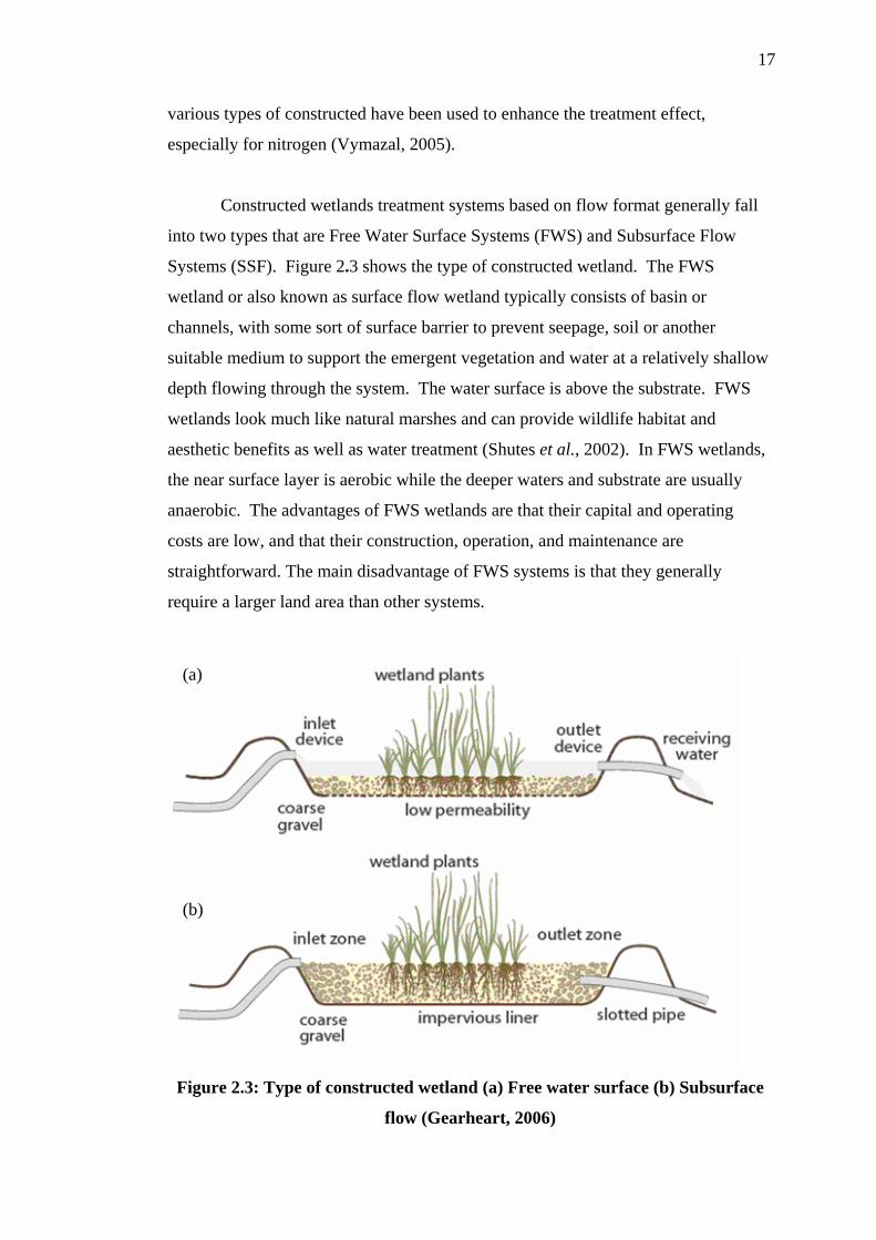
Constructed wetlands treatment systems based on flow format generally fall
into two types that are Free Water Surface Systems (FWS) and Subsurface Flow
Systems (SSF). Figure 2.3 shows the type of constructed wetland. The FWS
wetland or also known as surface flow wetland typically consists of basin or
channels, with some sort of surface barrier to prevent seepage, soil or another
suitable medium to support the emergent vegetation and water at a relatively shallow
depth flowing through the system. The water surface is above the substrate. FWS
wetlands look much like natural marshes and can provide wildlife habitat and
aesthetic benefits as well as water treatment (Shutes et al., 2002). In FWS wetlands,
the near surface layer is aerobic while the deeper waters and substrate are usually
anaerobic. The advantages of FWS wetlands are that their capital and operating
costs are low, and that their construction, operation, and maintenance are
straightforward. The main disadvantage of FWS systems is that they generally
require a larger land area than other systems.
(a)
(b)
Figure 2.3: Type of constructed wetland (a) Free water surface (b) Subsurface
flow (Gearheart, 2006)
18
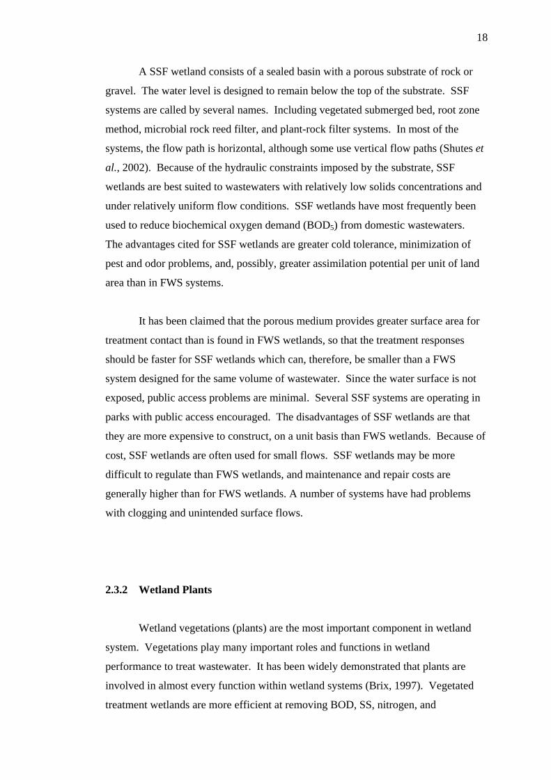
A SSF wetland consists of a sealed basin with a porous substrate of rock or
gravel. The water level is designed to remain below the top of the substrate. SSF
systems are called by several names. Including vegetated submerged bed, root zone
method, microbial rock reed filter, and plant-rock filter systems. In most of the
systems, the flow path is horizontal, although some use vertical flow paths (Shutes et
al., 2002). Because of the hydraulic constraints imposed by the substrate, SSF
wetlands are best suited to wastewaters with relatively low solids concentrations and
under relatively uniform flow conditions. SSF wetlands have most frequently been
used to reduce biochemical oxygen demand (BOD5) from domestic wastewaters.
The advantages cited for SSF wetlands are greater cold tolerance, minimization of
pest and odor problems, and, possibly, greater assimilation potential per unit of land
area than in FWS systems.
It has been claimed that the porous medium provides greater surface area for
treatment contact than is found in FWS wetlands, so that the treatment responses
should be faster for SSF wetlands which can, therefore, be smaller than a FWS
system designed for the same volume of wastewater. Since the water surface is not
exposed, public access problems are minimal. Several SSF systems are operating in
parks with public access encouraged. The disadvantages of SSF wetlands are that
they are more expensive to construct, on a unit basis than FWS wetlands. Because of
cost, SSF wetlands are often used for small flows. SSF wetlands may be more
difficult to regulate than FWS wetlands, and maintenance and repair costs are
generally higher than for FWS wetlands. A number of systems have had problems
with clogging and unintended surface flows.
2.3.2 Wetland Plants
Wetland vegetations (plants) are the most important component in wetland
system. Vegetations play many important roles and functions in wetland
performance to treat wastewater. It has been widely demonstrated that plants are
involved in almost every function within wetland systems (Brix, 1997). Vegetated
treatment wetlands are more efficient at removing BOD, SS, nitrogen, and
19
phosphorus than unvegetated wetlands (Yang et al., 2001, Huett et al., 2005).
Specifically, aquatic plants in treatment wetlands act as physical filters (Hammer,
1989, Brix, 1994), take up nutrients and other constituents (Greenway and Woolley,
1999, Liu et al., 2000), provide a substrate for microbiota and microinvertebtares
(Kadlec and Knight, 1996, and Wetzel, 2000), contribute carbon and create anaerobic
zones for denitrification (Stefan et al., 1994, Reed et al., 1995, Ingersoll and Baker,
1998), add oxygen to sediment zones where nitrification occur (Cronk and Fennessy,
2001) and enhance denitrification by pulling nitrates from the water column into
anaerobic zones within the sediments as the roots actively absorb water needed for
transpiration (Martin et al., 2003).
Numerous studies have conformed that water treatment is improved in
vegetated systems compared to system containing no plants. However, most of these
studies were done when the vegetation was new and actively growing, absorbing
abundant amounts of nutrients, minerals and waters as the plant transpired and
produced large amount of biomass (Thullen et al., 2005). The vegetation growing in
constructed wetlands have several properties in relation to the treatment processes
that make them an essential component of the design. The major roles of wetland
plants in constructed wetlands are summarized in Table 2.3.
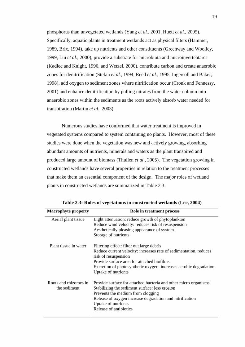
Table 2.3: Roles of vegetations in constructed wetlands (Lee, 2004)
Macrophyte property Role in treatment process
Aerial plant tissue Light attenuation: reduce growth of phytoplankton Reduce wind velocity: reduces risk of resuspension Aesthetically pleasing appearance of system Storage of nutrients
Plant tissue in water Filtering effect: filter out large debris Reduce current velocity: increases rate of sedimentation, reduces risk of resuspension Provide surface area for attached biofilms Excretion of photosynthetic oxygen: increases aerobic degradation Uptake of nutrients
Roots and rhizomes in the sediment
Provide surface for attached bacteria and other micro organisms Stabilizing the sediment surface: less erosion Prevents the medium from clogging Release of oxygen increase degradation and nitrification Uptake of nutrients Release of antibiotics
20
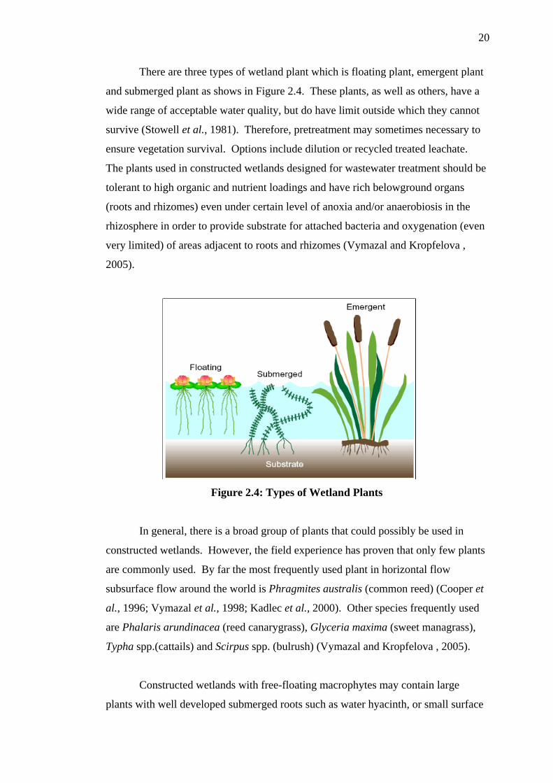
There are three types of wetland plant which is floating plant, emergent plant
and submerged plant as shows in Figure 2.4. These plants, as well as others, have a
wide range of acceptable water quality, but do have limit outside which they cannot
survive (Stowell et al., 1981). Therefore, pretreatment may sometimes necessary to
ensure vegetation survival. Options include dilution or recycled treated leachate.
The plants used in constructed wetlands designed for wastewater treatment should be
tolerant to high organic and nutrient loadings and have rich belowground organs
(roots and rhizomes) even under certain level of anoxia and/or anaerobiosis in the
rhizosphere in order to provide substrate for attached bacteria and oxygenation (even
very limited) of areas adjacent to roots and rhizomes (Vymazal and Kropfelova ,
2005).
Figure 2.4: Types of Wetland Plants
In general, there is a broad group of plants that could possibly be used in
constructed wetlands. However, the field experience has proven that only few plants
are commonly used. By far the most frequently used plant in horizontal flow
subsurface flow around the world is Phragmites australis (common reed) (Cooper et
al., 1996; Vymazal et al., 1998; Kadlec et al., 2000). Other species frequently used
are Phalaris arundinacea (reed canarygrass), Glyceria maxima (sweet managrass),
Typha spp.(cattails) and Scirpus spp. (bulrush) (Vymazal and Kropfelova , 2005).
Constructed wetlands with free-floating macrophytes may contain large
plants with well developed submerged roots such as water hyacinth, or small surface

21
floating plants with little or no roots such as duckweed (Greenway, 1997). Due to
constructed wetland large potential for nutrient removal from wastewater, the water
hyacinth is the one that stimulated extensive experimentation. The capability of
water hyacinth to purify wastewater is well documented (Reddy and Sutton, 1984;
Reddy and DeBusk, 1985; DeBusk et al., 1989, Reddy and D’Angelo, 1990). The
extensive root system of the weed provides a large surface area for attached
microorganisms thus increasing the potential for decomposition of organic matter.
Plant uptake is the major process for nutrient removal from wastewater systems
containing water hyacinth plants (Reddy and Sutton, 1984). Nitrogen is removed
through plant uptake (with harvesting), ammonia is removed through volatilisation
and nitrification/denitrification, and phosphorus is removed through plant uptake.
Water hyacinth wastewater treatment systems produce large amounts of excess
biomass given the rapid growth rate of the plant.
Several processes are envisioned as being effective in pollutant reduction:
phytoextraction, phytostabilization, transpiration, and rhizofiltration. In particular,
vegetation fosters and provide several storage and reduction mechanisms.
Phytoextraction refers to plant uptake of toxicants, which is known to occur and has
been studied in the stormwater and mine water treatment wetland context. However,
in many cases the contaminant is selectively bound up in belowground tissues, roots
and rhizomes, and is not readily harvested. Metals are taken up by plants, and in
many cases stored preferentially in the roots and rhizomes. In order for the metals to
be removed from the system, the plant need to be harvested frequently and processed
to reclaim the metals (Cronk and Fennessy, 2001).
Phytostabilization refers to the use of plants as a physical means of holding
soils and treated matrices in place. This process is also one of the principal
underpinnings of treatment wetlands, as it relates to sediment trapping and erosion
prevention in those systems. Wetland plants possess the ability to transfer significant
quantities of gases to and from their root zone and the atmosphere (Brix, 1997). This
ability is part of their adaptation required for survival in flooded environments.
Stems and leaves of wetland plants contain airways that transport oxygen to the roots
and vent water vapor, methane, and carbon dioxide to the atmosphere (Sorrel and
Boon, 1994).
22
There may also be transport of other gaseous constituents, such as nitrogen
and nitrogen oxides, and volatile hydrocarbons. The dominant gas outflow is water
vapor, creating a transpiration flux upward through the plant. Rhizofiltration refers
to a set of processes that occur in the root zone, resulting in the transformation and
immobilization of some contaminants. Plants help create the vertical redox gradients
that foster degrading organisms.
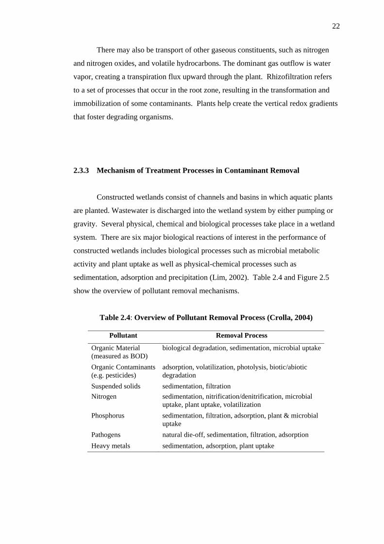
2.3.3 Mechanism of Treatment Processes in Contaminant Removal
Constructed wetlands consist of channels and basins in which aquatic plants
are planted. Wastewater is discharged into the wetland system by either pumping or
gravity. Several physical, chemical and biological processes take place in a wetland
system. There are six major biological reactions of interest in the performance of
constructed wetlands includes biological processes such as microbial metabolic
activity and plant uptake as well as physical-chemical processes such as
sedimentation, adsorption and precipitation (Lim, 2002). Table 2.4 and Figure 2.5
show the overview of pollutant removal mechanisms.
Table 2.4: Overview of Pollutant Removal Process (Crolla, 2004)
Pollutant Removal Process
Organic Material (measured as BOD)
biological degradation, sedimentation, microbial uptake
Organic Contaminants (e.g. pesticides)
adsorption, volatilization, photolysis, biotic/abiotic degradation
Suspended solids sedimentation, filtration Nitrogen sedimentation, nitrification/denitrification, microbial
uptake, plant uptake, volatilization Phosphorus sedimentation, filtration, adsorption, plant & microbial
uptake Pathogens natural die-off, sedimentation, filtration, adsorption Heavy metals sedimentation, adsorption, plant uptake
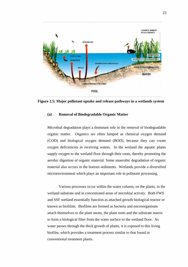
23
Figure 2.5: Major pollutant uptake and release pathways in a wetlands system
(a) Removal of Biodegradable Organic Matter
Microbial degradation plays a dominant role in the removal of biodegradable
organic matter. Organics are often lumped as chemical oxygen demand
(COD) and biological oxygen demand (BOD), because they can create
oxygen deficiencies in receiving waters. In the wetland the aquatic plants
supply oxygen to the wetland floor through their roots, thereby promoting the
aerobic digestion of organic material. Some anaerobic degradation of organic
material also occurs in the bottom sediments. Wetlands provide a diversified
microenvironment which plays an important role in pollutant processing.
Various processes occur within the water column, on the plants, in the
wetland substrate and in concentrated areas of microbial activity. Both FWS
and SSF wetland essentially function as attached growth biological reactor or
known as biofilms. Biofilms are formed as bacteria and microorganisms
attach themselves to the plant stems, the plant roots and the substrate matrix
to form a biological filter from the water surface to the wetland floor. As
water passes through the thick growth of plants, it is exposed to this living
biofilm, which provides a treatment process similar to that found in
conventional treatment plants.

24
(b) Removal of Suspended Solids
The removal of suspended solid (SS) in a wetlands system is usually a
concomitant aspect of system design in the typical wastewater treatment
situation. Most of the solids are removed through sedimentation and
filtration, as vegetation obstructs the flow and reduces velocities. Thus SS
removal in and of itself is not a design variable in the normal sense, though
solids deposition and accumulation in wetlands systems must be considered
during system design. In most applications, a sedimentation pond is added
upstream of the wetland cells to promote the removal of larger sediment
particles and minimize the chance of clogging the wetland cells. These
processes remove a significant portion of the BOD, nutrients (mostly nitrogen
and phosphorus) and pathogens.
(c) Removal of Nutrients
Reduction of nutrients (nitrogen and phosphorus compounds), requires the
longest detention of any the pollutants. The principal nitrogen removal
mechanism operative in wetlands systems is bacterial nitrification/
denitrification (not plant uptake); therefore, nitrogen removal in wetlands
systems is a function of climatic conditions. The bacteria present in the water
(Nitrosomonas) oxidize ammonia to nitrite in an aerobic reaction. The nitrite
is then oxidized aerobically by another bacteria (Nitrobacter) forming nitrate.
Denitrification occurs as nitrate is reduced to gaseous forms under anaerobic
conditions in the litter layer of the wetland substrate. This reaction is
catalyzed by the denitrifying bacteria Pseudomonas spp. and other bacteria.
Phosphorus is stored in new wetland sediments. Nitrogen is also
stored, but in larger measure is sequentially transformed, ultimately leaving
the wetland as ammonia through volatilization. The mechanism of
phosphorus is through adsorption and uptake by plants. Phosphorus removal
in wetlands is based mainly on the phosphorus cycle and can involve a
number of processes such as adsorption, filtration, sedimentation,
complexation/precipitation and assimilation/uptake. Because phosphorus

25
removal in wetlands is less effective than nitrogen removal, a post wetland
polishing step may be required in the form of vegetated filter strips, irrigation
or phosphorus adsorption media.
(d) Metal Removal
Heavy metals are common environmental pollutants that are produced as the
result of industrial, commercial and domestic activities. It is important to
removed the metal from wastewater flows they enter natural waters (Knight,
1997). Kadlec and Knight (1996) report the removal of several metals in
treatment wetlands including aluminium, arsenic, cadmium, copper, iron,
lead, manganese, mercury, nickel, silver and zinc. Metals are removed in
treatment wetlands by three major mechanisms (Kadlec and Knight, 1996):
i. Binding to soil, sediments, particulates and soluble organic by cation
exhange and chelation;
ii. Precipitation as insoluble salts, principally sulfides and
oxyhydroxides; and
iii. Uptake by plants, including algae and by bacteria
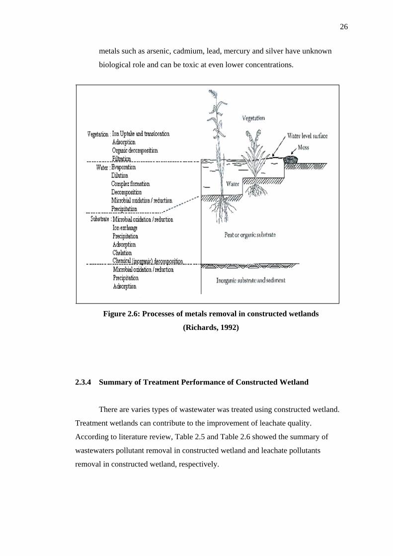
The processes of metal removal in wetlands also have been reviewed
by Richards (1992) and are shown in Figure 2.6. The predominant removal
mechanisms in the artificial wetlands were attributed to precipitation-
absorption phenomena. Precipitation was enhanced by wetlands metabolism,
which increased the pH of inflowing acidic waters to near neutrality. Trace
metals have a high affinity for adsorption and complication with organic
material and are accumulated in wetlands ecosystem.
Plant uptake and microbial transformations may also be of
importance. Although some metals are required for plant and animal growth
in trace quantities (such as barium, beryllium, boron, chromium, cobalt,
copper, iron, magnesium, manganese, nickel, selenium, sulphur, molybdenum
and zinc), these same metals can be toxic at higher concentrations. Other
26
metals such as arsenic, cadmium, lead, mercury and silver have unknown
biological role and can be toxic at even lower concentrations.
Figure 2.6: Processes of metals removal in constructed wetlands
(Richards, 1992)
2.3.4 Summary of Treatment Performance of Constructed Wetland
There are varies types of wastewater was treated using constructed wetland.
Treatment wetlands can contribute to the improvement of leachate quality.
According to literature review, Table 2.5 and Table 2.6 showed the summary of
wastewaters pollutant removal in constructed wetland and leachate pollutants
removal in constructed wetland, respectively.
27
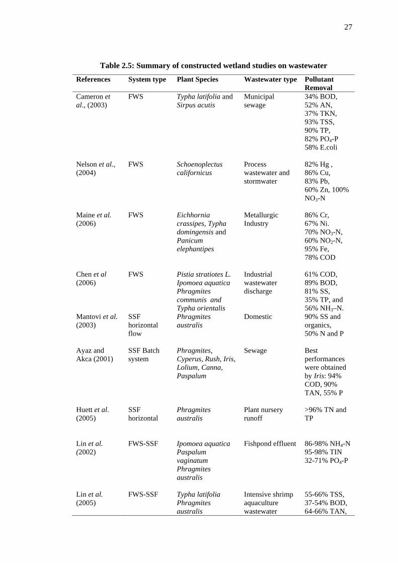
Table 2.5: Summary of constructed wetland studies on wastewater
References System type Plant Species Wastewater type Pollutant Removal
Cameron et al., (2003)
FWS Typha latifolia and Sirpus acutis
Municipal sewage
34% BOD, 52% AN, 37% TKN, 93% TSS, 90% TP, 82% PO4-P 58% E.coli
Nelson et al., (2004)
FWS Schoenoplectus californicus
Process wastewater and stormwater
82% Hg , 86% Cu, 83% Pb, 60% Zn, 100% NO3-N
Maine et al. (2006)
FWS Eichhornia crassipes, Typha domingensis and Panicum elephantipes
Metallurgic Industry
86% Cr, 67% Ni. 70% NO3-N, 60% NO2-N, 95% Fe, 78% COD
Chen et al (2006)
FWS Pistia stratiotes L. Ipomoea aquatica Phragmites communis and Typha orientalis
Industrial wastewater discharge
61% COD, 89% BOD, 81% SS, 35% TP, and 56% NH3–N.
Mantovi et al. (2003)
SSF horizontal flow
Phragmites australis
Domestic 90% SS and organics, 50% N and P
Ayaz and Akca (2001)
SSF Batch system
Phragmites, Cyperus, Rush, Iris, Lolium, Canna, Paspalum
Sewage Best performances were obtained by Iris: 94% COD, 90% TAN, 55% P
Huett et al. (2005)
SSF horizontal
Phragmites australis
Plant nursery runoff
>96% TN and TP
Lin et al. (2002)
FWS-SSF Ipomoea aquatica Paspalum vaginatum Phragmites australis
Fishpond effluent 86-98% NH4-N 95-98% TIN 32-71% PO4-P
Lin et al. (2005)
FWS-SSF Typha latifolia Phragmites australis
Intensive shrimp aquaculture wastewater
55-66% TSS, 37-54% BOD, 64-66% TAN,
28
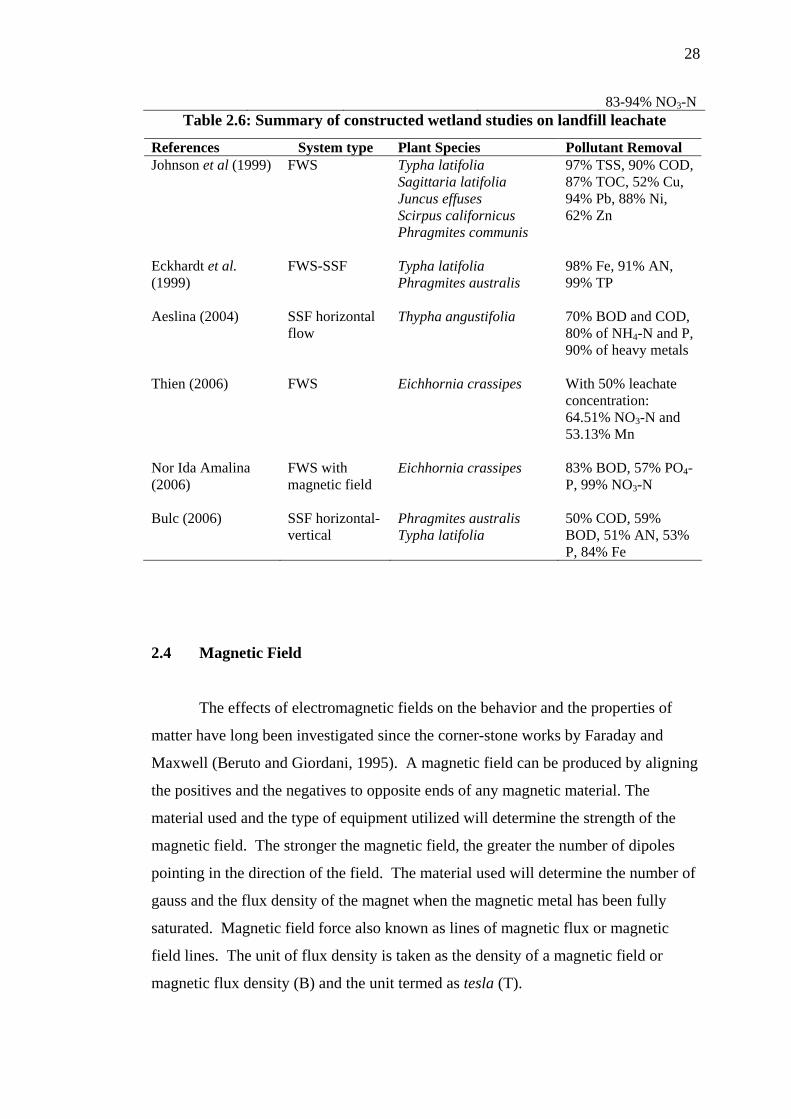
83-94% NO3-N Table 2.6: Summary of constructed wetland studies on landfill leachate
References System type Plant Species Pollutant Removal Johnson et al (1999) FWS Typha latifolia
Sagittaria latifolia Juncus effuses Scirpus californicus Phragmites communis
97% TSS, 90% COD, 87% TOC, 52% Cu, 94% Pb, 88% Ni, 62% Zn
Eckhardt et al. (1999)
FWS-SSF Typha latifolia Phragmites australis
98% Fe, 91% AN, 99% TP
Aeslina (2004) SSF horizontal flow
Thypha angustifolia 70% BOD and COD, 80% of NH4-N and P, 90% of heavy metals
Thien (2006) FWS Eichhornia crassipes With 50% leachate concentration: 64.51% NO3-N and 53.13% Mn
Nor Ida Amalina (2006)
FWS with magnetic field
Eichhornia crassipes 83% BOD, 57% PO4-P, 99% NO3-N
Bulc (2006) SSF horizontal-vertical
Phragmites australis Typha latifolia
50% COD, 59% BOD, 51% AN, 53% P, 84% Fe
2.4 Magnetic Field
The effects of electromagnetic fields on the behavior and the properties of
matter have long been investigated since the corner-stone works by Faraday and
Maxwell (Beruto and Giordani, 1995). A magnetic field can be produced by aligning
the positives and the negatives to opposite ends of any magnetic material. The
material used and the type of equipment utilized will determine the strength of the
magnetic field. The stronger the magnetic field, the greater the number of dipoles
pointing in the direction of the field. The material used will determine the number of
gauss and the flux density of the magnet when the magnetic metal has been fully
saturated. Magnetic field force also known as lines of magnetic flux or magnetic
field lines. The unit of flux density is taken as the density of a magnetic field or
magnetic flux density (B) and the unit termed as tesla (T).
29
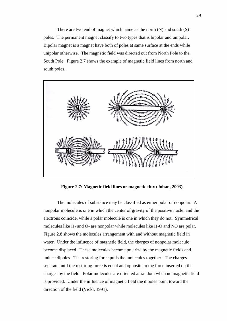
There are two end of magnet which name as the north (N) and south (S)
poles. The permanent magnet classify to two types that is bipolar and unipolar.
Bipolar magnet is a magnet have both of poles at same surface at the ends while
unipolar otherwise. The magnetic field was directed out from North Pole to the
South Pole. Figure 2.7 shows the example of magnetic field lines from north and
south poles.
Figure 2.7: Magnetic field lines or magnetic flux (Johan, 2003)
The molecules of substance may be classified as either polar or nonpolar. A
nonpolar molecule is one in which the center of gravity of the positive nuclei and the
electrons coincide, while a polar molecule is one in which they do not. Symmetrical
molecules like H2 and O2 are nonpolar while molecules like H2O and NO are polar.
Figure 2.8 shows the molecules arrangement with and without magnetic field in
water. Under the influence of magnetic field, the charges of nonpolar molecule
become displaced. These molecules become polarize by the magnetic fields and
induce dipoles. The restoring force pulls the molecules together. The charges
separate until the restoring force is equal and opposite to the force inserted on the
charges by the field. Polar molecules are oriented at random when no magnetic field
is provided. Under the influence of magnetic field the dipoles point toward the
direction of the field (Vickl, 1991).

30
Figure 2.8: Molecules Arrangement with and without magnetic field in water
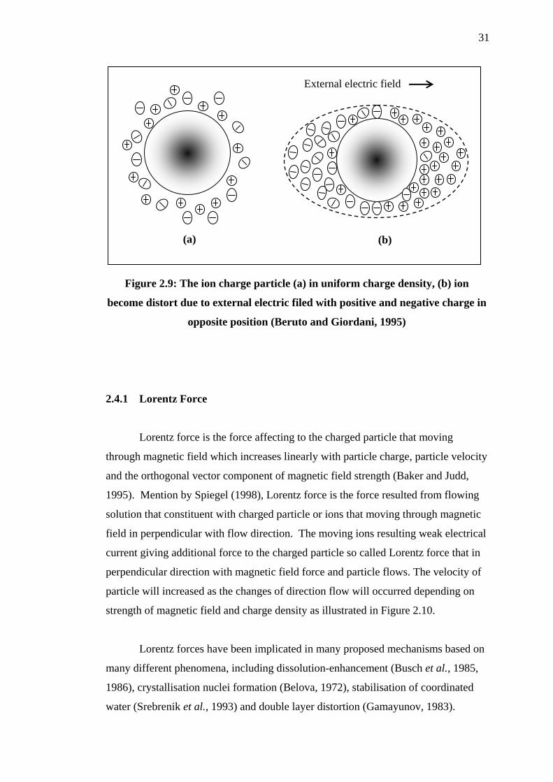
Figure 2.9 shows the forces affecting the particle when magnetic field is
applied in perpendicular direction. This force will separate the particle with positive
and negative charge. Beruto and Giordani (1995) revealed that, the surface of the
solid or liquid interface nucleus can be described as a surface characterized by a
uniform charge density (Figure 2.9a). When an external electric field is applied, the
charge density is modified by a polarization effect (Figure 2.9b).
Numerous studies on effects of exposure to a magnetic field have been
studied especially in scale reduction and formation or crystallization of calcium
carbonate. Magnetic fields have proven can increase the formation of sediment
particles. The magnetic field affected the equilibrium and stabilization of suspended
particle that cause the particles to settle after aggregation process. Magnetic
separations are usually effective only for particles (i.e., collections of molecules)
because the strength of the interaction of magnetic fields with single molecules is
ordinarily much less than thermal energy in solution.
31
(a) (b)
External electric field
Figure 2.9: The ion charge particle (a) in uniform charge density, (b) ion
become distort due to external electric filed with positive and negative charge in
opposite position (Beruto and Giordani, 1995)
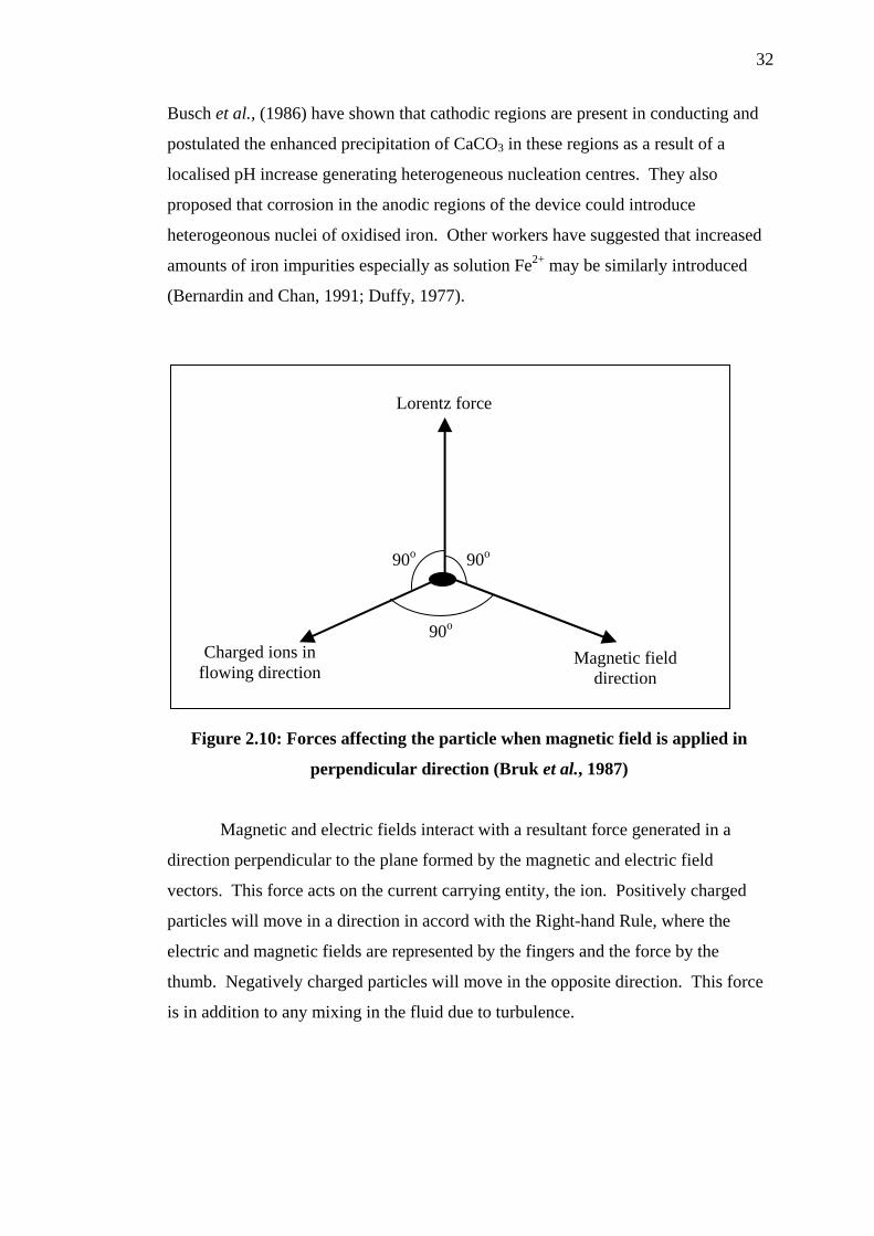
2.4.1 Lorentz Force
Lorentz force is the force affecting to the charged particle that moving
through magnetic field which increases linearly with particle charge, particle velocity
and the orthogonal vector component of magnetic field strength (Baker and Judd,
1995). Mention by Spiegel (1998), Lorentz force is the force resulted from flowing
solution that constituent with charged particle or ions that moving through magnetic
field in perpendicular with flow direction. The moving ions resulting weak electrical
current giving additional force to the charged particle so called Lorentz force that in
perpendicular direction with magnetic field force and particle flows. The velocity of
particle will increased as the changes of direction flow will occurred depending on
strength of magnetic field and charge density as illustrated in Figure 2.10.
Lorentz forces have been implicated in many proposed mechanisms based on
many different phenomena, including dissolution-enhancement (Busch et al., 1985,
1986), crystallisation nuclei formation (Belova, 1972), stabilisation of coordinated
water (Srebrenik et al., 1993) and double layer distortion (Gamayunov, 1983).
32
Busch et al., (1986) have shown that cathodic regions are present in conducting and
postulated the enhanced precipitation of CaCO3 in these regions as a result of a
localised pH increase generating heterogeneous nucleation centres. They also
proposed that corrosion in the anodic regions of the device could introduce
heterogeonous nuclei of oxidised iron. Other workers have suggested that increased
amounts of iron impurities especially as solution Fe2+ may be similarly introduced
(Bernardin and Chan, 1991; Duffy, 1977).
90o90o
Charged ions in flowing direction
Magnetic field direction
Lorentz force
90o
Figure 2.10: Forces affecting the particle when magnetic field is applied in
perpendicular direction (Bruk et al., 1987)
Magnetic and electric fields interact with a resultant force generated in a
direction perpendicular to the plane formed by the magnetic and electric field
vectors. This force acts on the current carrying entity, the ion. Positively charged
particles will move in a direction in accord with the Right-hand Rule, where the
electric and magnetic fields are represented by the fingers and the force by the
thumb. Negatively charged particles will move in the opposite direction. This force
is in addition to any mixing in the fluid due to turbulence.

33
2.4.2 Variation
Devices are available in two installation variations and three operational
variations. First to be discussed are the two installation variations: invasive and non-
invasive. Invasive devices are those which have part or all of the operating
equipment within the flow field. Therefore, these devices require the removal of a
section of the pipe for insertion of the device. This, of course, necessitates an
amount of time for the pipe to be out of service. Non-invasive devices are
completely external to the pipe, and thus can be installed while the pipe is in
operation. Figure 2.11 illustrates the two installation variations for magnet. The
devices illustrated are examples of permanent magnet devices.
Figure 2.11: Illustration of classes of magnetic devices by installation location
(Herzog et al., 1989)
The operational variation includes: magnetic, more correctly permanent
magnet; electromagnetic, where magnetic field is generated via electromagnet, and
electrostatic, where an electric field is imposed on the water flow, which serves to
attract or repel the ions and, in addition, generates a magnetic field. Electrostatic
units are always invasive. The other two types can be either invasive or non-invasive.
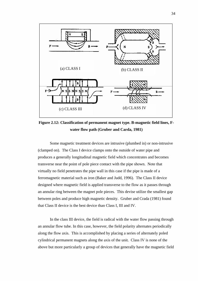
Gruber and Carda (1981) classify magnetic treatment devices utilizing
permanent magnet into four categories where each employing different orientations
of magnetic field. The four types are shown in Figure 2.12. Class II and Class III
devices units employ a field that is orientated approximately orthogonal to the
direction of flow whilst others (Class I and IV) employ a mostly parallel field.
34
(c) CLASS III (d) CLASS IV
(b) CLASS II (a) CLASS I
Figure 2.12: Classification of permanent magnet type. B-magnetic field lines, F-
water flow path (Gruber and Carda, 1981)
Some magnetic treatment devices are intrusive (plumbed in) or non-intrusive
(clamped on). The Class I device clamps onto the outside of water pipe and
produces a generally longitudinal magnetic field which concentrates and becomes
transverse near the point of pole piece contact with the pipe shown. Note that
virtually no field penetrates the pipe wall in this case if the pipe is made of a
ferromagnetic material such as iron (Baker and Judd, 1996). The Class II device
designed where magnetic field is applied transverse to the flow as it passes through
an annular ring between the magnet pole pieces. This devise utilize the smallest gap
between poles and produce high magnetic density. Gruber and Crada (1981) found
that Class II device is the best device than Class I, III and IV.
In the class III device, the field is radical with the water flow passing through
an annular flow tube. In this case, however, the field polarity alternates periodically
along the flow axis. This is accomplished by placing a series of alternately poled
cylindrical permanent magnets along the axis of the unit. Class IV is none of the
above but more particularly a group of devices that generally have the magnetic field
35
parallel to the flow, using a collinear solenoid, and some type of spiral metallic
element that rotates inside the pipe containing the field.
2.4.3 Magnetic Memory
The magnetic effects can remains at the particle for certain periods after
expose to the magnetic field. This behaviour was so called “magnetic memory”.
The effect of memory magnet was mention by Ellingsen and Kristiansen (1979),
Highashitani et al. (1992), Highashitani et al. (1993) and Barrett and Parsons (1997).
Baker and Judd (1996) recorded almost research result. Magnetic memory effect to
particles reported ranges between 10 minutes (Ellingsen and Kristiansen, 1979) until
120 hour (Highashitani et al., 1993) and 143 hour (Highashitani et al. 1992) after the
magnetic exposure is completed. Highashitani et al. 1995 also reported that
magnetic memory maintained to 6 days after the magnetic field is exposed to CaCO3
solution, for at least 60 hours after exposure (Barrett and Parsons, 1997), and 200
hours (Coey and Cass, 2000).
According to Barret and Parsons (1998), light absorption through Na2CO3/
CaCl2 solution that exposed to magnetic field is small and this value sustain until 60
hours. The magnetic memory outcomes differ to Ozeki et al., (1991) and Lipus et
al., (2001) researches where the magnetic effect loss after magnet is draw out.
2.4.4 Magnetic Treatment System
Differences in device types arise from the field strength of the magnet, the
frequency of the field and the flow regime through the field. From literature review,
the researches typically there are 3 general approaches to magnetic field systems.
The approach for magnetic treatment is as follow:

36
(i) Static magnetic field or without flow;
(ii) Single flow magnetic field; and
(iii) Circulation flow magnetic field
Static magnetic field or no flow magnetic field means the sample was
exposed to the permanent magnet for a certain time without any circulation or
flowing. This process has less contribution in aggregation and crystallization.
Highashitani et al. (1993) revealed that, nucleation frequency was decreased, but the
crystallization of CaCO3 was increasing when applying high strength of magnetic
field. While Barret and Parsons (1998) recorded that magnetic fields influence the
formation of CaCO3 by the suppression of nucleation and acceleration in crystal
growth.
The second method, single flow, means the sample was allowed to flow
through the magnetic filed for one time only. The outcome of the research conducted
by the some researchers was expressed in negative result contrast to the many
apparently positive results reported in both scientific and trade literature for
recirculatory or other systems where magnetic exposure is prolonged. Study done by
Duffy (1977) recorded that, there were no differences in precipitation of particle, no
effect occurs on precipitation of CaCO3 (Hasson and Bramson, 1981) and no changes
in physical-chemical properties in distil water when expose to magnetic field (Gonet,
1985).
Circulation of sample through the magnetic field is the third method. In this
study, the circulation flow magnetic treatment is applied. Magnetic treatment for
water and solution is reported most successful when the magnetic field is exposed to
liquid which is flowing circulation cross-sectional to the magnetic field. Exposure of
magnetic field with circulation flow, allowed liquid to expose much longer. This
method was believed to give additional effect to the particle or charged ion due to
more exposure time occurs and repeated. The effectiveness of single flow magnetic
treatment can be enhanced by allowing flow many times as circulation flow (Johan,
2003). The circulation process through magnetic field was believed the most
effective method to treat the leachate.
37
2.4.5 Magnetic Field for Water Treatment
Usage of magnetic treatment as an alternative to water, wastewater and
leachate treatment are still limited due to lack of credible and proven mechanisms.
Magnetic water treatment has been shown in the past to be a promising treatment
process that can enhance water quality. It can be used to avoid scale formation in the
water pipe lines especially boiler system. The successful application of magnetic
treatment would address the environmental needs of reduction in the operational
costs and potential process unit saving.
Magnetic treatment of water is an attractively simple approach by which the
water to be treated flows through a magnetic field, and consequently changes some
of its physicochemical properties. Florenstano et al. (1996) concluded that there is
only the mineral content i.e., TDS (Total Dissolved Solids) that builds up after water
is contacted with magnetic fields.
Magnetic water treatment takes a different approach to solving the same
problem that chemical treatment attempt to solve, namely the problems caused by
hard, or mineral-bearing water when it is used as industrial process water in cooling
and heating systems. Magnetic treatment approaches the elimination of these
problem-causing minerals rather than changing the chemical make-up of the water
(Vickl, 1991). Some investigators have even reported beneficial uses for magnetic
water treatment in agricultural applications. The effects of magnetic treatment on
irrigation water have been studied by Bogatin et al., (1999).
Based on analysis of existing technical literature on the magnetic treatment of
water, this technology was reported to has the ability to suppressed nucleation of
CaCO3 (Beruto and Giordani, 1995) and impurities molecule properties. In addition,
magnetic field was shown to influence significantly the zeta potential and particle
size distribution of particle formed in solution. It was found that magnetic treatment
affected the sedimentation rates of the precipitated CaCO3 (Holysz, 2003). Other
areas where utilization of magnetic technology has great practical merit such as
elimination of scale, control of corrosion on equipment (Chiba et al., 1994), reduction
of salt deposits in piping systems, intensification of coagulation (Tsouris and Scout,
38
1995) and crystallization process (Higashitani et al., 1992; Higashitani, 1993;
Donalson, 1990; Parson et al., 1997; Bogatin et al., 1999).
Magnetic treatment has also a capability in improving the bacterial function of
disinfectants, removal of phosphate from water (Shaikh and dixit, 1992; Bogatin et al.,
1999), increasing the efficiency of ion-exchange resin (Oshitani et al., 1999),
extraction of valuable metals from ores by flotation concentrate and concrete (Klassen,
1981; Liburkin, 1986) and increasing the density and strength of casting moulds. There
is also a claim that magnetic field gives a positive effect on precipitation of calcium
carbonate, coagulation of colloids and wax formation of crude oil (Pertidas, 1995)
The acceptance of magnetic treatment as an alternative form of industrial
water treatment remains limited because of lack of a credible and proven mechanism
(Baker and Judd, 1996). Without such a mechanism it is not possible to identify raw
water parameters or operational conditions suitably conclusive to magnetic
treatment.
2.4.6 Magnetic Field for Wastewater Treatment
There are only few studies that use magnetic field for wastewater treatment
processes, and in most of them, magnetic field is used only for separation of solids or
attached microorganisms from effluent (Ozaki et al., 1991). However, there is an
important observation here, which is the increased biological activity with the
magnetic field application. For some reason, the magnetic field tended to increase
the bacterial activity, and the effect was far more noticeable in heterogeneous
cultures (sewage) than in pure culture.
Johan et al., (2004) explained that magnetic technology is potential to be a
promising treatment process that can enhance the separation of suspended particles
from the sewage. Zulfa et al., (2005) have investigated that magnetic field can
enhances the suspended particles removal by accelerating the settling of aggregated
particles as well as increasing the particles density due to coagulation process. The

39
effect of magnetic field strength on the precipitation of colloidal particles has been
investigated by Fadhil et al., (2004). Magnetic technology also can increase removal
of fine particles in the purification or recycling of wastewater (Terashima et al., 1986).
Faseur and Vanbrabant (1987) developed a continuous electromagnetic
sedimentation tank in wastewater treatment to enhance settling velocity of the
suspended particles. Another researcher, VanVelsen (1990), has also developed a
very efficient magnet for wastewater treatment. Another important observation with
respect to magnetic fields was their ability to detoxify toxic compounds. Jung et al.
(1993) performed a study to show the effect of magnetic fields on the rate of phenol
biodegradation by using immobilized activated sludge. A 30% increase in
biodegradation rate was obtained by applying a magnetic south pole of strength of
0.45 T to the bioreactor with microorganisms immobilized on the beads as compared
to the control. Magnetic north pole irradiation inhibited this type of biooxidation.
In study by Yavuz and Celebi (2000), the effects of magnetic field on activity
of activated sludge in wastewater treatment were investigated in a batch reactor
system containing synthetic wastewater. The medium pH and the direct current (DC)
magnetic field strength were changed in the ranges of 6.0 to 8.5 and 8.9 to 46.6 mT,
respectively. The substrate removal rate was first increased by increasing the
magnetic field strength, and reached the maximum at 17.8 mT, and decreased with
further increase. Application of pulsed DC magnetic field did not change
significantly the activity of system, here as using alternating current magnetic field
instead of DC form even caused slight decrease in the activity.
2.5 Conclusion
Landfill leachate is wastewater emanated from sanitary landfills treating a
variety of municipal and industrial solid wastes. Production of leachate, as result of
infiltration and runoff taking place inside the landfill, has always represented one of
the most important matters of environmental impact of landfills. The leachate may
migrate from the refuse and contaminate the surface waters and groundwaters,
40
affecting aquatic ecosystems and human health. The leachate generated by
biochemical processes is characterized by high concentration of organic and
inorganic constituents. This is due to variable types of waste and its composition.
In the recent years the interest is more on natural system treatment. A
constructed wetland was an ecological system that combines physical, chemical and
biological treatment mechanisms in removing pollutants from wastewater as it flows
through the wetland (Yang et al., 2006). Important removal mechanisms in wetland
were microorganism and wetland plants. Plants uptake play an important role in
reducing heavy metal and nutrient. The ability of plants to assist the breakdown of
human and animal derived wastewater, remove disease-causing microorganisms and
pollutants has only recently been scientifically investigated (Kadlec and Knight,
1996). The use of plants in natural systems to treat wastewater and other sources of
pollution is a simple and attractive example to create interest and raise public
awareness of water pollution sources and treatment. The wetland treatment processes
and wildlife present in wetlands provide an opportunity for environmental education
in the community.
The properties of wetlands that were condusive for treating landfill leachate
include high plant productivity, large adsorptive surfaces on soils and plants, an
aerobic-anearobic interface and an active microbial population. Absorption of
organics and nutrients by plants, adsorption of metals on soils and plants, microbially
mediated oxidation of metals, and simultaneous aerobic decomposition and
anaerobic digestion of organic compounds can transform and immobilize a wide
range of chemical constituents added to these systems. These processes can reduce or
eliminate the impact on aquatic organisms and protect animals higher up the food
chain.
Magnet was widely use in treatment of wastewater, scale reduction and
particle formation and many more. However the study on leachate treatment using
magnetic field was less reported. Due to excellent removal of particle (TSS) and
heavy metal, magnetic field also can be applied in treated the leachate. Leachate was
containing high concentration of heavy metal. With ability to separate positive and
negative charge in particle, magnet can form larger floc or colloid and can enhance

41
precipitation process. The flocculation can increased when applying high magnetic
strength with low flowrate. Circulation of sample through magnetic field gives the
highest removal efficiency of pollutant. High removal can be achieved using high
strength of magnetic field with low circulation flowrate.
CHAPTER 3
METHODOLOGY
3.1 Introduction
This chapter includes the methodology applied in order to carry out the
experiment and analysis for determine a performance of two-stage constructed
wetland with magnetic field to treating landfill leachate. The experiments were
carried out at Environmental Engineering Laboratory, Faculty of Civil Engineering,
Universiti Teknologi Malaysia. Before any experiment can be run in constructed
wetlands, leachate sample need to collect. In this study, a leachate samples is
collected from Pasir Gudang Sanitary Landfills. The sample is taken from first pond
of raw leachate.
3.2 Experimental Setup
This study is conducted using two stage lab-scale constructed wetlands under
influence of magnetic field. The experiment setup are illustrate in Figure 3.1 and
Figure 3.2. Four tanks used in this study which is storage tank, subsurface flow
(SSF) wetland tank, free water surface flow (FWS) wetland tank, and settling tank.
The elevation level of the SSF wetland was higher than the FWS wetland to allow
gravity flow. The wetlands systems are constructed using 0.25m x 0.3m x 0.45m
(W: D: L) fiber glass tank.
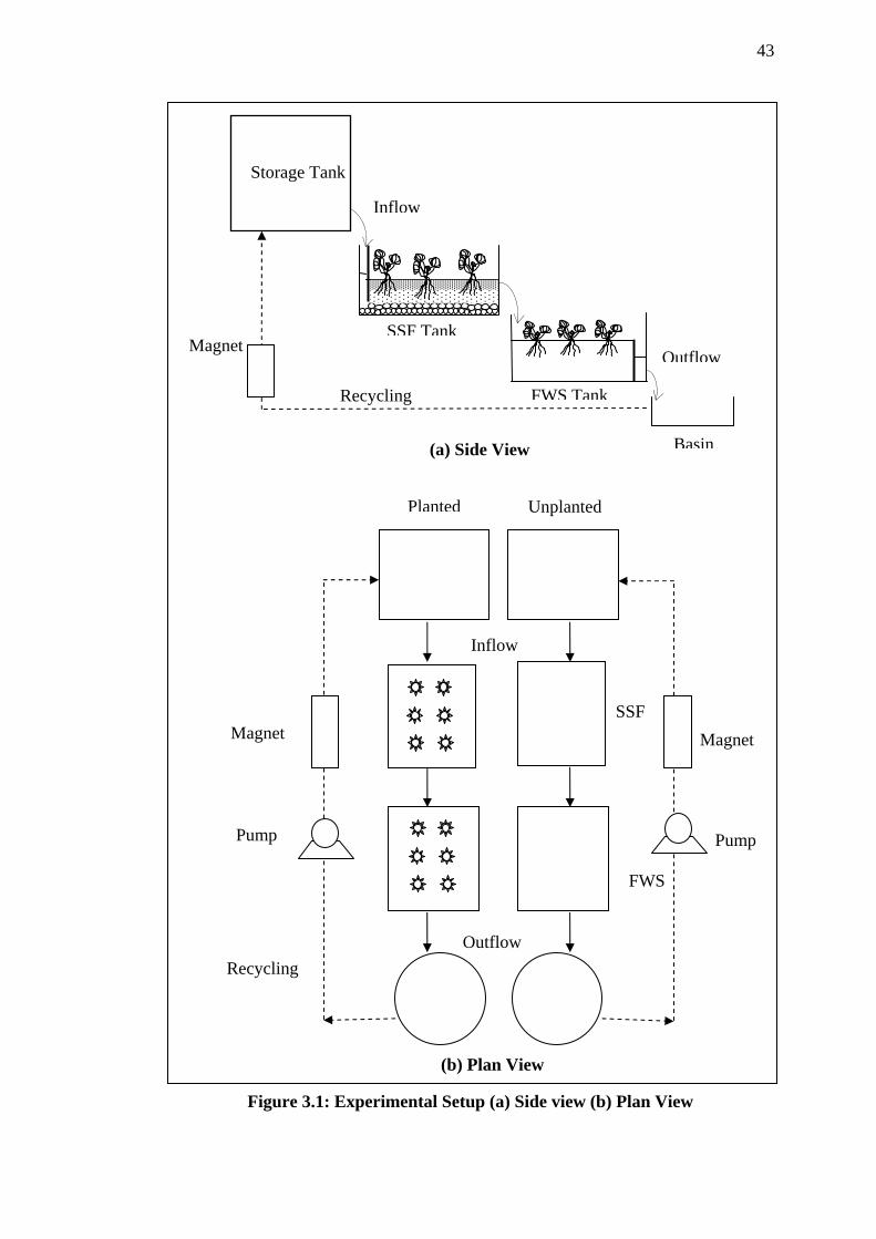
43
Storage Tank
SSF Tank
FWS TankRecycling
Inflow
OutflowMagnet
(a) Side View Basin
Inflow
SSF
FWS
Outflow
Planted Unplanted
Recycling
Pump
Magnet Magnet
Pump
(b) Plan View
Figure 3.1: Experimental Setup (a) Side view (b) Plan View
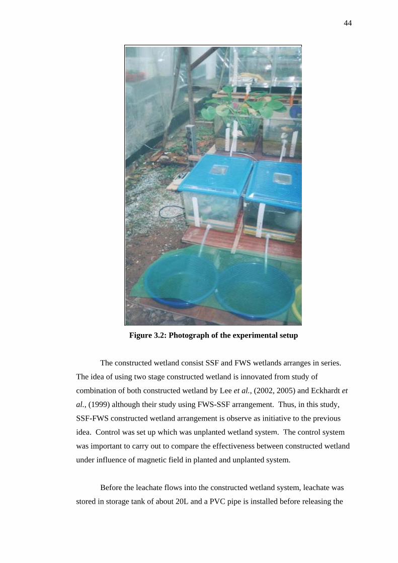
44
Figure 3.2: Photograph of the experimental setup
The constructed wetland consist SSF and FWS wetlands arranges in series.
The idea of using two stage constructed wetland is innovated from study of
combination of both constructed wetland by Lee et al., (2002, 2005) and Eckhardt et
al., (1999) although their study using FWS-SSF arrangement. Thus, in this study,
SSF-FWS constructed wetland arrangement is observe as initiative to the previous
idea. Control was set up which was unplanted wetland system. The control system
was important to carry out to compare the effectiveness between constructed wetland
under influence of magnetic field in planted and unplanted system.
SSF Tank Magnet
Before the leachate flows into the constructed wetland system, leachate was
stored in storage tank of about 20L and a PVC pipe is installed before releasing the Settling basin

45
flow into the tanks. A pipe use to control the flow rate of the leachate flow into the
wetland which design to adjust the hydraulic retention time (HRT) required. The
flow rate use in this study is 15mL/min and the hydraulic retention time (HRT) for
overall system is about 13.3 hour for one experiment run. For each concentration,
the experiment runs for three weeks and use different plants, media and leachate
samples. The leachate samples will continuously return back to the storage tank
from the settling tank.
This study was focussed on the ability of magnetic field in removing nutrients
and heavy metals in leachate. 0.55 Tesla magnet strength which is the optimum
performance of magnetic treatment used in this experiment. Six set of magnet were
used as shows in Figure 3.3. The experiments were used circulation system where
the samples were circulating through the magnetic field for duration of 4 hours. The
sample of leachate will be pre-treated with magnetic field for 4 hours before inflow
in wetlands system.
Figure 3.3: Arrangement of magnet set (Johan, 2003)
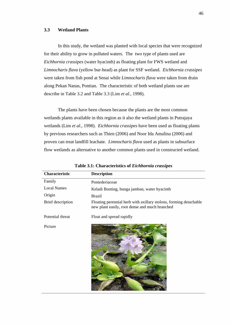
46
3.3 Wetland Plants
In this study, the wetland was planted with local species that were recognized
for their ability to grow in polluted waters. The two type of plants used are
Eichhornia crassipes (water hyacinth) as floating plant for FWS wetland and
Limnocharis flava (yellow bur-head) as plant for SSF wetland. Eichhornia crassipes
were taken from fish pond at Senai while Limnocharis flava were taken from drain
along Pekan Nanas, Pontian. The characteristic of both wetland plants use are
describe in Table 3.2 and Table 3.3 (Lim et al., 1998).
The plants have been chosen because the plants are the most common
wetlands plants available in this region as it also the wetland plants in Putrajaya
wetlands (Lim et al., 1998). Eichhornia crassipes have been used as floating plants
by previous researchers such as Thien (2006) and Noor Ida Amalina (2006) and
proven can treat landfill leachate. Limnocharis flava used as plants in subsurface
flow wetlands as alternative to another common plants used in constructed wetland.
Table 3.1: Characteristics of Eichhornia crassipes
Characteristic Description
Family Pontederiaceae Local Names Keladi Bunting, bunga jamban, water hyacinth Origin Brazil Brief description Floating perennial herb with axillary stolons, forming detachable
new plant easily, root dense and much branched
Potential threat Float and spread rapidly
Picture

47
Table 3.2: Characteristics of Limnocharis flava
Characteristic Description
Family Butomaceae
Local Names Yellow Bur-head, sawah-flower rush, sawah-lettuce, velvetleaf, Jinjir
Origin Tropical America
Brief description Perennial, erect, robust marsh herb, rooting in mud and strongly tillering, 20-100 cm tall
Potential threat Common in ditches and shallow river, has potential of taking over from targeted species especially in shallow marsh
Picture
3.4 Media
The media used in the SSF constructed wetlands in this study consisted of a
layer of gravel with 15-20 mm diameter (2 cm), providing a porosity of 45%
followed by a layer of a mixture of sand and soil with ratio (2:1) (5 cm)and a layer of
soil at the surface (2 cm) creating a 9 cm media depth. The media are within 1 cm
below from the top water level to allow overflowing. According to Pant et al.,
(2001) inexpensive material such as sand can effectively remove phosphorus through
sorption and their usage as root bed media can increase the efficiency of constructed
wetland especially in removing phosphorus.
48
3.5 Sampling and Analysis
After leachate collected from landfill, the initial concentration of the leachate
samples measured as comparison to the result and to examine a performance of
leachate treatment. The leachate samples were taken two times a week from the
effluent of the SSF wetland and FWS wetland and analyzed. These samples were
analyses for suspended solid (SS), ammonia nitrogen (NH3-N), ortho-phosphate
phosphorus (PO4-P), iron (Fe) and Manganse (Mn). The FWS tanks are aerated to
increase the release of Fe and Mn. All the analytical measurement carried out
according to Standard Method (APHA, 2002). The nutrients and heavy metals are
analyses using HACH DR4000 Spectrophotometer while SS are analyses using
APHA procedure. The procedures for leachate samples analysis were listed as
follow:
(a) Ammonia-Nitrogen (NH3-N)
NH3-N analysis was conducted according to Standard Method APHA 4500-
NH3 by using HACH DR4000 with 8039- Nessler Method procedure.
(b) Phosphorus (PO43-)
PO43- analysis was conducted according to Standard Method APHA 4500- P
(C) using HACH DR4000 with 8114 - Molybdovanadate Reagent procedure.
(c) Total Iron (Fe)
Total iron analysis was conducted according to Standard Method APHA
3500-Fe (B) using HACH DR4000 with 8147- Ferrover Iron Reagent procedure.
(d) Manganese (Mn)
Manganese analysis was conducted according to Standard Method APHA
3500-Mn (B) using HACH DR4000 with 8149- Manganese PAN Method procedure.
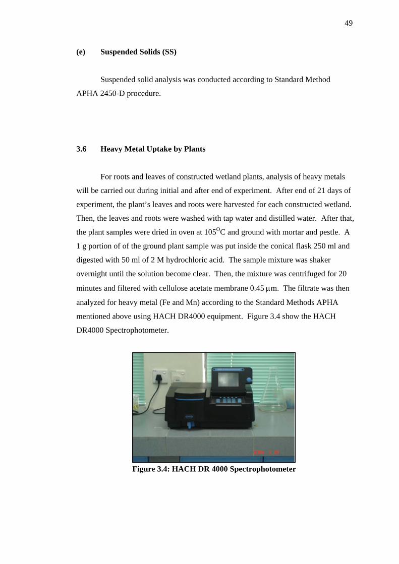
49
(e) Suspended Solids (SS)
Suspended solid analysis was conducted according to Standard Method
APHA 2450-D procedure.
3.6 Heavy Metal Uptake by Plants
For roots and leaves of constructed wetland plants, analysis of heavy metals
will be carried out during initial and after end of experiment. After end of 21 days of
experiment, the plant’s leaves and roots were harvested for each constructed wetland.
Then, the leaves and roots were washed with tap water and distilled water. After that,
the plant samples were dried in oven at 105OC and ground with mortar and pestle. A
1 g portion of of the ground plant sample was put inside the conical flask 250 ml and
digested with 50 ml of 2 M hydrochloric acid. The sample mixture was shaker
overnight until the solution become clear. Then, the mixture was centrifuged for 20
minutes and filtered with cellulose acetate membrane 0.45 μm. The filtrate was then
analyzed for heavy metal (Fe and Mn) according to the Standard Methods APHA
mentioned above using HACH DR4000 equipment. Figure 3.4 show the HACH
DR4000 Spectrophotometer.
Figure 3.4: HACH DR 4000 Spectrophotometer
CHAPTER 4
RESULT AND DISCUSSION
4.1 Introduction
In this chapter, the results obtained from the lab-scale subsurface flow- free
water surface flow (SSF-FWS) constructed wetlands under influence of magnetic
field observation and experiment will be discussed in details. Afterward, all data will
be carried out in graphical approach to evaluation analysis processes. The
experiments were conducted from July to August 2006. The experiments were
carried out twice and each experiment runs for 21 days to get the raw data. Sampling
was done once for every 3 days. The analysis considers the average results of
removal efficiency and performance of planted and unplanted (control) constructed
wetland with magnetic field in leachate treatment.
The performances of SSF-FWS constructed wetland system were evaluated
using the first-order plug flow kinetic model:
kteCCo −= (4.1)
Where C = influent pollutant concentration, mg/L; Co = effluent pollutant
concentration, mg/l; t = time, day; k = first-order removal rate constant, day-1. Many
researchers have applied the first-order reaction model for removal of ammonium,
nitrate, total nitrogen, and phosphate in FWS and SSF wetlands (Reed et al., 1995;
Kadlec and Knight, 1996).

51
It is not suitable to compare the performance data between the SSF and FWS
wetlands in such series combination system in which the concentration of influent to
each wetland were considerably different. This is because low pollutant loads
received by the second wetland (in this study, FWS) thereby kinetically limiting the
removal efficiency.
Table 4.1 shows the initial concentration of leachate taken from Pasir Gudang
Sanitary Landfill for water quality parameter after sampling from the raw untreated
landfill leachate pond. The analysis of initial concentration are analysed for
ammonia nitrogen, nitrate, orthophosphate, iron, manganese and suspended solid.
The constituents in the leachate be varies depending on waste composition and
weather.
Table 4.1: Initial quality of leachate
Parameter Concentration range (mg/L)
Ammonia nitrogen (NH3-N) 42.25-104.6 Nitrate nitrogen (NO3-N) 10.0-17.5 Orthphosphate (PO4
3-) 43.75-55.4 Ferum (Fe) 17.2-19.4 Manganese (Mn) 0.47-0.52 Suspended Solid (SS) 140-160
Table 4.2 shows the comparison of removal efficiency of SSF-FWS
constructed wetland between planted and unplanted as a control in treating landfill
leachate under influent of magnetic field. Analysis of variance (ANOVA) has been
used to reveal significant differences between planted and control constructed
wetland. Statistical significance differences were tested at P≤0.05 (95% levels of
significance).
From the table, it shows that planted system give the higher percentage
removal for all parameters that had been analyzed. The removals for planted
constructed wetland exceed 90% for all parameter. Those result shows that the
constructed wetland system under influence of magnetic field can reduce pollutant
concentration. According to Lin et al., (2002), improved pollutant removal can be
achieved by combining different types of constructed wetlands in series through a
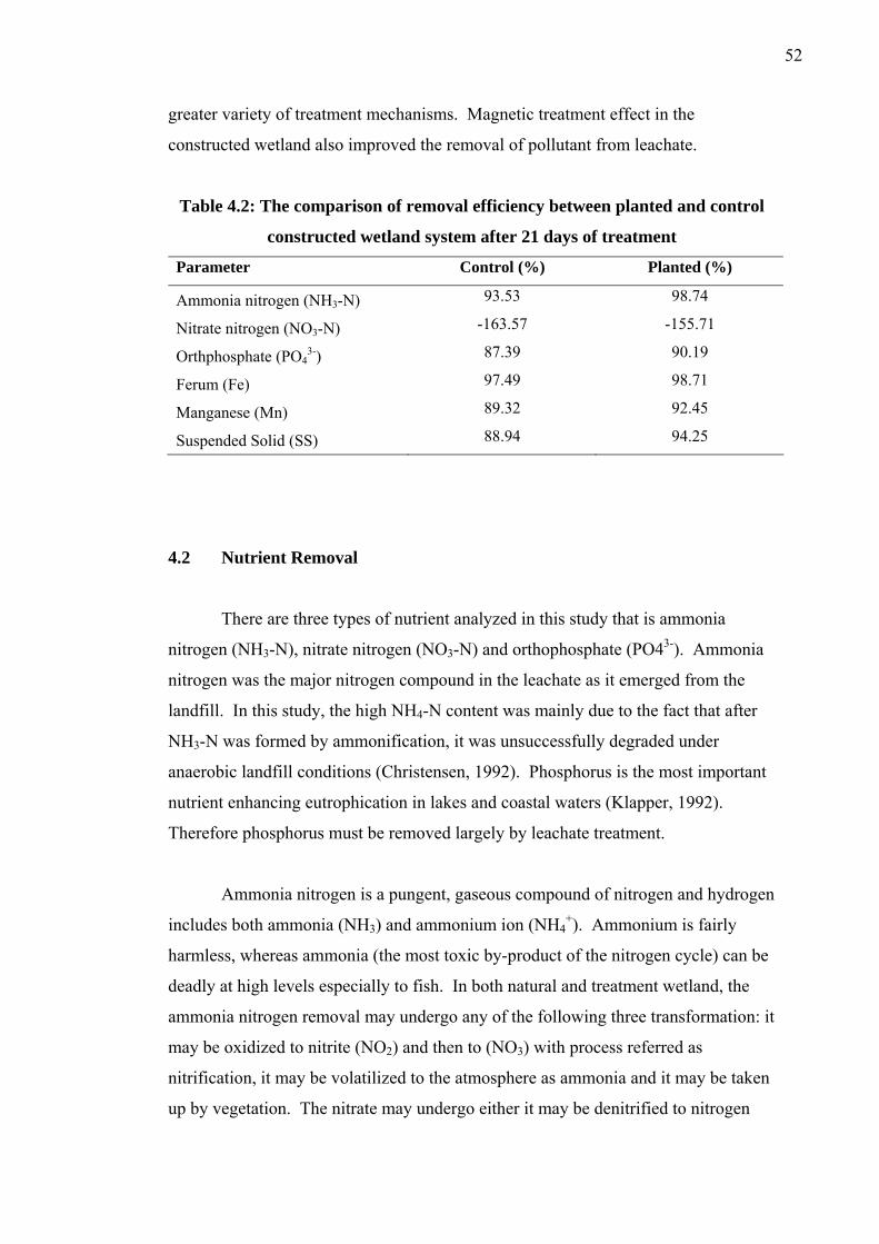
52
greater variety of treatment mechanisms. Magnetic treatment effect in the
constructed wetland also improved the removal of pollutant from leachate.
Table 4.2: The comparison of removal efficiency between planted and control
constructed wetland system after 21 days of treatment
Parameter Control (%) Planted (%)
Ammonia nitrogen (NH3-N) 93.53 98.74
Nitrate nitrogen (NO3-N) -163.57 -155.71
Orthphosphate (PO43-) 87.39 90.19
Ferum (Fe) 97.49 98.71
Manganese (Mn) 89.32 92.45
Suspended Solid (SS) 88.94 94.25
4.2 Nutrient Removal
There are three types of nutrient analyzed in this study that is ammonia
nitrogen (NH3-N), nitrate nitrogen (NO3-N) and orthophosphate (PO43-). Ammonia
nitrogen was the major nitrogen compound in the leachate as it emerged from the
landfill. In this study, the high NH4-N content was mainly due to the fact that after
NH3-N was formed by ammonification, it was unsuccessfully degraded under
anaerobic landfill conditions (Christensen, 1992). Phosphorus is the most important
nutrient enhancing eutrophication in lakes and coastal waters (Klapper, 1992).
Therefore phosphorus must be removed largely by leachate treatment.
Ammonia nitrogen is a pungent, gaseous compound of nitrogen and hydrogen
includes both ammonia (NH3) and ammonium ion (NH4+). Ammonium is fairly
harmless, whereas ammonia (the most toxic by-product of the nitrogen cycle) can be
deadly at high levels especially to fish. In both natural and treatment wetland, the
ammonia nitrogen removal may undergo any of the following three transformation: it
may be oxidized to nitrite (NO2) and then to (NO3) with process referred as
nitrification, it may be volatilized to the atmosphere as ammonia and it may be taken
up by vegetation. The nitrate may undergo either it may be denitrified to nitrogen
53
(N2) gas in the absence of oxygen or it may be taken up by vegetation (Mitsh and
Gosselink, 1986).
Phosphorus is an essential macronutrient that is limiting factor to plant
growth. It is essential to all life as nucleic acids and a universal energy molecule
(Lee and Lee, 2001). In excess, phosphorus triggers a eutrophic condition which
involves the profile growth of algal and other aquatic plants. Algal growth can have
lethal impacts on aquatic life and at high concentrations can be toxic in it self. In
waters, phosphorus is often biologically unavailable as it binds readily to particles.
Soluble phosphorus which is available for uptake is called orthophosphate.
According to Brix (1997) macrophytes play significant roles within a
constructed wetlands system and they are an integral part in nutrient cycling.
Macrophytic plants encourage the assimilation and breakdown of nutrients within a
wetlands system. They have the ability not only to bind high amounts of nutrients
within their system, but also to create an environment conducive to decreasing
nutrients. Macrophytes provide surface area on their stems and leaves, which is
necessary for microbial growth. The roots provide a structure for microorganisms to
perform the processes necessary for transformation of nutrients. Moreover, roots not
only provide a place for microbes but also serve to decrease erosion (soil protector)
and increase the levels of oxygen, which provides for the oxidation of toxic
substances like ammonia and nitrites.
4.2.1 Ammonia Removal
Influent of ammonia nitrogen (NH3-N) ranged approximately 42.25 to 104.6
mg/L while the effluents in each system ranged from 3.0 to 6.1 mg/L (control) and
0.68 to 0.95 m/L (planted). Figure 4.1 shows the removal efficiency of the planted
and control constructed wetland system in 21 days of treatment. In the end of study,
the planted constructed wetland system achieved highest removal for NH3-N with
98.74% while 93.53% for control system. Table 4.3 illustrates the correlation
between removal efficiency with time of treatment with correlation coefficient (r2)

54
from 0.89 to 0.92. This shows that removal efficiency percentages are increases with
increase time of treatment.
0
1020
3040
50
6070
8090
100
0 3 6 9 12 15 18 21Time (days)
% R
emov
al
ControlPlanted
Figure 4.1: Removal efficiency of NH3-N in control and planted
constructed wetland system with magnetic field
Table 4.3: Correlation between removal efficiency with time of treatment
for NH3-N
System Equation Correlation coefficient, r2
Control y = 1.3717x + 65.77 0.9128
Planted y = 1.7099x + 65.057 0.8948
Performance of the SSF-FWS constructed wetland system on NH3-N removal
in 21 days of experiment was presented in Figure 4.2. Ammonia reduction followed
first-order kinetics, with removal rate constants of 0.2864/day for the planted system
while 0.2578/day for control system. From ANOVA test, there is insignificant
different (P≥0.05) between planted and control system in remove NH3-N.
The insignificant different between both system was because the nitrification
process was taking place actively in the wetland system. Although, planted
constructed wetland still has greater removal efficiency of NH3-N because of the
plant uptake and the roots of the plants can supply more oxygen for the nitrifying
bacteria where ammonia was converted to nitrite and then nitrate.
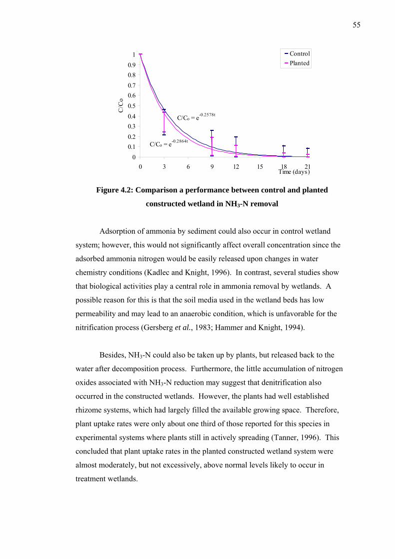
55
C/Co = e-0.2578t
C/Co = e-0.2864t
00.10.20.30.40.50.60.70.80.9
1
0 3 6 9 12 15 18 2Time (days)
C/C
o
1
ControlPlanted
Figure 4.2: Comparison a performance between control and planted
constructed wetland in NH3-N removal
Adsorption of ammonia by sediment could also occur in control wetland
system; however, this would not significantly affect overall concentration since the
adsorbed ammonia nitrogen would be easily released upon changes in water
chemistry conditions (Kadlec and Knight, 1996). In contrast, several studies show
that biological activities play a central role in ammonia removal by wetlands. A
possible reason for this is that the soil media used in the wetland beds has low
permeability and may lead to an anaerobic condition, which is unfavorable for the
nitrification process (Gersberg et al., 1983; Hammer and Knight, 1994).
Besides, NH3-N could also be taken up by plants, but released back to the
water after decomposition process. Furthermore, the little accumulation of nitrogen
oxides associated with NH3-N reduction may suggest that denitrification also
occurred in the constructed wetlands. However, the plants had well established
rhizome systems, which had largely filled the available growing space. Therefore,
plant uptake rates were only about one third of those reported for this species in
experimental systems where plants still in actively spreading (Tanner, 1996). This
concluded that plant uptake rates in the planted constructed wetland system were
almost moderately, but not excessively, above normal levels likely to occur in
treatment wetlands.
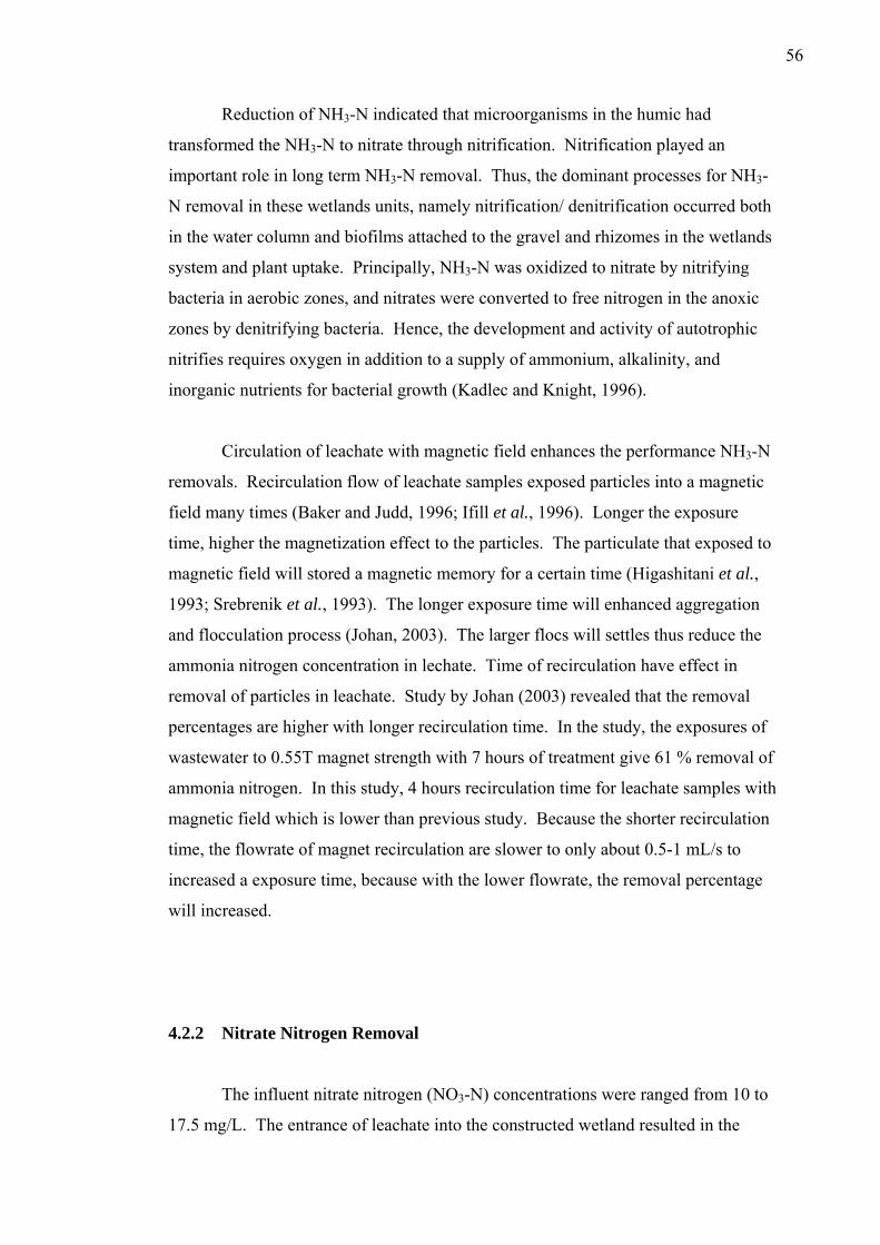
56
Reduction of NH3-N indicated that microorganisms in the humic had
transformed the NH3-N to nitrate through nitrification. Nitrification played an
important role in long term NH3-N removal. Thus, the dominant processes for NH3-
N removal in these wetlands units, namely nitrification/ denitrification occurred both
in the water column and biofilms attached to the gravel and rhizomes in the wetlands
system and plant uptake. Principally, NH3-N was oxidized to nitrate by nitrifying
bacteria in aerobic zones, and nitrates were converted to free nitrogen in the anoxic
zones by denitrifying bacteria. Hence, the development and activity of autotrophic
nitrifies requires oxygen in addition to a supply of ammonium, alkalinity, and
inorganic nutrients for bacterial growth (Kadlec and Knight, 1996).
Circulation of leachate with magnetic field enhances the performance NH3-N
removals. Recirculation flow of leachate samples exposed particles into a magnetic
field many times (Baker and Judd, 1996; Ifill et al., 1996). Longer the exposure
time, higher the magnetization effect to the particles. The particulate that exposed to
magnetic field will stored a magnetic memory for a certain time (Higashitani et al.,
1993; Srebrenik et al., 1993). The longer exposure time will enhanced aggregation
and flocculation process (Johan, 2003). The larger flocs will settles thus reduce the
ammonia nitrogen concentration in lechate. Time of recirculation have effect in
removal of particles in leachate. Study by Johan (2003) revealed that the removal
percentages are higher with longer recirculation time. In the study, the exposures of
wastewater to 0.55T magnet strength with 7 hours of treatment give 61 % removal of
ammonia nitrogen. In this study, 4 hours recirculation time for leachate samples with
magnetic field which is lower than previous study. Because the shorter recirculation
time, the flowrate of magnet recirculation are slower to only about 0.5-1 mL/s to
increased a exposure time, because with the lower flowrate, the removal percentage
will increased.
4.2.2 Nitrate Nitrogen Removal
The influent nitrate nitrogen (NO3-N) concentrations were ranged from 10 to
17.5 mg/L. The entrance of leachate into the constructed wetland resulted in the
57
increase in nitrate concentrations and in the end of 21 days of treatment the nitrate
effluent concentration range from 27 to 45 mg/L for control system and 26 to 44
mg/L for planted system. The removal efficiency was negative due to the increase in
effluent concentrations with regard to the influent ones. From ANOVA analysis of
the removal efficiency comparison between planted and control system, there is
insignificant different for both system in removing NO3-N where P = 0.814 (P>0.05).
The performance of NO3-N removal does not follow the first order plug flow kinetic
model. So, the graph of C/Co cannot be plotted.
Figure 4.3 shows the removal efficiency of NO3-N throughout the duration of
study. During the initial startup of the experiment, the nitrate level levels in the
effluent remained low, suggesting that any conversion of ammonia to this form by
nitrification was either rapidly converted to nitrogen gas by denitrification or taken
up by plants. The increasing ability of the planted system at the beginning of
experiment to remove NO3-N is relatively similar to unplanted controls. From the
graph, only one day of treatment is sufficient to remove NO3-N where the removal
up to 95 percent. In the three days of treatment the removal efficiency only achieved
50 percent of removal.
The negative removal efficiency after 9 days of treatment suggest that the
media substrate itself was leaching NO3-N in both control and planted constructed
wetland system. Another reason for the high NO3-N concentration in the effluent
may be because conditions in the soil were favoring nitrification resulting in a
decrease in NH3-N levels but increase in NO3-N content in the soil solution. The
negative removal efficiency also reported by Bethan (1996). The result was
contradicted to local researches in nitrate removal in constructed such as Ain Nihla
(2006), Nazaitul Shila (2006), Noor Ida Amalina (2006) and Thien (2006). The
mechanism that increasing the NO3-N concentration and contribute to negative
removal is unknown.
Other studies on constructed wetlands have indicated such low efficiency
conversion of ammonia to nitrite (Hammer and Knight, 1994; Brown and Reed,
1994), but Tanner (1999) reported a high ammonia removal rate by nitrification
followed by denitrification. Hence, the denitrification process in the wetland became
58
the limiting step in the removal process. High NO3-N concentration in effluent is
also may be due to NO3-N is rapidly take up by plant roots (Reddy and Smith, 1987).
0
10
20
30
40
50
60
70
80
90
100
0 3 6 9 12 15 18 21
Time (days)
% R
emov
al
ControlPlanted
Figure 4.3: Removal efficiency for NO3-N, comparison between control and
planted constructed wetland with magnetic field
The circulation of leachate samples to magnet increased NO3-N removal via
sedimentation. The magnetic field will enhance particles movement and aggregation
process to produce large flocs. The large and heavy flocs were settled to the
sediments. The magnetic field strength increases the magnetic force, which
subsequently enhances the removal efficiency.
4.2.3 Orthophosphate Removal
Influent of orthophosphate (PO43-) ranged approximately 43.75 to 55.4 mg/L
while the effluents in each system ranged from 6.15 to 6.18 mg/L (control) and 3.9 to
5.5 m/L (planted). Figure 4.4 shows the PO43- removal efficiency of control and
planted constructed wetland. The constructed wetland system achieved greatest
PO43-removal for planted system with 90.19% while 87.39% for control system in
the end of treatment duration.
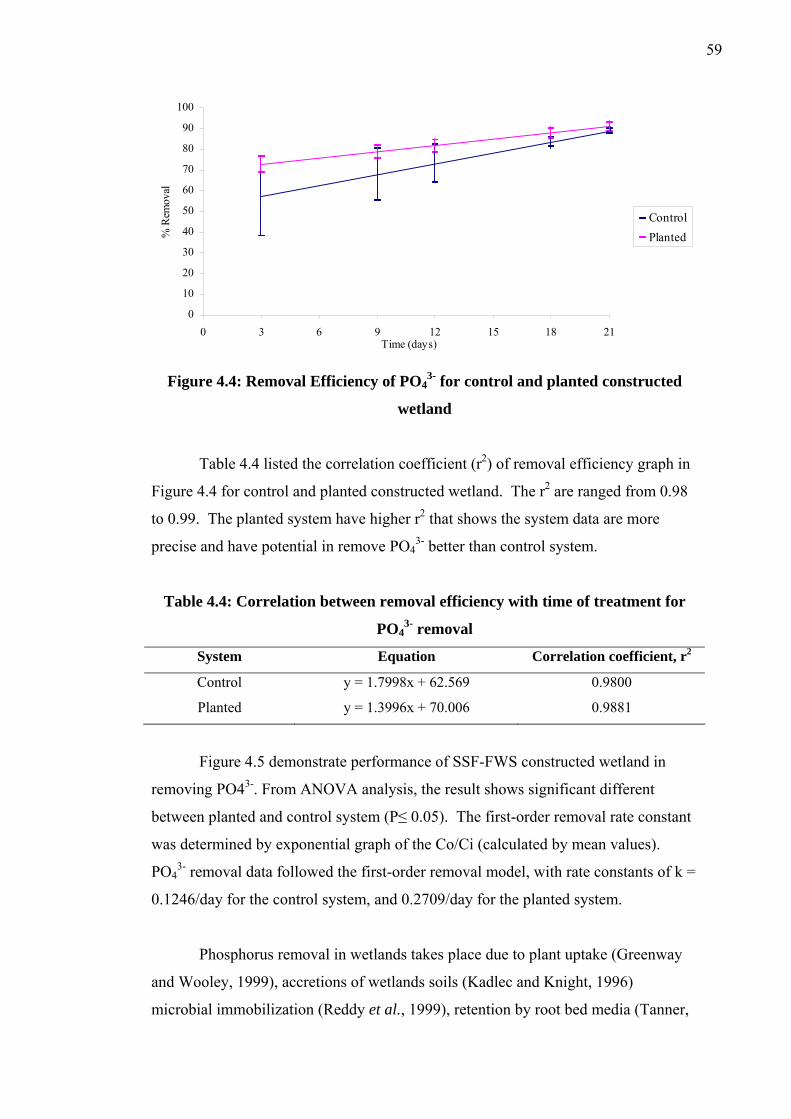
59
0
10
20
30
40
50
60
70
80
90
100
0 3 6 9 12 15 18 21Time (days)
% R
emov
al
ControlPlanted
Figure 4.4: Removal Efficiency of PO4
3- for control and planted constructed
wetland
Table 4.4 listed the correlation coefficient (r2) of removal efficiency graph in
Figure 4.4 for control and planted constructed wetland. The r2 are ranged from 0.98
to 0.99. The planted system have higher r2 that shows the system data are more
precise and have potential in remove PO43- better than control system.
Table 4.4: Correlation between removal efficiency with time of treatment for
PO43- removal
System Equation Correlation coefficient, r2
Control y = 1.7998x + 62.569 0.9800
Planted y = 1.3996x + 70.006 0.9881
Figure 4.5 demonstrate performance of SSF-FWS constructed wetland in
removing PO43-. From ANOVA analysis, the result shows significant different
between planted and control system (P≤ 0.05). The first-order removal rate constant
was determined by exponential graph of the Co/Ci (calculated by mean values).
PO43- removal data followed the first-order removal model, with rate constants of k =
0.1246/day for the control system, and 0.2709/day for the planted system.
Phosphorus removal in wetlands takes place due to plant uptake (Greenway
and Wooley, 1999), accretions of wetlands soils (Kadlec and Knight, 1996)
microbial immobilization (Reddy et al., 1999), retention by root bed media (Tanner,
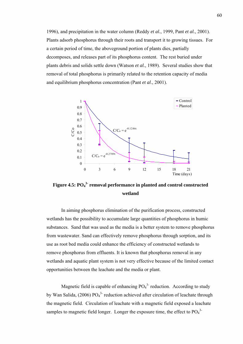
60
1996), and precipitation in the water column (Reddy et al., 1999, Pant et al., 2001).
Plants adsorb phosphorus through their roots and transport it to growing tissues. For
a certain period of time, the aboveground portion of plants dies, partially
decomposes, and releases part of its phosphorus content. The rest buried under
plants debris and solids settle down (Watson et al., 1989). Several studies show that
removal of total phosphorus is primarily related to the retention capacity of media
and equilibrium phosphorus concentration (Pant et al., 2001).
C/Co = e-0.1246t
C/Co = e-0.2709t
00.10.20.30.40.50.60.70.80.9
1
0 3 6 9 12 15 18 21Time (days)
C/C
o
ControlPlanted
Figure 4.5: PO4
3- removal performance in planted and control constructed
wetland
In aiming phosphorus elimination of the purification process, constructed
wetlands has the possibility to accumulate large quantities of phosphorus in humic
substances. Sand that was used as the media is a better system to remove phosphorus
from wastewater. Sand can effectively remove phosphorus through sorption, and its
use as root bed media could enhance the efficiency of constructed wetlands to
remove phosphorus from effluents. It is known that phosphorus removal in any
wetlands and aquatic plant system is not very effective because of the limited contact
opportunities between the leachate and the media or plant.
Magnetic field is capable of enhancing PO43- reduction. According to study
by Wan Salida, (2006) PO43- reduction achieved after circulation of leachate through
the magnetic field. Circulation of leachate with a magnetic field exposed a leachate
samples to magnetic field longer. Longer the exposure time, the effect to PO43-

61
removal was enhanced. Exposed of charged particles including PO43- ion to
magnetic field would electrically contribute to a greater ionic charged and contribute
to extra energy. This energy will make the charged particles to vibrate excessively.
Thus more particles are colliding among themselves (Johan et al., 2004). This
reaction contributes to additional number of ions (positive and negative charge),
which consequently creates a natural magnetic attraction between the opposite
charged particles. Particles are attracted and agglomerated (Johan, 2003).
4.3 Heavy Metal Removal
Metals are frequently mentioned in leachate. The metals which are most
commonly present in landfill leachate at high concentrations are iron and manganese
in their reduced forms (Fe2+ and Mn2+), which are the two contaminant of concern in
this study. Wetlands system was often considered sinks for contaminants, and there
are many cases in which wetland plants were utilized for removal of pollutants,
including metals. Metals are removed in treatment wetlands by three major
mechanisms (Kadlec and Knight, 1996) that are binding to soil, sediments,
particulates and soluble organic by cation exhange and chelation, precipitation as
insoluble salts, principally sulfides and oxyhydroxides; and uptake by plants,
including algae and by bacteria .
The wetland plant is a crucial part in metal removal by actively facilitating
the physiochemical reactions responsible for majority of their removal. This
supporting activity includes physical trapping and filtration of particulates,
facilitation of sedimentation and sediment stabilization. Iron is an essential
micronutrient element required by both plants and wildlife at significant
concentrations, as it is a vital part of metabolic enzyme formation and the oxygen
transport mechanism in the plant tissues and the hemoglobin of vertebrate and
invertebrate animals (King et al., 1992). Iron also occurs as one of the principle
chemical constituent in water (Mason, 1998). Manganese is an essential
micronutrient forming a vital part of the enzyme systems that metabolized protein
and energy in all animals.
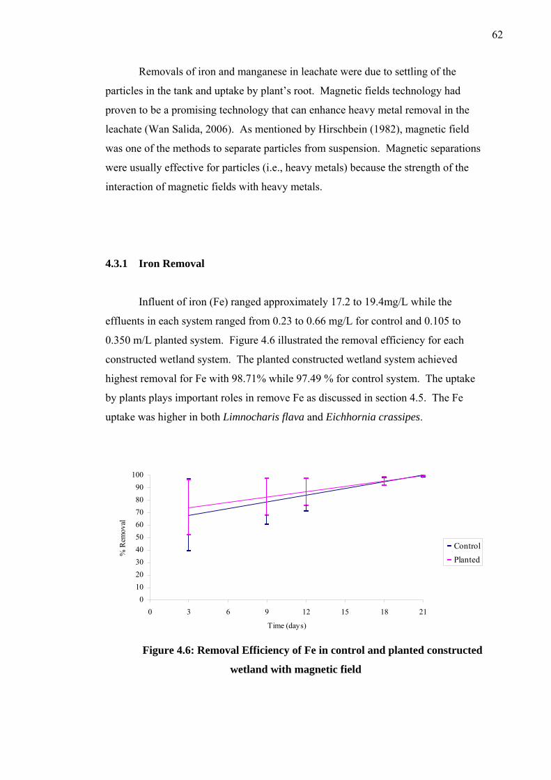
62
Removals of iron and manganese in leachate were due to settling of the
particles in the tank and uptake by plant’s root. Magnetic fields technology had
proven to be a promising technology that can enhance heavy metal removal in the
leachate (Wan Salida, 2006). As mentioned by Hirschbein (1982), magnetic field
was one of the methods to separate particles from suspension. Magnetic separations
were usually effective for particles (i.e., heavy metals) because the strength of the
interaction of magnetic fields with heavy metals.
4.3.1 Iron Removal
Influent of iron (Fe) ranged approximately 17.2 to 19.4mg/L while the
effluents in each system ranged from 0.23 to 0.66 mg/L for control and 0.105 to
0.350 m/L planted system. Figure 4.6 illustrated the removal efficiency for each
constructed wetland system. The planted constructed wetland system achieved
highest removal for Fe with 98.71% while 97.49 % for control system. The uptake
by plants plays important roles in remove Fe as discussed in section 4.5. The Fe
uptake was higher in both Limnocharis flava and Eichhornia crassipes.
0102030405060708090
100
0 3 6 9 12 15 18 21
Time (days)
% R
emov
al
ControlPlanted
Figure 4.6: Removal Efficiency of Fe in control and planted constructed
wetland with magnetic field
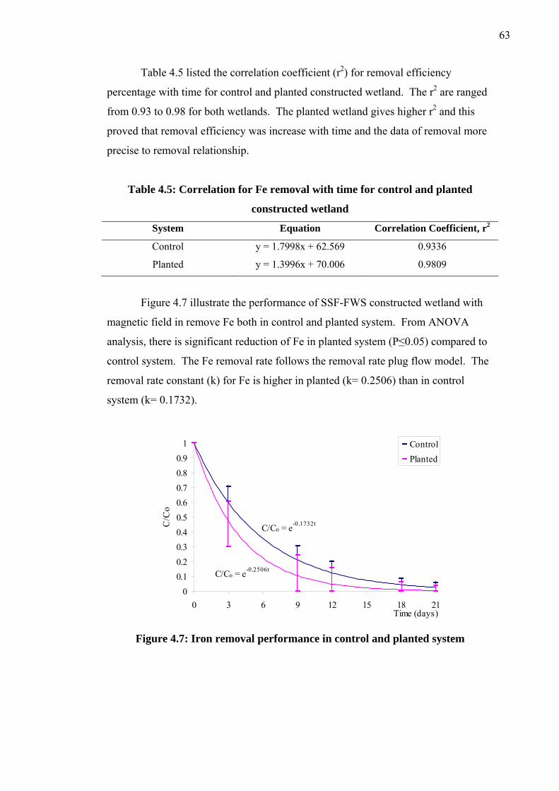
63
Table 4.5 listed the correlation coefficient (r2) for removal efficiency
percentage with time for control and planted constructed wetland. The r2 are ranged
from 0.93 to 0.98 for both wetlands. The planted wetland gives higher r2 and this
proved that removal efficiency was increase with time and the data of removal more
precise to removal relationship.
Table 4.5: Correlation for Fe removal with time for control and planted
constructed wetland
System Equation Correlation Coefficient, r2
Control y = 1.7998x + 62.569 0.9336
Planted y = 1.3996x + 70.006 0.9809
Figure 4.7 illustrate the performance of SSF-FWS constructed wetland with
magnetic field in remove Fe both in control and planted system. From ANOVA
analysis, there is significant reduction of Fe in planted system (P≤0.05) compared to
control system. The Fe removal rate follows the removal rate plug flow model. The
removal rate constant (k) for Fe is higher in planted (k= 0.2506) than in control
system (k= 0.1732).
C/Co = e-0.1732t
C/Co = e-0.2506t
00.10.20.30.40.50.60.70.80.9
1
0 3 6 9 12 15 18 21Time (days)
C/C
o
ControlPlanted
Figure 4.7: Iron removal performance in control and planted system
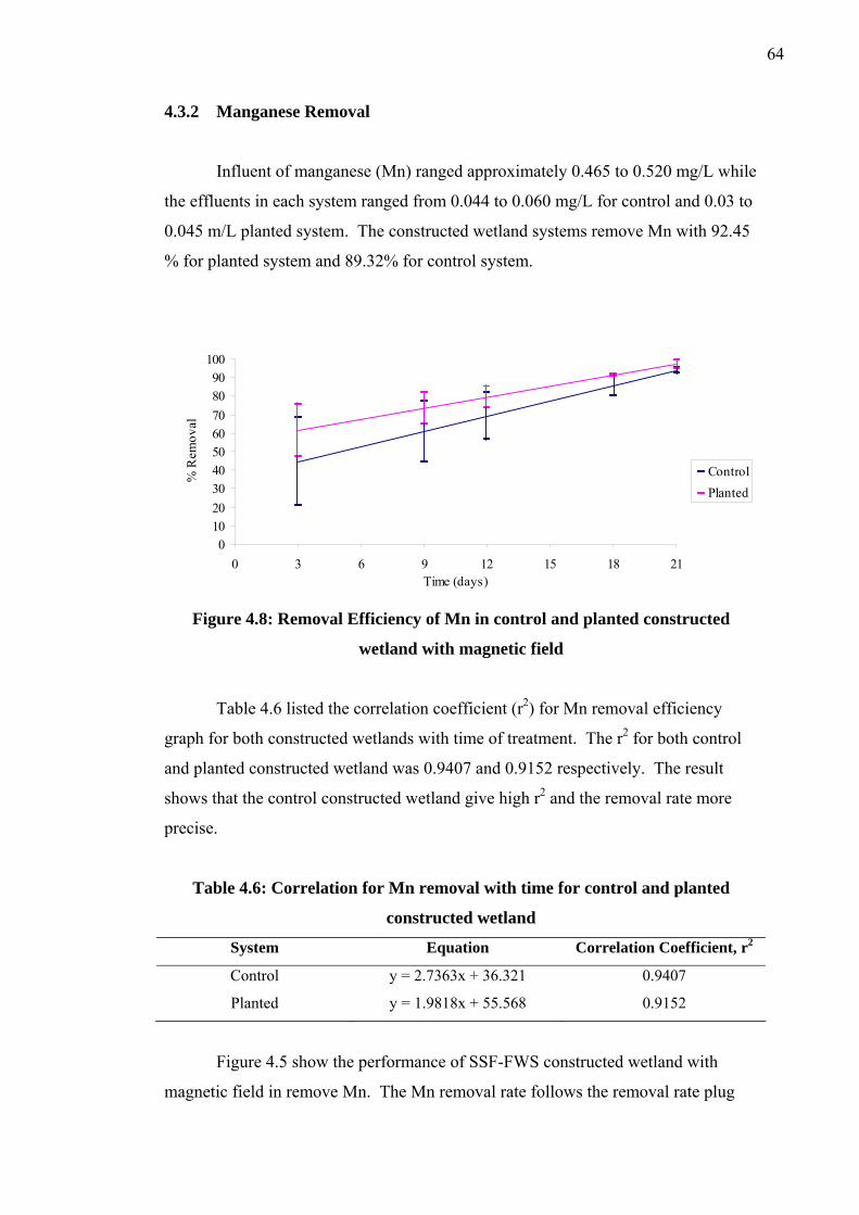
64
4.3.2 Manganese Removal
Influent of manganese (Mn) ranged approximately 0.465 to 0.520 mg/L while
the effluents in each system ranged from 0.044 to 0.060 mg/L for control and 0.03 to
0.045 m/L planted system. The constructed wetland systems remove Mn with 92.45
% for planted system and 89.32% for control system.
0102030405060708090
100
0 3 6 9 12 15 18 21Time (days)
% R
emov
al
ControlPlanted
Figure 4.8: Removal Efficiency of Mn in control and planted constructed
wetland with magnetic field
Table 4.6 listed the correlation coefficient (r2) for Mn removal efficiency
graph for both constructed wetlands with time of treatment. The r2 for both control
and planted constructed wetland was 0.9407 and 0.9152 respectively. The result
shows that the control constructed wetland give high r2 and the removal rate more
precise.
Table 4.6: Correlation for Mn removal with time for control and planted
constructed wetland
System Equation Correlation Coefficient, r2
Control y = 2.7363x + 36.321 0.9407
Planted y = 1.9818x + 55.568 0.9152
Figure 4.5 show the performance of SSF-FWS constructed wetland with
magnetic field in remove Mn. The Mn removal rate follows the removal rate plug
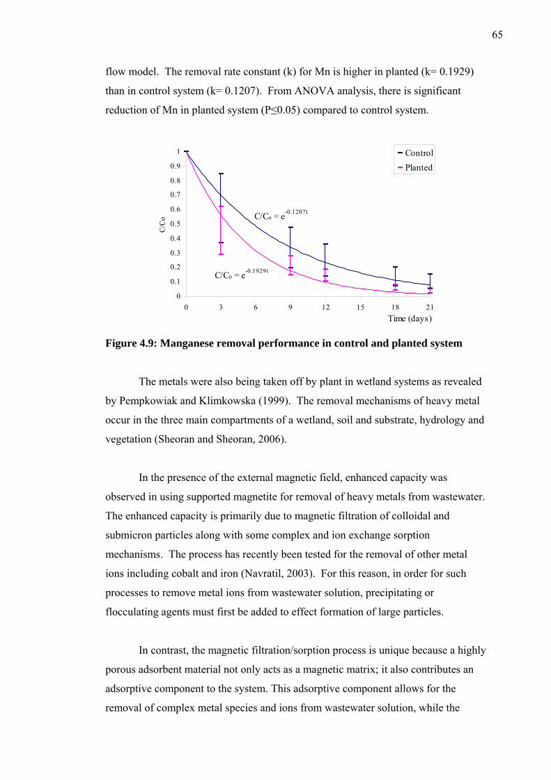
65
flow model. The removal rate constant (k) for Mn is higher in planted (k= 0.1929)
than in control system (k= 0.1207). From ANOVA analysis, there is significant
reduction of Mn in planted system (P≤0.05) compared to control system.
C/Co = e-0.1207t
C/Co = e-0.1929t
0
0.1
0.2
0.3
0.4
0.5
0.6
0.7
0.8
0.9
1
0 3 6 9 12 15 18Time (days)
C/Co
21
ControlPlanted
Figure 4.9: Manganese removal performance in control and planted system
The metals were also being taken off by plant in wetland systems as revealed
by Pempkowiak and Klimkowska (1999). The removal mechanisms of heavy metal
occur in the three main compartments of a wetland, soil and substrate, hydrology and
vegetation (Sheoran and Sheoran, 2006).
In the presence of the external magnetic field, enhanced capacity was
observed in using supported magnetite for removal of heavy metals from wastewater.
The enhanced capacity is primarily due to magnetic filtration of colloidal and
submicron particles along with some complex and ion exchange sorption
mechanisms. The process has recently been tested for the removal of other metal
ions including cobalt and iron (Navratil, 2003). For this reason, in order for such
processes to remove metal ions from wastewater solution, precipitating or
flocculating agents must first be added to effect formation of large particles.
In contrast, the magnetic filtration/sorption process is unique because a highly
porous adsorbent material not only acts as a magnetic matrix; it also contributes an
adsorptive component to the system. This adsorptive component allows for the
removal of complex metal species and ions from wastewater solution, while the

66
relatively low field magnetic matrix allows for the removal of nanoparticles through
a high gradient magnetic separation effect. (Navratil, 2002). The magnetite bonded
to the support such as sand. Wastewater could also be pretreated with standard
flocculation/precipitation and filtration steps to remove gross amounts of metal ions
from solution. The magnetic filtration/sorption device would then be used as a
polishing step for the water to remove colloids, small particles and complex ions not
removed in the precipitation/filtration steps.
4.4 Suspended Solid Removal
Suspended Solid (SS) include all particles suspended in water that will no
pass through a filter. Abundant suspended solids such as clay and silt, fine particles
of organic and inorganic matter and phytoplankton, can result in: decreased water
depth due to sediment built-up, the smothering of aquatic vegetation, habitat and
food and increased heat absorbed by the water, lowering dissolved oxygen,
facilitating parasites and disease growth and increasing the toxicity of ammonia
(Mason, 1998).
SS concentrations were quite high in the influent leachate and were
dramatically reduced in the effluent the constructed wetland. Influent SS ranged
from 140 to 160 mg/l and was significantly reduced by 88.94 % through the control
wetlands to 17.83 to 28.0 mg/L. Figure 4.10 shows the SS removal efficiency of the
control and planted constructed wetland until the end of treatment duration. For the
planted wetland system, 94.25% removal efficiency of SS thus reduces SS to 7.0 to
10.4 mg/L. The results point up greater removal efficiency in planted system rather
than control system which is unplanted system.
From Figure 4.10, Table 4.7 listed the correlation coefficient between control
and planted in remove SS with time of treatment. The result shows that the average
removal percentage data for control constructed wetland are more precise compared
to planted system.

67
0102030405060708090
100
0 3 6 9 12 15 18 21
Time (days)
% R
emov
al
ControlPlanted
Figure 4.10: Removal Efficiency of Suspended Solid in control and planted
constructed wetland with magnetic field
Table 4.7: Correlation between SS removal efficiency and time for control and
planted constructed wetland
System Equation Correlation Coefficient, r2
Control y = 0.9887x + 68.274 0.9939
Planted y = 1.293x + 70.981 0.7881
Figure 4.11 demonstrate a performance of SS removal in both planted and
control constructed wetland system. From the first order removal rate, the removal
rate constant in planted system (k=0.3306) greater than control system (k= 0.2196).
The performance are follows the first order removal equation (Equation 4.1).
The reduction is due to filtering action of media and root of plants. Dense
planted wetland system facilitate for settling of suspended matter by obstructing
water flows, stabilizing bottom sediments and physically filtering and trapping the
matter. Suspended solids are effectively removed by filtration and settlement
(Cooper et al., 1996; Vymazal et al., 1998). Most of the suspended solids are filtered
out and settled within the first few meters beyond the inlet zone. The accumulation of
trapped solids is a major threat for good performance of constructed wetland systems
as the solids may clog the bed.
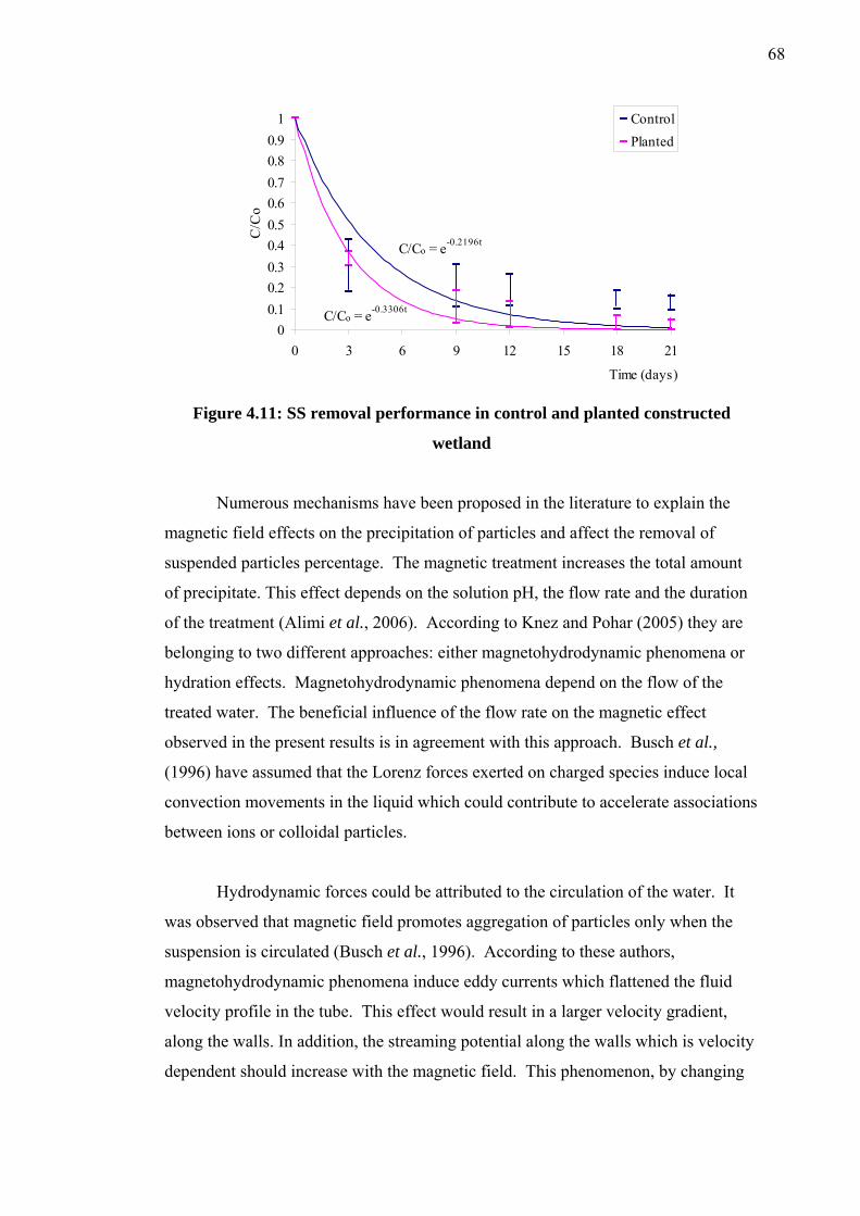
68
C/Co = e-0.3306t
C/Co = e-0.2196t
00.10.20.30.40.50.60.70.80.9
1
0 3 6 9 12 15 18 21
Time (days)
C/C
o
ControlPlanted
Figure 4.11: SS removal performance in control and planted constructed
wetland
Numerous mechanisms have been proposed in the literature to explain the
magnetic field effects on the precipitation of particles and affect the removal of
suspended particles percentage. The magnetic treatment increases the total amount
of precipitate. This effect depends on the solution pH, the flow rate and the duration
of the treatment (Alimi et al., 2006). According to Knez and Pohar (2005) they are
belonging to two different approaches: either magnetohydrodynamic phenomena or
hydration effects. Magnetohydrodynamic phenomena depend on the flow of the
treated water. The beneficial influence of the flow rate on the magnetic effect
observed in the present results is in agreement with this approach. Busch et al.,
(1996) have assumed that the Lorenz forces exerted on charged species induce local
convection movements in the liquid which could contribute to accelerate associations
between ions or colloidal particles.
Hydrodynamic forces could be attributed to the circulation of the water. It
was observed that magnetic field promotes aggregation of particles only when the
suspension is circulated (Busch et al., 1996). According to these authors,
magnetohydrodynamic phenomena induce eddy currents which flattened the fluid
velocity profile in the tube. This effect would result in a larger velocity gradient,
along the walls. In addition, the streaming potential along the walls which is velocity
dependent should increase with the magnetic field. This phenomenon, by changing
69
the surface charge, could throw out of balance the calcocarbonic equilibrium in the
vicinity of the tubing walls (Knez and Pohar, 2005).
Magnetohydrodinamic phenomena could also concern the electrical double
layer near the charged surface of particles. This interpretation seems receivable for
many experimental results of the literature where highly supersaturated waters were
treated by magnetic field (Barrett and Parsons, 1998). The aggregation of the
colloidal particles under the influence of electrostatic phenomena would contribute to
accelerate the crystal growth and the precipitation processes thus increase a SS
removal percentage.
According to Johan (2003), the SS removal achieved to 85.4% with magnetic
treatment effects. From the study, high strength of magnet to 0.55T increase the
precipitation and sedimentation of particles support mechanism based on Lorentz
forces to double electric and hydrate layer of the particles. The magnetic field could
changes charge density at particles surface. Interaction between particles, affects to
aggregation and coagulation, thus destabilized the suspended particles. When the
destabilized particles exposed to high strength magnetic field, the magnetic forced
will exist exceeding the shear force and produce larger particles thus increase the
removal rate.
4.5 Heavy Metals Uptake by plants
The plants were harvested in the end of both experiment periods. Heavy
metal analysis of plants roots and leaves for species, Limnocharis flava and
Eichhornia Crassipes, shows that both species is capable of accumulate heavy metals
like iron and manganese as demonstrated in Figure 4.12 and Figure 4.13 for both
plants. For Limnocharis flava 54% Fe uptake by leaves while 44% uptake by roots
and Mn uptake by roots was 51% while 34% by leaves. While for Eichhornia
crassipes (water hyacinth), heavy metals were found to have accumulated in roots
more than leaves.
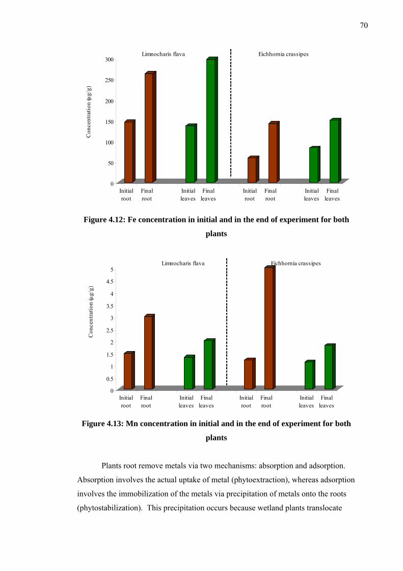
70
0
50
100
150
200
250
300
Con
cent
ratio
n (g
/g)
Initialroot
Finalroot
Initialleaves
Finalleaves
Initialroot
Finalroot
Initialleaves
Finalleaves
Limnocharis flava Eichhornia crassipes
Con
cent
ratio
n (µ
g/g)
Figure 4.12: Fe concentration in initial and in the end of experiment for both
plants
0
0.5
1
1.5
2
2.5
3
3.5
4
4.5
5
Con
cent
ratio
n (g
/g)
Initialroot
Finalroot
Initialleaves
Finalleaves
Initialroot
Finalroot
Initialleaves
Finalleaves
Limnocharis flava Eichhornia crassipes
Con
cent
ratio
n (µ
g/g)
Figure 4.13: Mn concentration in initial and in the end of experiment for both
plants
Plants root remove metals via two mechanisms: absorption and adsorption.
Absorption involves the actual uptake of metal (phytoextraction), whereas adsorption
involves the immobilization of the metals via precipitation of metals onto the roots
(phytostabilization). This precipitation occurs because wetland plants translocate
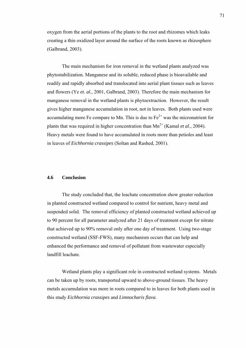
71
oxygen from the aerial portions of the plants to the root and rhizomes which leaks
creating a thin oxidized layer around the surface of the roots known as rhizosphere
(Galbrand, 2003).
The main mechanism for iron removal in the wetland plants analyzed was
phytostabilization. Manganese and its soluble, reduced phase is bioavailable and
readily and rapidly absorbed and translocated into aerial plant tissues such as leaves
and flowers (Ye et. al., 2001, Galbrand, 2003). Therefore the main mechanism for
manganese removal in the wetland plants is phytoextraction. However, the result
gives higher manganese accumulation in root, not in leaves. Both plants used were
accumulating more Fe compare to Mn. This is due to Fe2+ was the micronutrient for
plants that was required in higher concentration than Mn2+ (Kamal et al., 2004).
Heavy metals were found to have accumulated in roots more than petioles and least
in leaves of Eichhornia crassipes (Soltan and Rashed, 2001).
4.6 Conclusion
The study concluded that, the leachate concentration show greater reduction
in planted constructed wetland compared to control for nutrient, heavy metal and
suspended solid. The removal efficiency of planted constructed wetland achieved up
to 90 percent for all parameter analyzed after 21 days of treatment except for nitrate
that achieved up to 90% removal only after one day of treatment. Using two-stage
constructed wetland (SSF-FWS), many mechanism occurs that can help and
enhanced the performance and removal of pollutant from wastewater especially
landfill leachate.
Wetland plants play a significant role in constructed wetland systems. Metals
can be taken up by roots, transported upward to above-ground tissues. The heavy
metals accumulation was more in roots compared to in leaves for both plants used in
this study Eichhornia crassipes and Limnocharis flava.

72
Magnetic field effect also enhanced the removal of nutrient, heavy metal and
suspended solid. The magnetic treatment depends on design and operation of
magnetic treatment device. Some factors are magnetic strength, magnetic
orientation, flowrate and type of pipe used. pH also an important factor to getting an
optimum magnetic effect.

CHAPTER 5
CONCLUSION AND RECOMMENDATION
5.1 Conclusion
From the study of leachate treatment with subsurface flow and free water
surface flow (SSF-FWS) constructed wetland under influence of magnetic field, high
removal efficiency achieved for all parameter analysed. Treatment under influence
of magnetic field can enhance the performance of SSF-FWS constructed wetland.
Magnetic field can reduce time of treatment and very effective in removing the
pollutants in leachate especially suspended solids and heavy metal.
The result shows great removal efficiency with 98.7% NH3-N, 90.2% PO43-,
98.7% Fe, 92.5% Mn and 94.3% SS removal in planted system while in control
system shows removal of 93.53% of NH3-N, 87.4% of PO43-, 97.5% of Fe, 89.3% of
Mn and 89% of SS. The planted system was reduced the initial leachate
concentration for all parameter analyzed to exceed 90 percent removal. In this study,
Limnocharis flava and Eichhornia crassipes did attribute to suspended solid,
nutrients and heavy metals removal.
The usage of constructed wetlands to treat landfill leachate is a valuable and
appropriate technology nowadays. Wetland plants play an important role in wetland
systems. It provide surface for microbial to attach and growth, sufficient leachate
residence time, trapping and settlement of suspended leachate components. These
were results of resistance to hydraulic flow, surface area for pollutant adsorption,
74
uptake and storage in plant tissues, roots or leaves and diffusion of oxygen from
aerial parts to the rhizosphere. It was also responsible in reducing the heavy metals
in leachate. Gravel, sand and soil that were used as the media are also an effective
combination to remove pollutants.
At the end of study, the plants harvested and analyzed for heavy metals
uptake by plants roots and leaves. Limnocharis flava and Eichhornia crassipes had
shown capability to absorb heavy metals in leachate. Limnocharis flava ccumulate
Fe higher in leaves rather than roots whereas Mn accumulate higher in roots.
Eichhornia crassipes accumulates higher concentrations of heavy metals in root than
in leaves. This demonstrates that uptake was significant and root provides a surface
for particulate adsorption and microbial growth.
5.2 Recommendation for Future Work
For future work, it suggests to:
(i) Using different arrangement of constructed wetland with study the FWS-
SSF arrangement constructed wetland performance.
(ii) Further studies should vary the flow rates and detention time of constructed
wetland
(iii) Using another types of wetland plants such as common reed (Phragmites)
and cattail (Typha) for subsurface flow wetland.
(iv) Check the organics (BOD and COD) and pH removal
(v) Check nutrient uptake by plants, so the mechanism of nutrient removal can
be understand.

REFERENCES
Aeslina Abdul Kadir (2004). Landfill Leachate Treatment Performance in
Subsurface Flow Constructed Wetlands Using Safety Flow System, Universiti
Teknologi Malaysia: Master thesis
Ain Nihla Kamarudzaman (2006). Leachate Treatment using SSF-FWS Constructed
Wetland. Universiti Teknologi Malaysia: Master Thesis.
Al-Muzaini, S., Beg, M.U. and Muslmani, K. (1995). Characterization of Landfill
Leachates at a Waste Disposal Site in Kuwait. Environment Intemational. 21: 399
– 405.
Alimi, F., Tlili, M., Claude, G., Maurin, G., and Ben Amor, M. (2006). Effect of a
magnetic water treatment on homogeneous and heterogeneous precipitation of
calcium carbonate. Water Research. 40:1941 – 1950
APHA (2002). Standard Methods for the Examination of Water and Wastewater,
American Public Health Association, AWWA, and WPCF, Washington DC.
Ayaz, S.A. and Acka, L. (2001). Treatment of wastewater by natural systems.
Environment International.26: 189-195
Baker, J. S., and Judd, S.J. (1996). Magnetic amelioration of scale formation. Water
Research. 30(2): 247-260
Barlaz, M. A. (1996) Microbiology of solid waste landfills. In: Microbiology of Solid
Waste. A.C. Palmisano and M.A. Barlaz (eds). CRC Press. Boca Raton. Florida.
Barlaz, M. A. and Gabr, M. A. (2001). Closing the Gaps in the Regulation of
Municipal Solid Waste Landfills: Defining the End of the Post-Closure
Monitoring Period and Future Stability of Leachate Recirculation Landfills. In
Catherine C. Galbrand (2003). Naturalized Treatment Wetland for Contaminant
Removal: A Case Study of the Burnside Engineerd Wetland for Treatment of
Landfill Leachate. Dalhousie University Master Thesis, Halifax, Nova Scotia.
76
Barrett, R.A. and Parsons, S.A. (1998). The Influence of Magnetic Fields on Calcium
Carbonate Precipitation. Water Research. 32:609 – 612.
Belova, V. (1972). Magnetic Treatment of Water. Society Science Revolution
Scientist Development U.S.S.R. 3:150-156
Beruto, D.T., and Giordani, M. (1995) Effects of low frequency electromagnetic
fields on crystal growth from solution. In: Compton, R.G. and Hancock, G.(1995)
Research in Chemical Kinetics, Elsevier Science. Volume 3: pg 175
Bernardin, J.D. and Chan, S.H (1991). Magnetic effect on simulated brine properties
pertaining to magnetic water treatment. Journal of Crystal Growth. 108: 792
Bethan, P. (1996). Ammonium and Nitrate Removal from Belle Isle Landfill Leachate
in Constructed Wetland Cells. College of Environmental Science and Forestry,
New York: Master Thesis.
Bogatin, J., Bondarenko, N.P, Gak, E.Z, Rokhinson, E.E, and Ananyev, I.P. (1999).
Magnetic treatment of irrigation water: experimental results and application
conditions. Environmental Science. 33: 1280.
Bolto, B.A. (1990). Magnetic particle technology for wastewater treatment, Waste
Management. 10 (1): 11.
Bruns, S.A., Klassen, V.I. and Konshina, A.K. (1966). Change in the extinction of
light by water after treatment in magnetic field. Analytical Chemistry. 23: 214.
Brix, H. (1993). Wastewater Treatment in Constructed Wetlands: System Design,
Removal Processes and Treatment Performance. In: G.A. Moshiri
(ed).Constructed Wetlands for Water Quality Improvement. Lewis Publishers:
Boca Raton. p.9-22.
Brix, H., (1994). Functions of macrophytes in constructed wetlands. Water Science
Technology. 29: 71–78.
Brix, H., (1997). Do macrophytes play a role in constructed treatment wetlands?
Water Science Technology. 35:11–17.
Brown, D. S. and Reed, S. C. (1994). Inventory of constructed wetlands in the United
States. Water Science Technology. 29: 309-318.
Bruk, O.B., Klassen, V.I., and Krylov, O.T. (1987). Mechanism of Magnetic
Treatment of Disperse System. Soviet Surface Engineering Application and
Electrochemical (Electronmaya Obrabotca Materiolov). 6: 45-50.
Bulc, T.G. (2006). Long term performance of a constructed wetland for landfill
leachate treatment. Ecological Engineering. 26: 365–374.
77
Busch, K.W., Busch, M.A., McAtee, J.L., Darling, R.E., and Parker, D.H. (1985).
Evaluation of the Principles of Magnetic Water Treatment. API Report 960,
Report by American Petroleum Institute, Washington DC.
Busch, K. W., Busch, M.A., Parker, D.H., Darling, R.E., and McAtee Jr., J.L. (1986).
Studies of a water treatment device that uses magnetic fields. Corrosion. 42(4):
211-221.
Chiba, A., Kawazu, K., Nakanu, O., Tamura, T., Yoshihara, S. and Sato, E. (1994).
The Effects of Magnetic Fields on the Corrosion of Aluminium Foil in the
Sodium Chloride Solutions. Corrosion Science. 36 (3): 539-543.
Coey, J.M.D. and Cass, S. (2000). Magnetic Water Treatment. Journal of Magnetism
and Magnetic Materials. 209: 71 – 74.
Cameron, K., Madramootoo, C., Crolla, A. and Kinsley, C. (2003). Pollutant
Removal from Municipal Sewage Lagoon Effluents with a Free-Surface
Wetland. Water Research. 37: 2803–2812.
Chen, T.Y., Kao, C.M., Yeh, T.Y., Chien, H.Y. and Chao, A.C. (2006). Application
of a Constructed Wetland for Industrial Wastewater Treatment: A Pilot-scale
Study. Chemosphere. In press.
Cooper, P.F., Job, G.D., Green, M.B., and Shutes, R.B.E., 1996. Reed Beds and
Constructed Wetlands for Wastewater Treatment. WRc Publications,
Medmenham, Marlow, UK.
Cossu, R., Haarstad, K., Lavagnolo, M.C. and Littaru, P. (2001). Removal of
municipal solid waste COD and NH4-N by phyto-reduction: A laboratory-scale
comparison of terrestrial and aquatic species at different organic loads.
Chemosphere. 16: 459-470.
Christensen, T. H., Cossu, R. and Stegmann, R. (1992). Landfilling of Waste
Leachates. Elseveir Science Publishers LTD. 70-71.
Crolla, A (2004) Constructed Wetland In Canada, ATAU Course Notes. Collège
d’Alfred – University of Guelph.
Cronk, J.K. and Fennessy, M.S. (2001). Wetland Plants : Biology and Ecology.
Lewis Publishers, United States of America.
DeBusk, T.A., Burgoon, P.S., and Reddy, K.R., (1989). Performance of a pilot scale
water hyacinth-based secondary treatment system. Journal Water Pollution
Control Federation. 61: 1217–1224.
78
Donaldson, J. D., (1988). HDL Symposia at the Universities of York and Aston,
January 1988, New Scientist, 117
Donaldson, J.D. (1990). Magnetic Treatment of Fluids. Brewer’s Guardian. July 20-
24.
Duffy, E.A. (1977). Investigation of Magnetic Water Treatment Devices. Clemson
University, Clemson, S.C. Thesis PhD.
Duffy, E.A. (1997). Investigation of Magnetic Water Treatment Devices. Clemson
University, Clemson, S.C.: Thesis PhD.
Eckhardt, David A.V., Surface, J.M. and Peverly J.H. (1998). A constructed wetland
system for leachate treatment of Landfill Leachate, Monroe Country, New York.
In: Constructed Wetland for the treatment of landfill leachate, G. Mulamootil, E.
A. McBean and F. Rovers, eds., CRC Press, Boca Raton, Florida, 205-222.
El-Fadel, M., Findikakis, A.N. and Leckie, J.O.(1997). Environmental impacts of
solid waste landfilling, Journal of Environmental Management. 50: 1–25.
El-Fadil, M, E., Bou-Zeid, W., Chahine, B., and Alayli (2002). Temporal variation of
leachate quality from pre-sorted and baled municipal solid waste with high
organic and moisture content. Journal of Waste Management. 22: 269–282.
Ellingsen F.T dan Kristiansen. H. (1979). Does magnetic treatment influence
precipation of calcium carbonate from supersaturated solutions.
Bioeletromagnetic. 6: 169 – 175
Emberton, J.R. (1986). The biological and chemical characterization of landfills. In:
Emberton JR, Emberton RF, editors. Energy from landfill gas, p. 150–63.
Fadil, O., Johan, S., and Zulfa, F. (2004). Sedimentation of suspended solid under
influence of magnetic field, 2nd Bangi World Conference on Environmental
Management, Sept 13 – 14, UKM & EMS Malaysia, 35 – 40
Faseur, A. Dooren, Juan, Vanbrabant, R. and Goossens, W.R.A. (1988).
Electromegnetic Treatment of Wastewater. Filtration and Separation. 25(5):
344-347.
Florenstano, E.J., Marchello, J.M. and Bhat, S.M. (1996). Magnetic Water Treatment
in Lieu of Chemicals. Chemical Engineering World. 31(10): 133-136
Gamayunov, N. I. (1983). Coagulation of Suspension After Magnetic Treatment.
Journal of Applied Chemistry of the USSR (Zhurnal Prikladnoi Khimii). 56(5):
975-982.
79
Gruber, C.E. and Carda, D.D. (1981). Performance Analysis of Permanent Magnet
Type Water Treatment Devices. Research and Education in Water Quality
Report. South Dakato Scholl of Mines and Technology, Rapid City, South
Dakato, USA.
Gearheart, R. A. (2006) Constructed Wetland for Natural Wastewater, Southwest
Hydrology, Humboldt State University
Gersberg, R.M., Elkins, B.V., and Goldman, C.R., 1983. Nitrogen removal in
artificial wetlands. Water Resources. 17: 1009–1014.
Gonet, B. (1985). Influence of Constant Magnetic Fields on Certain Physicochemical
Properties of Water. Bioelectromagnetics. 6: 169 – 175.
Greenway, M., (1997). Nutrient content of wetland plants in constructed wetlands
receiving municipal effluent in tropical Australia. Water Science Technology. 35:
135–142.
Greenway, M. and Woolley, A. (1999). Constructed Wetlands in Queensland:
Performance Efficiency and Nutrient Bioaccumulation. Ecological Engineering.
12: 39 – 55.
Halvadakis, C. P. (1983). Methanogenesis in solid-waste landfill bioreactors. PhD
Dissertation, Stanford University, Stanford CA.
Hammer, D.A., (1989). Constructed wetlands for wastewater treatment. Municipal,
industrial and agricultural. In: Proceedings from the First International
Conference on Constructed Wetlands for Wastewater Treatment, held in
Chattanooga, TN, June 13–17. Lewis, Chelsea, MI.
Hammer, D.A., Knight, R.L., (1994). Designing constructed wetlands for nitrogen
removal. Water Science Technology. 29: 15–27.
Hasson, D. and Bramson, D. (1981). The Performance of a Magnetic Water
Conditioner Under Accelerated Scaling Conditions. Proceedings of Progress in
the Prevention of Fouling of Industrial Plant, 217 – 223. April 1981,
Nottingham, UK. Institute of Corrosion Science and Technology.
Herzorg, R.E., Shi, Q.H., Patil, J.N. and Katz, J.L. (1989). Magnetic Water
Treatment: The Effect of Iron on Calcium Carbonate Nucleation and Growth.
Langmuir. 5(3): 861-866.
Higashitani, K., Okuhara, K. and Hatade S. (1992). Effects of Magnetic Fields on
Stability of Nonmagnetic Ultrafine Colloidal Particles. Journal of colloid and
interface science. 152: 125 – 131.
80
Higashitani K., Kage A., Katamura S., Imai K. and Hatade S. (1993). Effects of a
Magnetic Field on the Formation of CaCO3 Particles. Journal of colloid and
interface science. 1: 90 – 95.
Higashitani, K., Iseri, H., Okuhara, K., Kage, A. and Hatade, S. (1995). Magnetic
Effects on Zeta Potential and Diffusivity of Nonmagnetic Colloidal Particles.
Journal of Colloid and Interface Science. 172(1): 383-388.
Hirschbein, B.L. Brown, D.W. and Whitesides, G.M. (1982). Magnetic Separations
in Chemistry and Biochemistry. Chemtech Magazine Mac 1982.
Holysz, L., Chibowski, E. and Szczes, A. (2003). Influence of Impurity Ions and
Magnetic Field on the Properties of Freshly Precipitated Calcium Carbonate.
Water Research, In press.
Huett, D.O., Morris, S.G., Smith, G. and Hunt, N. (2005). Nitrogen and Phosphorus
Removal from Plant Nursery Runoff in Vegetated and Unvegetated Subsurface
Flow Wetlands. Water Research. 39: 3259–3272.
Ifill, A.S., Baker, J.S., and Judd, S.J. (1996). Magnetically-Enhanced Chemical
Disinfection. Transaction of the Institution of Chemical Engineering (Part B).
74(2): 120-124.
Ingersoll, T.L. and Baker, L.A. (1998) Nitrate Removal in wetland microcosms.
Water Resource. 32: 677-684.
IWA (2000). Constructed wetlands for Pollution Control. Processes, Performance,
Design and Operation. International Water Association Publishing, London.
Jenkins, R. L. and Pettus, J.A.(1985) The use of in-vitro anaerobic landfill samples
for estimating gas generation rates. In: Biotechnology advances in processing
municipal wastes for fuels and chemicals, Antonopoulos, A.A. (ed.), (Argonne
National Laboratory Report ANL/CNVS-TM-167), 419.
Johan Sohaili (2003). Kesan Medan Magnet Terhadap Pengenapan Zarah Terampai
Dalam Kumbahan. Univesiti Teknologi Malaysia: PhD thesis.
Johan, S., Fadil, O., and Zularisam, A.W., (2004). Effect of magnetic fields on
suspended particles in sewage, Malaysian Journal of Science. 23: 141 – 148
Johnson, K.D., Martin, C.D., Moshiri, G.A. and McCrory, W.C. (1999). Performance
of a Constructed Wetlands Leachate Treatment System at the Chunchula
Landfill, Mobile County, Alabama, In : edited by Mulamoottil, G., McBean, E.A.
and Rovers, F. Constructed Wetlands for the Treatment of Landfill Leachates.
Lewis Publishers, United States of America.
81
Jung, J., Sanji, B., Godbole, S., and Sofer, S. (1993). Biodegradation of phenol. A
comparative study with and without applying magnetic fields. Journal of
Chemical Technology Biotechnology. 556: 73– 6.
Kadlec, R. H. (1999). Constructed Wetlands for treating landfill leachate. Lewis
Publishers, Boca Raton, FL. 17-31.
Kadlec, R.H (2000). The inadequacy of first-order treatment wetland models.
Ecological Engineering. 15: 105–119
Kadlec, R. H and Knight, R.L. (1996). Treatment Wetlands. CRC Press LCC: Boca
Raton, Florida.
Kamal, M., Ghaly, A.E., Mahmoud, N. and Côté, R. (2004). Phytoaccumulation of
Heavy Metals by Aquatic Plants. Environmantal International. 29: 1029 – 1039.
Kappelmeyer, U. (2005) Landfill Leachate Treatment in Constructed Wetlands:
Removal of High Nitrogen Loads, Eng. M.Sc. Diego Paredes.
Klapper, H. (1992). Eutrophication. G. Fischer Verlag Jena.
Klassen, V. I., (1981). Develop Miner. Proces. Part B Miner. Proces: 1077–1097
Knez, S. and Pohar, C., (2005). The magnetic field influence on the polymorph
composition of CaCO3 precipitation from carbonized aqueous solutions. Journal
Colloid Interface Science. 281: 377–388.
Knight, R. L. (1997). Wildlife habitat and public use benefits of treatment wetlands.
Water Science Technology. 35 (5): 35-43.
Kurniawan, T.A., Lo, W.H. and Chan, G.Y.S. (2006). Physico-chemical treatments
for removal of recalcitrant contaminants from landfill leachate. Journal of
Hazardous Materials. B129: 80–100.
Lee, Y. F. (2004). Rainfall effects to the performance of SSF constructed wetlands in
leachate treatment. Universiti Teknologi Malaysia: Master Thesis
Lee, G.F. and Lee, J. (2001). Assessing the Water Quality Impacts of Phosphorus in
Runoff from Agricultural Land. Proceedings of American Chemical Society Agro
Division Symposium: Environmental Impacts of Fertilizer Products in Soil, Air
and Water. American Chemical Society. Chicago.
Liburkin, V.G., Kondrater, B.S. and Pavlyukova, T.S. (1986). Action of Magnetic
Treatment of Water on the Structure Formation of Gypsum. Glass and Ceramics
(Steklo I Keramika). 43 (3-4): 116-119.
82
Liehr, S., Kozub, D., Rash, J., Sloop, M., Doll, B., Rubin, R., House, H., Haws, S.
and Burks, D. (2000) Constructed Wetlands Treatment of High Nitrogen Landfill
Leachate. Water Environment Research Foundation: Alexandria, Virginia.
Lim, W.H., Tay, T.H. and Kho, B.L. (2002). Plants Used in the Putrajaya Wetland
System and Problems Associated with Their Establishment and Maintenance. In :
Editors : Mansor, M., Eng, L.P. and Shutes, R.B.E. Constructed Wetlands :
Design, Management and Education. Universiti Sains Malaysia Publisher,
Malaysia.
Lim, W. H., Kho, B. L., Tay, T. H., and Low, W. L. (1998). Plants of Putrajaya
Wetlands. Selangor: Putrajaya Holdings Sdn. Bhd. Putrajaya.
Lin, Y.F., Jing, S.R., Lee, D.Y., Wang, T.W. (2002) Nutrient removal from polluted
aquaculture wastewater using constructed wetlands system. Aquaculture. 209:
169–184.
Lin, Y.F., Jing, S.R., Lee, D.Y., Chang, Y.F., Chen, Y.M., and Shih, K.C. (2005)
Performance of a constructed wetland treating intensive shrimp aquaculture
wastewater under high hydraulic loading rate, Environmental Pollution. 134:
411-421
Lipus, L.C., Krope, J. and Crepinsek, L. (2001). Dispersion Destabilization in
Magnetic Water Treatment. Journal of Colloid and Interface Science. 236: 60-66
Liu, J., Qiu, C., Xiao, B., Cheng, Z., (2000). The role of plants in channel-dyke and
field irrigation systems for domestic wastewater treatment in an integrated eco-
engineering system. Ecological Engineering. 16: 235-241.
Maine, M.A., Sun˜ e, N., Hadad, H., Sa´nchez, G., Bonetto, C., (2005). Phosphate
and metal retention in a small-scale constructed wetland for waste-water
treatment. In: Golterman, H.L., Serrano, L. (Eds.), Phosphate in Sediments.
Backhuys Publishers, Leiden, pp. 21–31.
Mantovi, P., Marmiroli, M., Maestri, E., Tagliavini, S., Piccinini, S. and Marmiroli,
N. (2003). Application of a Horizontal Subsurface Flow Constructed Wetland on
Treatment of Dairy Parlor Wastewater. Bioresource Technology. 88: 85 – 94.
Martin, J., Hofherr, E., Quigley, M.F., (2003). Effects of Typha latifolia transpiration
and harvesting on nitrate concentrations in surface water of wetland microcosms.
Wetland 23 (4): 835-844
83
Masbough, A., Frankowski, K., Hall, K.J. and Duff, S.J.B. (2005). The Effectiveness
of Constructed Wetland for Treatment of Woodwaste Leachate. Ecological
Engineering. 25: 552 – 566.
Maschinski, J., Southam, G., Hines, J., Strohmeyer, S., (1999). Efficiency of a
subsurface constructed wetland system using native southwestern US plants.
Journal of Environmental Quality. 28 (1): 1665–1673.
Mashhor, M., Sofiman, O. and Asyraf, M. (2002). Management of Wetland Weeds in
Aquatic Systems. In : Editors : Mansor, M., Eng, L.P. and Shutes, R.B.E.
Constructed Wetlands : Design, Management and Education. Universiti Sains
Malaysia Publisher, Malaysia.
Mason, C. H. (1998). Biology of freshwater pollution Third Edition. Addison Wesley
Longman Limited. England.
McBean, E. A., Rovers, F. A. and Farquhar, G. J. (1995). Solid Waste Landfill
Leachate Desalination. 103.
McBean, E. and Rovers, F. (1999) Landfill Leachate Characteristics as input for the
design of wetlands used as treatment system. In: Mulamoottil, G., McBean, E.A.
and Rovers, F., (1999) Constructed Wetlands for the Treatment of Landfill
Leachates, Lewis Publisher, Boca Raton, Florida
Mitsch, W.J. and Gosselink, J.G. (1986). Wetlands. New York, Van Nostrand
Reinhold Company Inc.
Mulamoottil, G., McBean, E.A. and Rovers, F., (1999). Constructed Wetlands for the
Treatment of Landfill Leachates, Lewis Publisher, Boca Raton, Florida
Muna Muhammad (2003). Pengolahan Air Larut Lesap Melalui Tanah Bencah
Buatan Aliran Sub-Permukaan Dengan Scirpus Globulosus Dan Ericaulon
Sexangulare Bagi Penyingkiran Logam Berat. Universiti Teknologi Malaysia:
Master Thesis.
Navratil, J.D. (2002). Adsorption and Nanoscale Magnetic Separation of Heavy
Metals from Water. Environmental Protection Act (EPA).
Navratil, J.D. (2003). Potential of Magnetic Adsorption/Filtration for
Hydrometallurgical Wastewater Treatment. Fifth International Conference in
Honor of Professor Ian Ritchie –Volume 1: Leaching and Solution Purification.
Edited by Young, C.A., Alfantazi, A.M., C.G. Anderson, Dreisinger, D.B.,
Harris, B.and James, A. TMS (The Minerals, Metals & Materials Society)
84
Nazaitul Shila Rasit (2006). Landfill Leachate Treatment Using Subsurface Flow
Constructed Wetland Enhanced With Magnetic Field. Universiti Teknologi
Malaysia: Master Thesis.
Nelson,E. A. Specht, W.L. and Knox, A.S. (2004) Metal Removal From process and
stormwater discharges by constructed treatment wetland WSRC-MS-2004-
00763, Department of Energy, Office of Scientific and Technical Information,
US.
Noor Ida Amalina Ahamad Nordin (2006) Leachate Treatment Using Constructed
Wetland With Magnetic Field. Universiti Teknologi Malaysia: Master Thesis.
Oshitani, J., Yamada, D., Miyahara, M and., Higashitani, K., (1999) Magnetic effects
on Ion Exchange Kinetics. Journal Colloid Interface Science. 210: 1-7
Ozeki, S., Wakai, C. and Ono, S. (1991). Is a Magnetic Effect on Water Adsorption
Possible?. Journal of Physical Chemistry. 95(26): 10557-10559.
Pant, H.K., Reddy, K.R., Lemon, E., (2001). Phosphorus retention capacity of root
bed media of sub-surface flow constructed wetlands. Ecological Engineering. 17:
345–355.
Parson, S.A. (2000). Advances in Magnetic Treatment Research. Proceedings of the
3rd International Symposium on New Magneto-Science. Tokyo, Japan.
Parsons, S., Judd, S.J., Stephenson, T., Udol, S., Wang, B.L., (1997) Magnetically
augmented water treatment. Transaction of the Institution of Chemical
Engineering 75(B): 98–104.
Partidas, H (1995). Magnetic Fluid Conditioning Tools: Removal and Inhibition of
Production Reports. Petromin Nov. 66-72.
Pempkowiak, H.O. and Klimkowska, K. (1999). Distribution of Nutrients and Heavy
Metals in a Constructed Wetland System. Chemosphere, Elsevier Science Ltd.
39: 303 – 312.
Qasim, S. R., and Chiang, W. (1994). Sanitary landfill leachate: generation, control,
and treatment. Technomic Publishing, Lancaster.
Rash, J. K. and Liehr, S. K. (1999). Flow pattern analysis of constructed wetlands
treating landfill leachate. Water Science Technology. 40(3): 309-315.
Reed, S.C., Crites, R.W., and Middlebrooks, E.J. (1995). Natural Systems for Waste
Management and Treatment, McGraw-Hill, New York, 433 pp.
85
Reddy, K. R., Kadlec, R. H., Flaig, E. and Gale, P. M. (1999). Phosphorus retention
in streams and wetlands: a review. Critical Review Environmental Science
Technology. 29: 83-146.
Reddy, K.R., Sutton, D.L., and Bowes, G., (1983). Freshwater aquatic plant biomass
production in Florida. Soil Crop Science Soc. Fla. Process. 42: 28–40.
Reddy, K.R., and Debusk, W.F. (1985) Nutrient Removal potential of selected
aquatic macrophytes. Journal of Environmental Quality. 14: 459-462
Reddy, K.R., and D’Angelo, E.M., (1990). Biomass yield and nutrient removal by
water hyacinth (Eichhornia Crassipes) as influenced by harvesting frequency.
Biomass. 21: 27–42.
Reddy, K.R., and Smith, W.H. (Eds.). (1987). Aquatic Plants for Water Treatment
and Resource Recovery. Magnolia Publishing, Orlando, FL, USA.
Reinhart, D.R. (1995). Why wet landfills with leachate recirculation are effective. In:
Dunn JR, Singh UP, editors. Landfill closures: environmental protection and
land recovery. San Diego, CA: Geotechnical Special Publication. 53: 93–99.
Reinhart, D.R. (1996). Full-scale experiences with leachate recirculating landfill:
case studies. Waste Management Research. 14: 347–365.
Reinhart, D.R. and Al-Yousfi, B. (1996). The impact of leachate recirculation on
municipal solid waste landfill operating characteristics. Waste Management and
Research. 14: 337-346.
Richards, M. (1992). Constructed Wetlands to Ameliorate Metal-rich Mine Waters.
Review of Existing Literature. R&D, National Rivers Authority, Bristol, UK. 1:
102.
Sawaittayothin, V. and Polprasert, C. (2006). Nitrogen mass balance and microbial
analysis of constructed wetlands treating municipal landfill leachate. Bioresource
Technology, In Press.
Schwartz, M.F., and Boyd, C.E., (1995). Constructed wetlands for treatment of
channel catfish pond effluents. Program Fish-Culture. 57: 255– 267.
Shaikh, A. M. N. and Dixit, S.G. (1992). Removal of phosphate from waters by
Precipitation and High Gradient Magnetic Separation. Water Research. 26(6):
845-852.
Sheoran, A.S. and Sheoran, V. (2006). Heavy Metal Removal Mechanism of Acid
Mine Drainage in Wetlands: A Critical Review. Minerals Engineering. 19: 105–
116.
86
Shepard, D.P. Edling, B. and Reimers, R. (1995). Magnetic Water Treatment. Golf
Course Management. 63(3): 55-58.
Shutes, R.B.E., Revitt, M., Forshaw, M. and Winter, B. (2002). Constructed Wetland
Monitoring and Management for Urban Runoff Management. In : Editors :
Mansor, M., Eng, L.P. and Shutes, R.B.E. Constructed Wetlands : Design,
Management and Education. Universiti Sains Malaysia Publisher, Malaysia.
Silva, A.C., Dezotti, M., and Sant’Anna, G.L. (2003). Treatment and detoxication of
a sanitary landfill leachate. Chemosphere. 55: 207–214.
Soltan, M.E. and Rashed, M.N. (2003). Laboratory study on the survival of water
hyacinth under several conditions of heavy metal concentrations. Advances in
Environmental Research. 7:321–334
Spiegel, M.S. (1998). Method and Apparatus for Applying Magnetic Fields to Fluids.
(US Patent No. 035826).
Srebrenik, S., Nadiv, S. and Lin, I.J. (1993). Magnetic Treatment of Water- A
theoretical Quantum Model Magnetic and Electrical Separation. 5(2): 71-91.
Stefan, E.B., Eriksson, P.G., Graneli, W., Leonardson, L. (1994) Influence of
macrophytes on nitrate removal in wetlands. Ambio. 23: 363-366
Stowel, R., Ludwig, R., Colt, J., and Tchobanouglous, G. (1981). Concept in Aquatic
Treatment Systems Design. Journal Environmental Engineering Division. ASCE
vol. 107. No EE : 919.
Surface, J.M., Peverly, J.H., Steenhuis, T.S., and Sanford, W.E. (1993). Constructed
wetlands for landfill leachate treatment. In: Moshiri, G.A. (Ed.), Constructed
Wetlands for Water Quality Improvement. Lewis Publishers, Chelsea, MI, pp.
461-472.
Tanner, C. C. (1996). Plants for constructed wetland treatment systems. A
comparison of the growth and nutrient uptake of eight emergent. Ecological
Engineering.7: 59-83.
Tatsi, A.A. and Zouboulis, A.I. (2002). A field investigation of the quantity and
quality of leachate from a municipal solid waste landfill in a Mediterranean
climate (Thesaloniki, Greece). Advanced Environmental Resources. 6: 207–219.
Tchobanoglous, G., Theisen, H., and Vigil, S.A., (1993). Integrated Solid Waste
Management. McGraw-Hill. Inc., Singapore, pp. 418–419.
87
Terashima, Y., Ozaki, H., Sekine, M. (1986). Removal of Dissolved Heavy Metals
by Chemical Coagulation, Magnetic Seeding and High Gradient Magnetic
Filtration. Water Research. 20(5): 537-545.
Thien, S.H. (2005). Leachate Treatment by Floating Plants in Constructed Wetland.
Master Thesis, Universiti Teknologi Malaysia.
Thullen, J.S., Santoris, J.J., Mark Nelson, S. (2005). Managing vegetation in surface
flow wastewater treatment wetlands for optimal treatment performance.
Ecological Engineering. In Press.
Tsouris, C. and Scott, T.C. (1994). Flocculation of paramagnetic in a Magnetic Field.
Journal of Colloidal and Interface. 171: 319-330
Van Velsen, A.F.M. van der vos, G. Boersma, R. and de Reuver, J.L. (1990). High
Gradient Magnetic Separation Technique for Wastewater Treatment. Water
Science and Technology. 24(10): 195-203.
Vickl, W.S. (1991). Magnetic Fluid Conditioning. Proceedings of the 1991 Speciality
Conference on Environmental. American Society Chemical Engineering, New
York, July 8 – 10, Reno, NY, USA.
Vymazal, J., Brix, H., Cooper, P.F., Green, M.B., and Haberl, R. (1998). Constructed
Wetlands for Wastewater Treatment in Europe. Backhuys Publishers, Leiden,
The Netherlands.
Vymazal, J. (2005). Horizontal sub-surface flow and hybrid constructed wetlands
systems for wastewater treatment, Ecological Engineering. 25: 478–490
Vymazal, J. and Kropfelova, L. (2005). Growth of Phragmites Australis and
Phalaris Arundinacea in Constructed Wetlands for Wastewater Treatment in the
Czech Republic. Ecological Engineering. 25: 606 – 621.
Wan Salida Wan Mansor (2006). Effect of Magnetic Fields on Heavy Metals and
Nutrient Removal In Leachate.. Universiti Teknologi Malaysia: Master Thesis
Watson, J.T., Reed, S.C., Kadlec, R.H., Knight, R.L. and Whitehouse, A.E. (1989).
Performance expectations and loading rates for constructed wetlands. In:
Hammer, D.A. ed. Constructed wetlands for wastewater treatment: municipal,
industrial and agricultural. Chelsea, MI, USA: Lewis Publishers. 319-351.
Wetzel, R.G. (2000). Fundamental processes within natural and constructed wetland
ecosystems: short-tem vs. long-term objectives. In: Seventh Conference on
Wetland Systems for Water Pollution Control Proceedings, vol. 1, Lake Buena
Vista, Florida, November 11-16, pp 3-11

88
Yang, L., Chang, H.T, and Huang, M.L. (2001). Nutrient removal in gravel- and soil-
based wetland microcosms with and without vegetation. Ecological Engineering.
18: 91–105
Yang, B., Lan, C.Y., Yang, C.S., Liao, W.B., Chang, H. and Shu, W.S. (2006).
Long-Term Efficiency and Stability of Wetlands for Treating Wastewater of a
Lead/Zinc Mine and the Concurrent Ecosystem Development. Environmental
Pollution. In Press.
Yavuz, H. and Celebi, S.S. (2000). Effects of magnetic field on activity of activated
sludge in wastewater. Enzyme and Microbial Technology. 26: 22-27
Ye, Z.H., Whiting, S.N., Qian, J.H., Lytle, C.M., Lin, Z.Q., and Terry, N., (2001).
Trace element removal from coal ash leachate by a 10-year-old constructed
wetland. Journal of Environmental Quality. 30: 1710–1719.
Ying, T.Y., Yiacoumi, S. and Tsouris, C. (1999). High Gradient Magnetically
Seeded Filtration. Chemical Engineering Science. 55: 1101 – 1113.
Zulfa Fauzia, Fadil, O., Johan S., M. Faiqun A. (2005). Reduction of Organic
Concentration Under Magnetic Fields Up To 5500 Gauss. Proceeding in Seminar
Kebangsaan Pengurusan Persekitaran 2005, Universiti Kebangsaan Malaysia,
Bangi, 4 – 5 Julai.

APPENDIX
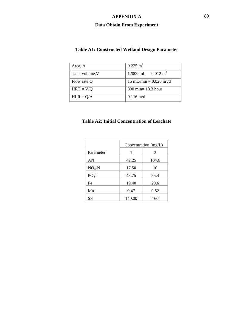
APPENDIX A 89
Data Obtain From Experiment
Table A1: Constructed Wetland Design Parameter
Area, A 0.225 m2
Tank volume,V 12000 mL = 0.012 m3
Flow rate,Q 15 mL/min = 0.026 m3/d
HRT = V/Q 800 min= 13.3 hour
HLR = Q/A 0.116 m/d
Table A2: Initial Concentration of Leachate
Concentration (mg/L)
Parameter 1 2
AN 42.25 104.6
NO3-N 17.50 10
PO4-3 43.75 55.4
Fe 19.40 20.6
Mn 0.47 0.52
SS 140.00 160
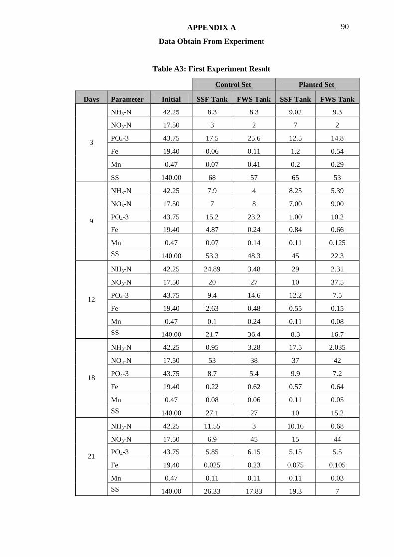
APPENDIX A 90
Data Obtain From Experiment
Table A3: First Experiment Result
Control Set Planted Set
Days Parameter Initial SSF Tank FWS Tank SSF Tank FWS Tank
NH3-N 42.25 8.3 8.3 9.02 9.3
NO3-N 17.50 3 2 7 2
PO4-3 43.75 17.5 25.6 12.5 14.8
Fe 19.40 0.06 0.11 1.2 0.54
Mn 0.47 0.07 0.41 0.2 0.29
3
SS 140.00 68 57 65 53
NH3-N 42.25 7.9 4 8.25 5.39
NO3-N 17.50 7 8 7.00 9.00
PO4-3 43.75 15.2 23.2 1.00 10.2
Fe 19.40 4.87 0.24 0.84 0.66
Mn 0.47 0.07 0.14 0.11 0.125
9
SS 140.00 53.3 48.3 45 22.3
NH3-N 42.25 24.89 3.48 29 2.31
NO3-N 17.50 20 27 10 37.5
PO4-3 43.75 9.4 14.6 12.2 7.5
Fe 19.40 2.63 0.48 0.55 0.15
Mn 0.47 0.1 0.24 0.11 0.08
12
SS 140.00 21.7 36.4 8.3 16.7
NH3-N 42.25 0.95 3.28 17.5 2.035
NO3-N 17.50 53 38 37 42
PO4-3 43.75 8.7 5.4 9.9 7.2
Fe 19.40 0.22 0.62 0.57 0.64
Mn 0.47 0.08 0.06 0.11 0.05
18
SS 140.00 27.1 27 10 15.2
NH3-N 42.25 11.55 3 10.16 0.68
NO3-N 17.50 6.9 45 15 44
PO4-3 43.75 5.85 6.15 5.15 5.5
Fe 19.40 0.025 0.23 0.075 0.105
Mn 0.47 0.11 0.11 0.11 0.03
21
SS 140.00 26.33 17.83 19.3 7

APPENDIX A 91
Data Obtain From Experiment
Table A4: Second Experiment Results
Control Set Planted Set
Days Parameter Initial SSF Tank FWS Tank SSF Tank FWS Tank
NH3-N 104.6 73.75 50.25 71.65 56.45
NO3-N 10 8 9 8 9
PO4-3 55.4 26 13 18.5 13
Fe 17.2 14.74 12.29 12.29 8.6
Mn 0.52 0.3 0.2 0.2 0.15
3
SS 160 35 29 8 45
NH3-N 104.6 34 21 26.2 15.9
NO3-N 10 7 10 15 9
PO4-3 55.4 2.9 10.3 7.5 8.8
Fe 17.2 7.37 4.67 4.32 5.65
Mn 0.52 0.09 0.08 0.11 0.08
9
SS 160 11 17 2 13
NH3-N 104.6 38.5 21.1 30.8 12.85
NO3-N 10 14 8 7 6
PO4-3 55.4 11.8 10.6 12.7 10.5
Fe 17.2 3.93 4.18 3.93 3.19
Mn 0.52 0.12 0.07 0.11 0.05
12
SS 160 13.8 18.1 19 10.4
NH3-N 104.6 32.1 18.25 34.95 11.1
NO3-N 10 12 16 6 13
PO4-3 55.4 7.4 8.4 6.9 4.7
Fe 17.2 1.47 1.47 1.56 1.43
Mn 0.52 0.8 0.051 0.095 0.044
18
SS 160 4.1 16 13 11.5
NH3-N 104.6 10.6 6.1 2.8 0.95
NO3-N 10 4.1 27 7.6 26
PO4-3 55.4 8.82 6.18 4.32 3.9
Fe 17.2 0.76 0.66 0.39 0.29
Mn 0.52 0.078 0.044 0.049 0.045
21
SS 160 13 28 10 10.4

APPENDIX A 92
Data Obtain From Experiment
Table A5: Heavy Metal Uptake by Limnocharis flava
Heavy Metal Uptake (µg/µg)
Exp 1 Exp 2 Plants component
Fe Mn Fe Mn
Initial 145 1.48 1344 1.83 Root
Final 262.5 3.00 1440 6.00
Initial 136 1.32 296 1.42
Final 296.4 2.00 1370 4.20
Leaves
Table A6: Heavy Metal Uptake by Eichhornia crassipes
Heavy Metal uptake (µg/µg)
Exp 1 Exp 2 Plants component
Fe Mn Fe Mn
Initial 58.64 1.2 20.9 0.27 Root
Final 141.4 5 59.84 3.00
Initial 82.6 1.124 1.2 1.14 Leaves
Final 149.8 1.8 5.7 1.40
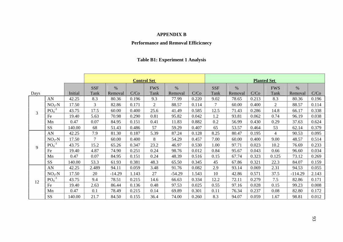
APPENDIX B
Performance and Removal Efficicnecy
Table B1: Experiment 1 Analysis
Control Set Planted Set
Days Initial SSF Tank
% Removal C/Co
FWS Tank
% Removal C/Co
SSF Tank
% Removal C/Co
FWS Tank
% Removal C/Co
AN 42.25 8.3 80.36 0.196 9.3 77.99 0.220 9.02 78.65 0.213 8.3 80.36 0.196 NO3-N 17.50 3 82.86 0.171 2 88.57 0.114 7 60.00 0.400 2 88.57 0.114 PO4
-3 43.75 17.5 60.00 0.400 25.6 41.49 0.585 12.5 71.43 0.286 14.8 66.17 0.338 Fe 19.40 5.63 70.98 0.290 0.81 95.82 0.042 1.2 93.81 0.062 0.74 96.19 0.038 Mn 0.47 0.07 84.95 0.151 0.41 11.83 0.882 0.2 56.99 0.430 0.29 37.63 0.624
3
SS 140.00 68 51.43 0.486 57 59.29 0.407 65 53.57 0.464 53 62.14 0.379 AN 42.25 7.9 81.30 0.187 5.39 87.24 0.128 8.25 80.47 0.195 4 90.53 0.095 NO3-N 17.50 7 60.00 0.400 8 54.29 0.457 7.00 60.00 0.400 9.00 48.57 0.514 PO4
-3 43.75 15.2 65.26 0.347 23.2 46.97 0.530 1.00 97.71 0.023 10.2 76.69 0.233 Fe 19.40 4.87 74.90 0.251 0.24 98.76 0.012 0.84 95.67 0.043 0.66 96.60 0.034 Mn 0.47 0.07 84.95 0.151 0.24 48.39 0.516 0.15 67.74 0.323 0.125 73.12 0.269
9
SS 140.00 53.3 61.93 0.381 48.3 65.50 0.345 45 67.86 0.321 22.3 84.07 0.159 AN 42.25 2.489 94.11 0.059 3.48 91.76 0.082 2.9 93.14 0.069 2.31 94.53 0.055 NO3-N 17.50 20 -14.29 1.143 27 -54.29 1.543 10 42.86 0.571 37.5 -114.29 2.143 PO4
-3 43.75 9.4 78.51 0.215 14.6 66.63 0.334 12.2 72.11 0.279 7.5 82.86 0.171 Fe 19.40 2.63 86.44 0.136 0.48 97.53 0.025 0.55 97.16 0.028 0.15 99.23 0.008 Mn 0.47 0.1 78.49 0.215 0.14 69.89 0.301 0.11 76.34 0.237 0.08 82.80 0.172
12
SS 140.00 21.7 84.50 0.155 36.4 74.00 0.260 8.3 94.07 0.059 1.67 98.81 0.012
93
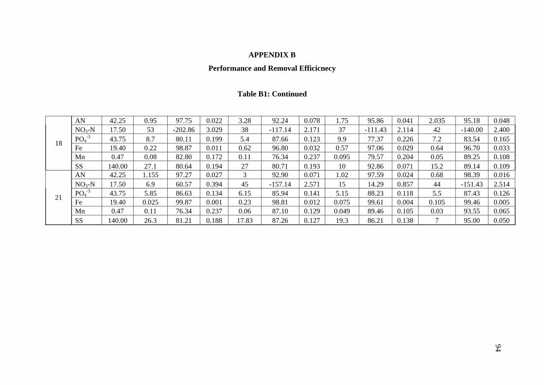
APPENDIX B
Performance and Removal Efficicnecy
Table B1: Continued
AN 42.25 0.95 97.75 0.022 3.28 92.24 0.078 1.75 95.86 0.041 2.035 95.18 0.048 NO3-N 17.50 53 -202.86 3.029 38 -117.14 2.171 37 -111.43 2.114 42 -140.00 2.400 PO4
-3 43.75 8.7 80.11 0.199 5.4 87.66 0.123 9.9 77.37 0.226 7.2 83.54 0.165 Fe 19.40 0.22 98.87 0.011 0.62 96.80 0.032 0.57 97.06 0.029 0.64 96.70 0.033 Mn 0.47 0.08 82.80 0.172 0.11 76.34 0.237 0.095 79.57 0.204 0.05 89.25 0.108
18
SS 140.00 27.1 80.64 0.194 27 80.71 0.193 10 92.86 0.071 15.2 89.14 0.109 AN 42.25 1.155 97.27 0.027 3 92.90 0.071 1.02 97.59 0.024 0.68 98.39 0.016 NO3-N 17.50 6.9 60.57 0.394 45 -157.14 2.571 15 14.29 0.857 44 -151.43 2.514 PO4
-3 43.75 5.85 86.63 0.134 6.15 85.94 0.141 5.15 88.23 0.118 5.5 87.43 0.126 Fe 19.40 0.025 99.87 0.001 0.23 98.81 0.012 0.075 99.61 0.004 0.105 99.46 0.005 Mn 0.47 0.11 76.34 0.237 0.06 87.10 0.129 0.049 89.46 0.105 0.03 93.55 0.065
21
SS 140.00 26.3 81.21 0.188 17.83 87.26 0.127 19.3 86.21 0.138 7 95.00 0.050
94
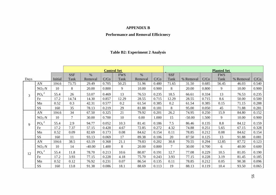
APPENDIX B
Performance and Removal Efficicnecy
Table B2: Experiment 2 Analysis
Control Set Planted Set
Days Initial SSF Tank
% Removal C/Co
FWS Tank
% Removal C/Co
SSF Tank % Removal C/Co
FWS Tank % Removal C/Co
AN 104.6 73.75 29.49 0.705 50.25 51.96 0.480 71.65 31.50 0.685 56.45 46.03 0.540 NO3-N 10 8 20.00 0.800 9 10.00 0.900 8 20.00 0.800 9 10.00 0.900 PO4
-3 55.4 26 53.07 0.469 13 76.53 0.235 18.5 66.61 0.334 13 76.53 0.235 Fe 17.2 14.74 14.30 0.857 12.29 28.55 0.715 12.29 28.55 0.715 8.6 50.00 0.500 Mn 0.52 0.3 42.31 0.577 0.2 61.54 0.385 0.2 61.54 0.385 0.15 71.15 0.288
3
SS 160 35 78.13 0.219 29 81.88 0.181 8 95.00 0.050 45 71.88 0.281 AN 104.6 34 67.50 0.325 21 79.92 0.201 26.2 74.95 0.250 15.9 84.80 0.152 NO3-N 10 7 30.00 0.700 10 0.00 1.000 15 -50.00 1.500 9 10.00 0.900 PO4
-3 55.4 2.9 94.77 0.052 10.3 81.41 0.186 7.5 86.46 0.135 8.8 84.12 0.159 Fe 17.2 7.37 57.15 0.428 4.67 72.85 0.272 4.32 74.88 0.251 5.65 67.15 0.328 Mn 0.52 0.09 82.69 0.173 0.08 84.62 0.154 0.11 78.85 0.212 0.08 84.62 0.154
9
SS 160 11 93.13 0.069 17 89.38 0.106 20 87.50 0.125 13 91.88 0.081 AN 104.6 38.5 63.19 0.368 21.1 79.83 0.202 30.8 70.55 0.294 12.85 87.72 0.123 NO3-N 10 14 -40.00 1.400 8 20.00 0.800 7 30.00 0.700 6 40.00 0.600 PO4
-3 55.4 11.8 78.70 0.213 10.6 80.87 0.191 12.7 77.08 0.229 10.5 81.05 0.190 Fe 17.2 3.93 77.15 0.228 4.18 75.70 0.243 3.93 77.15 0.228 3.19 81.45 0.185 Mn 0.52 0.12 76.92 0.231 0.07 86.54 0.135 0.11 78.85 0.212 0.05 90.38 0.096
12
SS 160 13.8 91.38 0.086 18.1 88.69 0.113 19 88.13 0.119 10.4 93.50 0.065
95
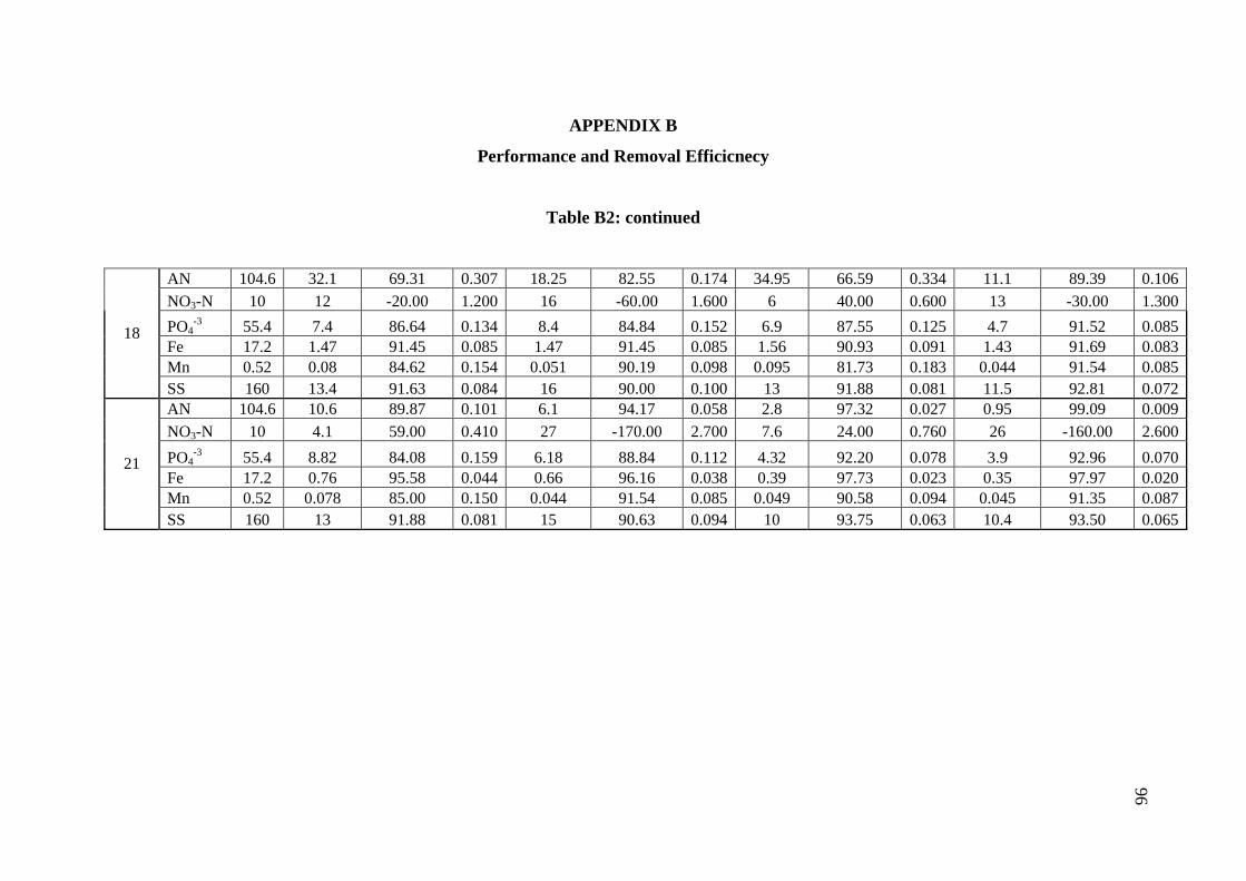
APPENDIX B
Performance and Removal Efficicnecy
Table B2: continued
AN 104.6 32.1 69.31 0.307 18.25 82.55 0.174 34.95 66.59 0.334 11.1 89.39 0.106 NO3-N 10 12 -20.00 1.200 16 -60.00 1.600 6 40.00 0.600 13 -30.00 1.300 PO4
-3 55.4 7.4 86.64 0.134 8.4 84.84 0.152 6.9 87.55 0.125 4.7 91.52 0.085 Fe 17.2 1.47 91.45 0.085 1.47 91.45 0.085 1.56 90.93 0.091 1.43 91.69 0.083 Mn 0.52 0.08 84.62 0.154 0.051 90.19 0.098 0.095 81.73 0.183 0.044 91.54 0.085
18
SS 160 13.4 91.63 0.084 16 90.00 0.100 13 91.88 0.081 11.5 92.81 0.072 AN 104.6 10.6 89.87 0.101 6.1 94.17 0.058 2.8 97.32 0.027 0.95 99.09 0.009 NO3-N 10 4.1 59.00 0.410 27 -170.00 2.700 7.6 24.00 0.760 26 -160.00 2.600 PO4
-3 55.4 8.82 84.08 0.159 6.18 88.84 0.112 4.32 92.20 0.078 3.9 92.96 0.070 Fe 17.2 0.76 95.58 0.044 0.66 96.16 0.038 0.39 97.73 0.023 0.35 97.97 0.020 Mn 0.52 0.078 85.00 0.150 0.044 91.54 0.085 0.049 90.58 0.094 0.045 91.35 0.087
21
SS 160 13 91.88 0.081 15 90.63 0.094 10 93.75 0.063 10.4 93.50 0.065
96
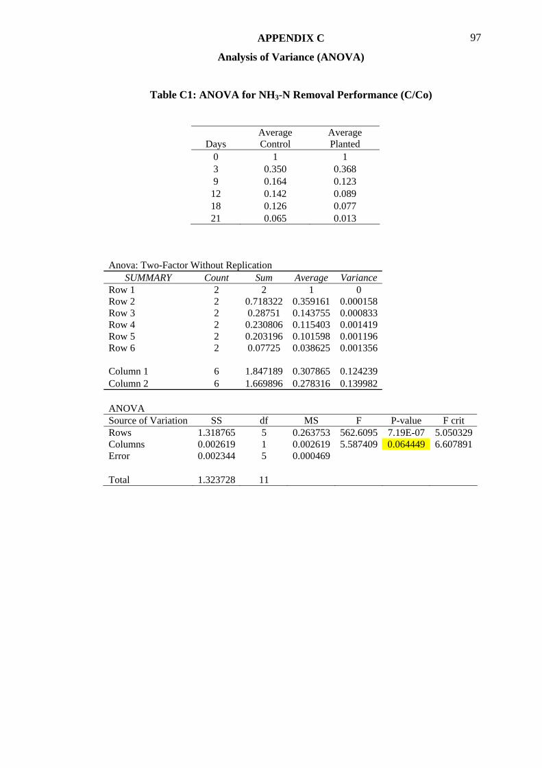
APPENDIX C 97
Analysis of Variance (ANOVA)
Table C1: ANOVA for NH3-N Removal Performance (C/Co)
Days Average Control
Average Planted
0 1 1 3 0.350 0.368 9 0.164 0.123
12 0.142 0.089 18 0.126 0.077 21 0.065 0.013
Anova: Two-Factor Without Replication SUMMARY Count Sum Average Variance
Row 1 2 2 1 0 Row 2 2 0.718322 0.359161 0.000158 Row 3 2 0.28751 0.143755 0.000833 Row 4 2 0.230806 0.115403 0.001419 Row 5 2 0.203196 0.101598 0.001196 Row 6 2 0.07725 0.038625 0.001356 Column 1 6 1.847189 0.307865 0.124239 Column 2 6 1.669896 0.278316 0.139982 ANOVA Source of Variation SS df MS F P-value F crit Rows 1.318765 5 0.263753 562.6095 7.19E-07 5.050329Columns 0.002619 1 0.002619 5.587409 0.064449 6.607891Error 0.002344 5 0.000469 Total 1.323728 11
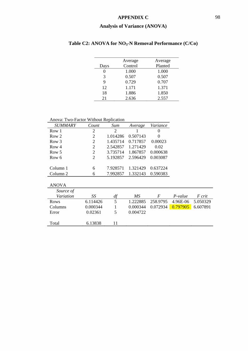
APPENDIX C 98
Analysis of Variance (ANOVA)
Table C2: ANOVA for NO3-N Removal Performance (C/Co)
Days Average Control
Average Planted
0 1.000 1.000 3 0.507 0.507 9 0.729 0.707
12 1.171 1.371 18 1.886 1.850 21 2.636 2.557
Anova: Two-Factor Without Replication SUMMARY Count Sum Average Variance
Row 1 2 2 1 0 Row 2 2 1.014286 0.507143 0 Row 3 2 1.435714 0.717857 0.00023 Row 4 2 2.542857 1.271429 0.02 Row 5 2 3.735714 1.867857 0.000638 Row 6 2 5.192857 2.596429 0.003087 Column 1 6 7.928571 1.321429 0.637224 Column 2 6 7.992857 1.332143 0.590383 ANOVA
Source of Variation SS df MS F P-value F crit
Rows 6.114426 5 1.222885 258.9795 4.96E-06 5.050329Columns 0.000344 1 0.000344 0.072934 0.797905 6.607891Error 0.02361 5 0.004722 Total 6.13838 11
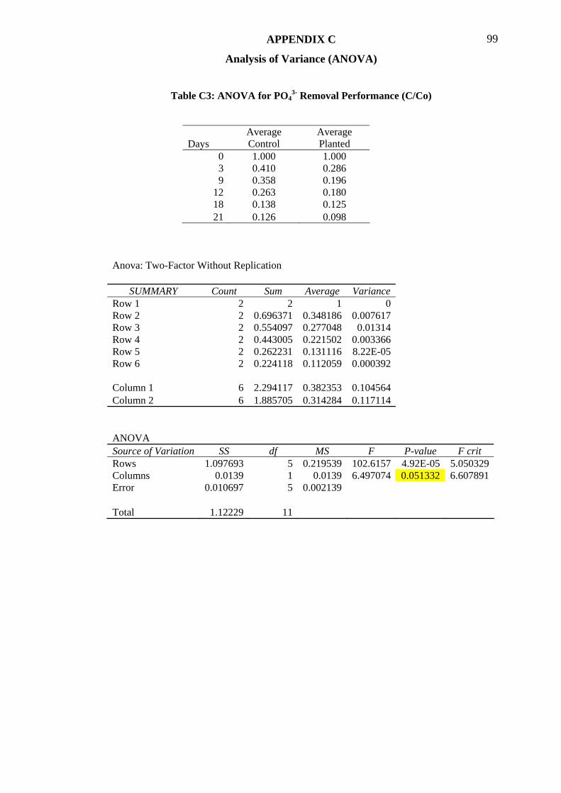
APPENDIX C 99
Analysis of Variance (ANOVA)
Table C3: ANOVA for PO43- Removal Performance (C/Co)
Days Average Control
Average Planted
0 1.000 1.000 3 0.410 0.286 9 0.358 0.196
12 0.263 0.180 18 0.138 0.125 21 0.126 0.098
Anova: Two-Factor Without Replication
SUMMARY Count Sum Average Variance Row 1 2 2 1 0 Row 2 2 0.696371 0.348186 0.007617 Row 3 2 0.554097 0.277048 0.01314 Row 4 2 0.443005 0.221502 0.003366 Row 5 2 0.262231 0.131116 8.22E-05 Row 6 2 0.224118 0.112059 0.000392 Column 1 6 2.294117 0.382353 0.104564 Column 2 6 1.885705 0.314284 0.117114 ANOVA Source of Variation SS df MS F P-value F crit Rows 1.097693 5 0.219539 102.6157 4.92E-05 5.050329Columns 0.0139 1 0.0139 6.497074 0.051332 6.607891Error 0.010697 5 0.002139 Total 1.12229 11
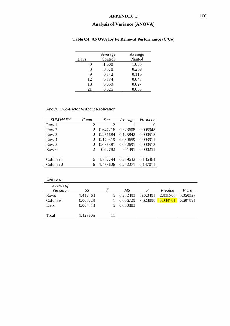
APPENDIX C 100
Analysis of Variance (ANOVA)
Table C4: ANOVA for Fe Removal Performance (C/Co)
Days Average Control
Average Planted
0 1.000 1.000 3 0.378 0.269 9 0.142 0.110
12 0.134 0.045 18 0.059 0.027 21 0.025 0.003
Anova: Two-Factor Without Replication
SUMMARY Count Sum Average Variance Row 1 2 2 1 0 Row 2 2 0.647216 0.323608 0.005948 Row 3 2 0.251684 0.125842 0.000518 Row 4 2 0.179319 0.089659 0.003911 Row 5 2 0.085381 0.042691 0.000513 Row 6 2 0.02782 0.01391 0.000251 Column 1 6 1.737794 0.289632 0.136364 Column 2 6 1.453626 0.242271 0.147011 ANOVA
Source of Variation SS df MS F P-value F crit
Rows 1.412463 5 0.282493 320.0491 2.93E-06 5.050329Columns 0.006729 1 0.006729 7.623898 0.039781 6.607891Error 0.004413 5 0.000883 Total 1.423605 11
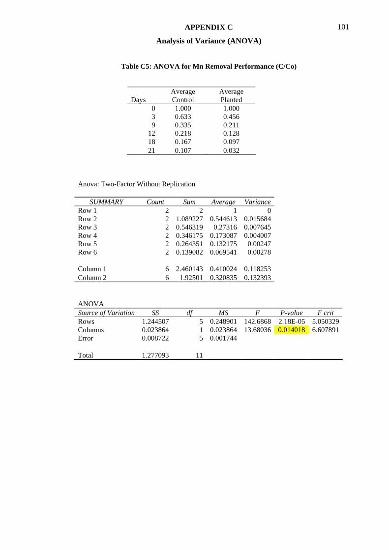
APPENDIX C 101
Analysis of Variance (ANOVA)
Table C5: ANOVA for Mn Removal Performance (C/Co)
Days Average Control
Average Planted
0 1.000 1.000 3 0.633 0.456 9 0.335 0.211
12 0.218 0.128 18 0.167 0.097 21 0.107 0.032
Anova: Two-Factor Without Replication
SUMMARY Count Sum Average Variance Row 1 2 2 1 0 Row 2 2 1.089227 0.544613 0.015684 Row 3 2 0.546319 0.27316 0.007645 Row 4 2 0.346175 0.173087 0.004007 Row 5 2 0.264351 0.132175 0.00247 Row 6 2 0.139082 0.069541 0.00278 Column 1 6 2.460143 0.410024 0.118253 Column 2 6 1.92501 0.320835 0.132393 ANOVA Source of Variation SS df MS F P-value F crit Rows 1.244507 5 0.248901 142.6868 2.18E-05 5.050329Columns 0.023864 1 0.023864 13.68036 0.014018 6.607891Error 0.008722 5 0.001744 Total 1.277093 11
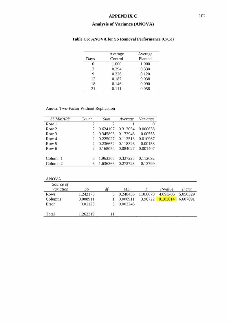
APPENDIX C 102
Analysis of Variance (ANOVA)
Table C6: ANOVA for SS Removal Performance (C/Co)
Days Average Control
Average Planted
0 1.000 1.000 3 0.294 0.330 9 0.226 0.120
12 0.187 0.038 18 0.146 0.090 21 0.111 0.058
Anova: Two-Factor Without Replication
SUMMARY Count Sum Average Variance Row 1 2 2 1 0 Row 2 2 0.624107 0.312054 0.000638 Row 3 2 0.345893 0.172946 0.00555 Row 4 2 0.225027 0.112513 0.010967 Row 5 2 0.236652 0.118326 0.00158 Row 6 2 0.168054 0.084027 0.001407 Column 1 6 1.963366 0.327228 0.112692 Column 2 6 1.636366 0.272728 0.13799 ANOVA
Source of Variation SS df MS F P-value F crit
Rows 1.242178 5 0.248436 110.6078 4.09E-05 5.050329Columns 0.008911 1 0.008911 3.96722 0.103014 6.607891Error 0.01123 5 0.002246 Total 1.262319 11