ptg manual v2.0
TRANSCRIPT

8/6/2019 PTG Manual V2.0
http://slidepdf.com/reader/full/ptg-manual-v20 1/17

8/6/2019 PTG Manual V2.0
http://slidepdf.com/reader/full/ptg-manual-v20 2/17
PTG Manual V2.0`
2
PACKING LIST
FT3 Thickness Gauge2000µm Check Gauge500 µm Check GaugeBulls Eye Spirit LevelFoot adjustment spanner
OPTIONAL EXTRAS
Hanatek Results PrinterAutomatic Sample FeederAdditional Downforce weights (FT3-v)Footswitch
8/6/2019 PTG Manual V2.0
http://slidepdf.com/reader/full/ptg-manual-v20 3/17
PTG Manual V2.0`
3
WARNING – THE HANATEK FT3 HAS MOVING PARTS WHICH MAYCONSTITUTE A PINCHING RISK FOR FINGERS.
REASONABLE CARE MUST BE TAKEN AT ALL TIMES – DO NOTTOUCH THE MOVING PARTS DURING OPERATION AND ENSUREHAIR AND CLOTHING IS KEPT CLEAR.
ASSEMBLY
1.0 Unpack the unit carefully and check the contents against the packing list.
2.0 Place the instrument on a suitable bench.
Avoid using the instrument in areas where vibration may affect thereadings; i.e. close to heavy machinery.
Changes in temperature will affect instrument readings as the metalworkin the instrument will expand and contract
-Avoid placing in direct sunlight.-For best results use in a temperature controlled environment
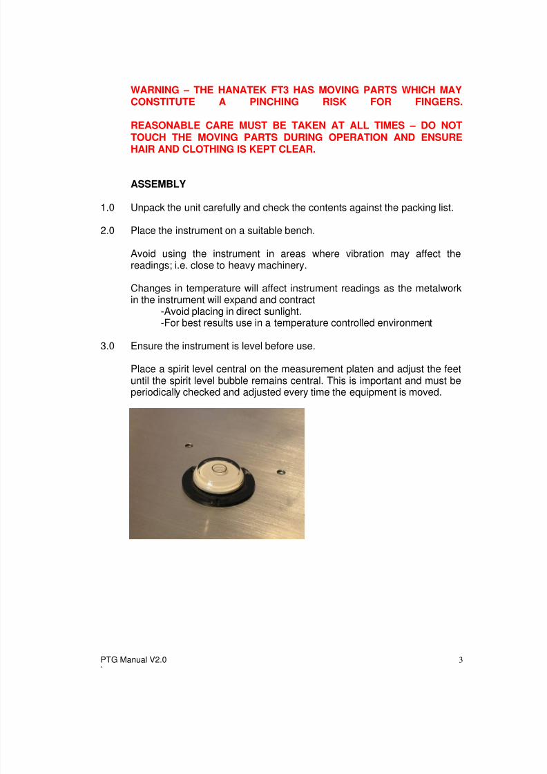
3.0 Ensure the instrument is level before use.
Place a spirit level central on the measurement platen and adjust the feetuntil the spirit level bubble remains central. This is important and must beperiodically checked and adjusted every time the equipment is moved.
8/6/2019 PTG Manual V2.0
http://slidepdf.com/reader/full/ptg-manual-v20 4/17
PTG Manual V2.0`
4
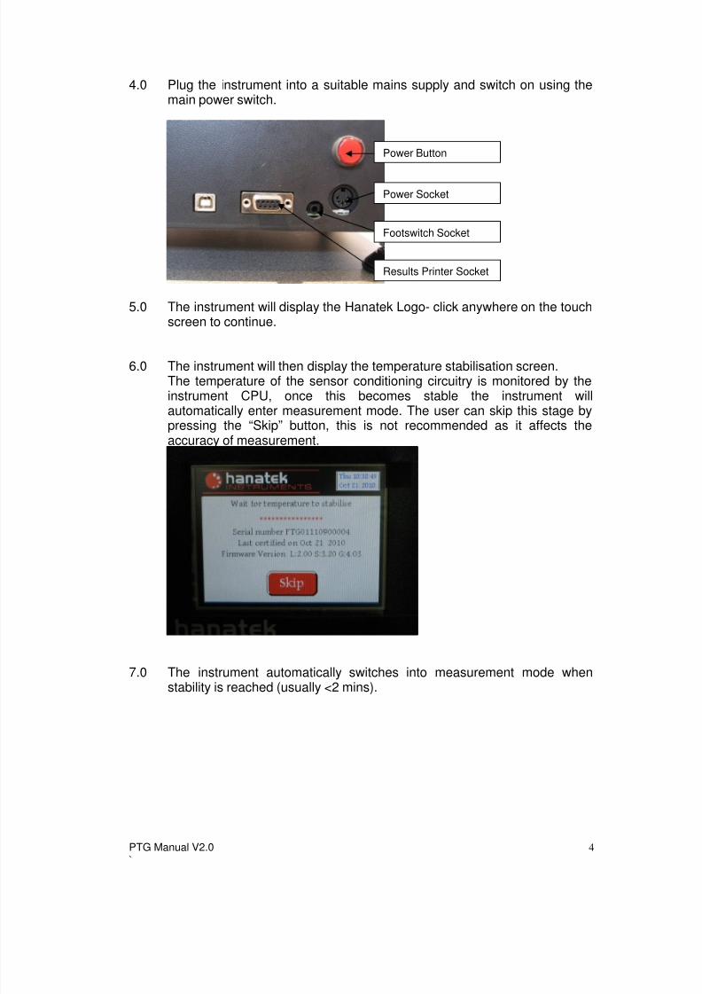
4.0 Plug the instrument into a suitable mains supply and switch on using themain power switch.
5.0 The instrument will display the Hanatek Logo- click anywhere on the touchscreen to continue.
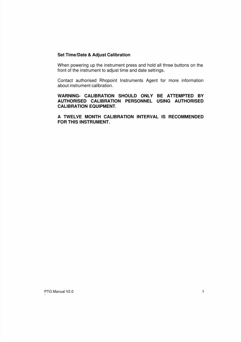
6.0 The instrument will then display the temperature stabilisation screen.The temperature of the sensor conditioning circuitry is monitored by theinstrument CPU, once this becomes stable the instrument willautomatically enter measurement mode. The user can skip this stage bypressing the “Skip” button, this is not recommended as it affects theaccuracy of measurement.
7.0 The instrument automatically switches into measurement mode whenstability is reached (usually <2 mins).
Power Button
Power Socket
Footswitch Socket
Results Printer Socket
8/6/2019 PTG Manual V2.0
http://slidepdf.com/reader/full/ptg-manual-v20 5/17
PTG Manual V2.0`
5
Set Time/Date & Adjust Calibration
When powering up the instrument press and hold all three buttons on thefront of the instrument to adjust time and date settings.
Contact authorised Rhopoint Instruments Agent for more informationabout instrument calibration.
WARNING- CALIBRATION SHOULD ONLY BE ATTEMPTED BYAUTHORISED CALIBRATION PERSONNEL USING AUTHORISEDCALIBRATION EQUIPMENT.
A TWELVE MONTH CALIBRATION INTERVAL IS RECOMMENDEDFOR THIS INSTRUMENT.
8/6/2019 PTG Manual V2.0
http://slidepdf.com/reader/full/ptg-manual-v20 6/17
PTG Manual V2.0`
6
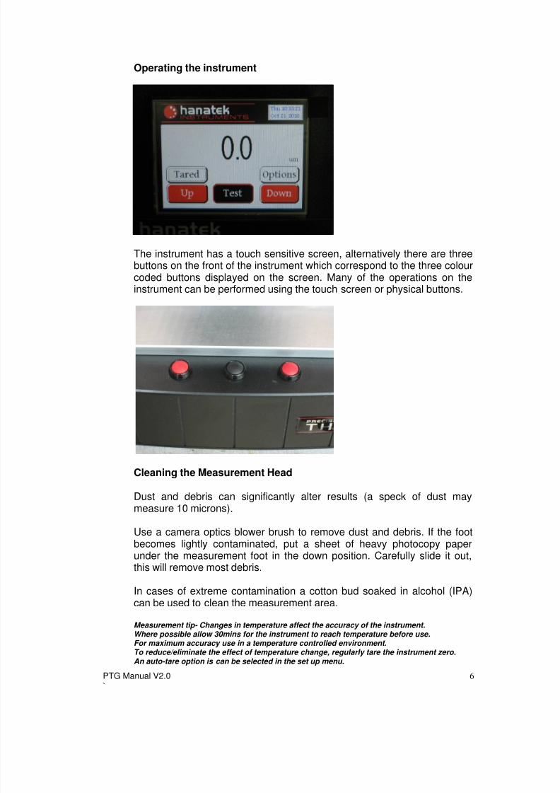
Operating the instrument
The instrument has a touch sensitive screen, alternatively there are threebuttons on the front of the instrument which correspond to the three colour
coded buttons displayed on the screen. Many of the operations on theinstrument can be performed using the touch screen or physical buttons.
Cleaning the Measurement Head
Dust and debris can significantly alter results (a speck of dust maymeasure 10 microns).
Use a camera optics blower brush to remove dust and debris. If the footbecomes lightly contaminated, put a sheet of heavy photocopy paper
under the measurement foot in the down position. Carefully slide it out,this will remove most debris.
In cases of extreme contamination a cotton bud soaked in alcohol (IPA)can be used to clean the measurement area.
Measurement tip- Changes in temperature affect the accuracy of the instrument.Where possible allow 30mins for the instrument to reach temperature before use.For maximum accuracy use in a temperature controlled environment.To reduce/eliminate the effect of temperature change, regularly tare the instrument zero.An auto-tare option is can be selected in the set up menu.
8/6/2019 PTG Manual V2.0
http://slidepdf.com/reader/full/ptg-manual-v20 7/17
PTG Manual V2.0`
7
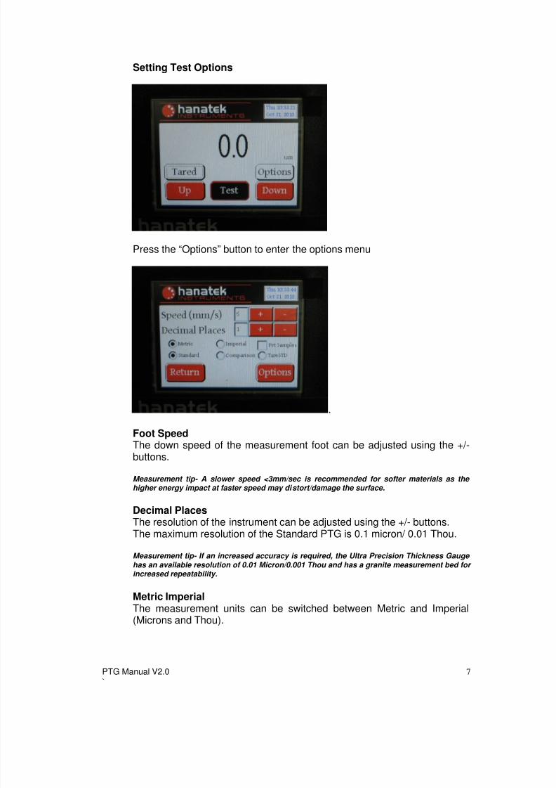
Setting Test Options
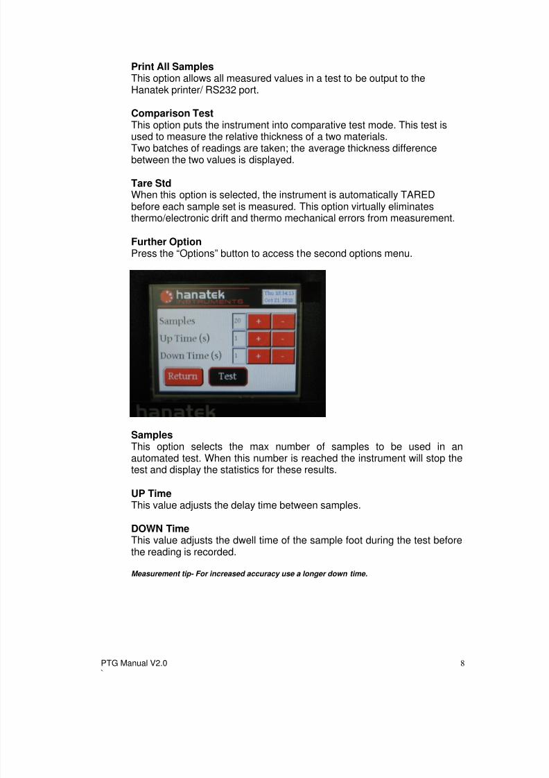
Press the “Options” button to enter the options menu
.Foot SpeedThe down speed of the measurement foot can be adjusted using the +/-buttons.
Measurement tip- A slower speed <3mm/sec is recommended for softer materials as the higher energy impact at faster speed may distort/damage the surface.
Decimal PlacesThe resolution of the instrument can be adjusted using the +/- buttons.The maximum resolution of the Standard PTG is 0.1 micron/ 0.01 Thou.
Measurement tip- If an increased accuracy is required, the Ultra Precision Thickness Gauge has an available resolution of 0.01 Micron/0.001 Thou and has a granite measurement bed for increased repeatability.
Metric ImperialThe measurement units can be switched between Metric and Imperial(Microns and Thou).
8/6/2019 PTG Manual V2.0
http://slidepdf.com/reader/full/ptg-manual-v20 8/17
PTG Manual V2.0`
8
Print All SamplesThis option allows all measured values in a test to be output to theHanatek printer/ RS232 port.
Comparison TestThis option puts the instrument into comparative test mode. This test isused to measure the relative thickness of a two materials.Two batches of readings are taken; the average thickness differencebetween the two values is displayed.
Tare StdWhen this option is selected, the instrument is automatically TAREDbefore each sample set is measured. This option virtually eliminatesthermo/electronic drift and thermo mechanical errors from measurement.
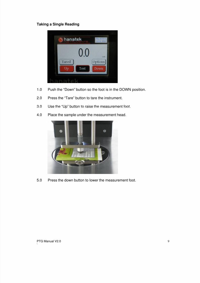
Further OptionPress the “Options” button to access the second options menu.
SamplesThis option selects the max number of samples to be used in anautomated test. When this number is reached the instrument will stop thetest and display the statistics for these results.
UP Time This value adjusts the delay time between samples.
DOWN Time
This value adjusts the dwell time of the sample foot during the test beforethe reading is recorded.
Measurement tip- For increased accuracy use a longer down time.
8/6/2019 PTG Manual V2.0
http://slidepdf.com/reader/full/ptg-manual-v20 9/17
PTG Manual V2.0`
9
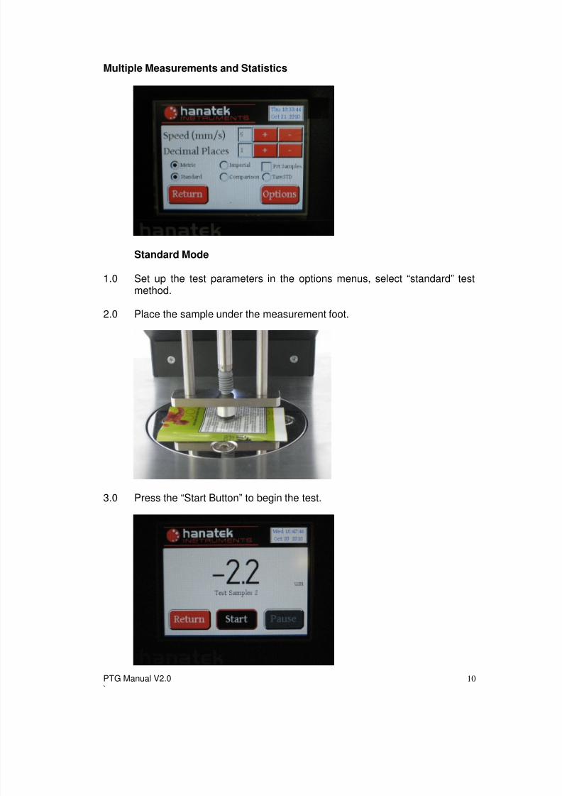
Taking a Single Reading
1.0 Push the “Down” button so the foot is in the DOWN position.
2.0 Press the “Tare” button to tare the instrument.3.0 Use the “Up” button to raise the measurement foot.
4.0 Place the sample under the measurement head.
5.0 Press the down button to lower the measurement foot.
8/6/2019 PTG Manual V2.0
http://slidepdf.com/reader/full/ptg-manual-v20 10/17
PTG Manual V2.0`
10
Multiple Measurements and Statistics
Standard Mode
1.0 Set up the test parameters in the options menus, select “standard” testmethod.
2.0 Place the sample under the measurement foot.
3.0 Press the “Start Button” to begin the test.
8/6/2019 PTG Manual V2.0
http://slidepdf.com/reader/full/ptg-manual-v20 11/17
PTG Manual V2.0`
11
4.0 When the foot is in the up position the sample can be repositioned(measuring the average thickness of a single sample) or replaced(measuring the average thickness of a sample set).
5.0 Press “Pause” to pause the test.
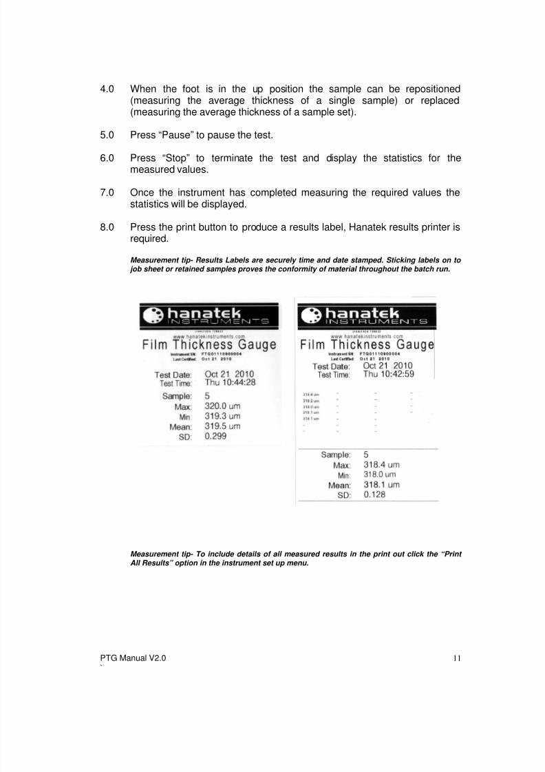
6.0 Press “Stop” to terminate the test and display the statistics for themeasured values.
7.0 Once the instrument has completed measuring the required values thestatistics will be displayed.
8.0 Press the print button to produce a results label, Hanatek results printer isrequired.
Measurement tip- Results Labels are securely time and date stamped. Sticking labels on to
job sheet or retained samples proves the conformity of material throughout the batch run.
Measurement tip- To include details of all measured results in the print out click the “Print All Results” option in the instrument set up menu.
8/6/2019 PTG Manual V2.0
http://slidepdf.com/reader/full/ptg-manual-v20 12/17
PTG Manual V2.0`
12
Comparative Mode
1.0 Comparative test allows the average difference to be measured betweentwo different samples.
2.0 Set up the test parameters in the options menus, select “comparative” testmethod.
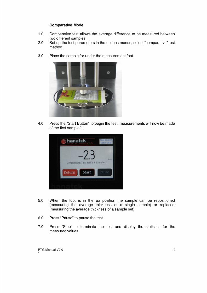
3.0 Place the sample for under the measurement foot.
4.0 Press the “Start Button” to begin the test, measurements will now be madeof the first sample/s.
5.0 When the foot is in the up position the sample can be repositioned
(measuring the average thickness of a single sample) or replaced(measuring the average thickness of a sample set).
6.0 Press “Pause” to pause the test.
7.0 Press “Stop” to terminate the test and display the statistics for themeasured values.
8/6/2019 PTG Manual V2.0
http://slidepdf.com/reader/full/ptg-manual-v20 13/17
PTG Manual V2.0`
13
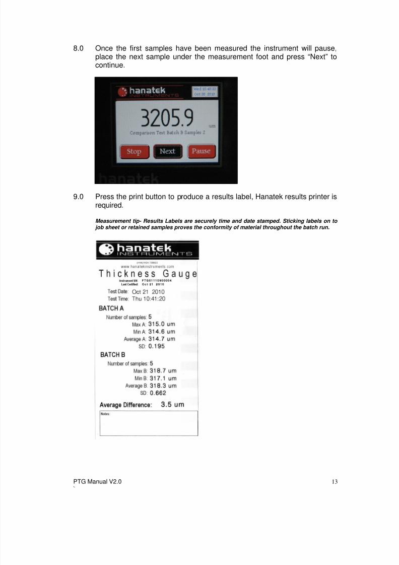
8.0 Once the first samples have been measured the instrument will pause,place the next sample under the measurement foot and press “Next” tocontinue.
9.0 Press the print button to produce a results label, Hanatek results printer isrequired.
Measurement tip- Results Labels are securely time and date stamped. Sticking labels on to job sheet or retained samples proves the conformity of material throughout the batch run.
8/6/2019 PTG Manual V2.0
http://slidepdf.com/reader/full/ptg-manual-v20 14/17
PTG Manual V2.0`
14
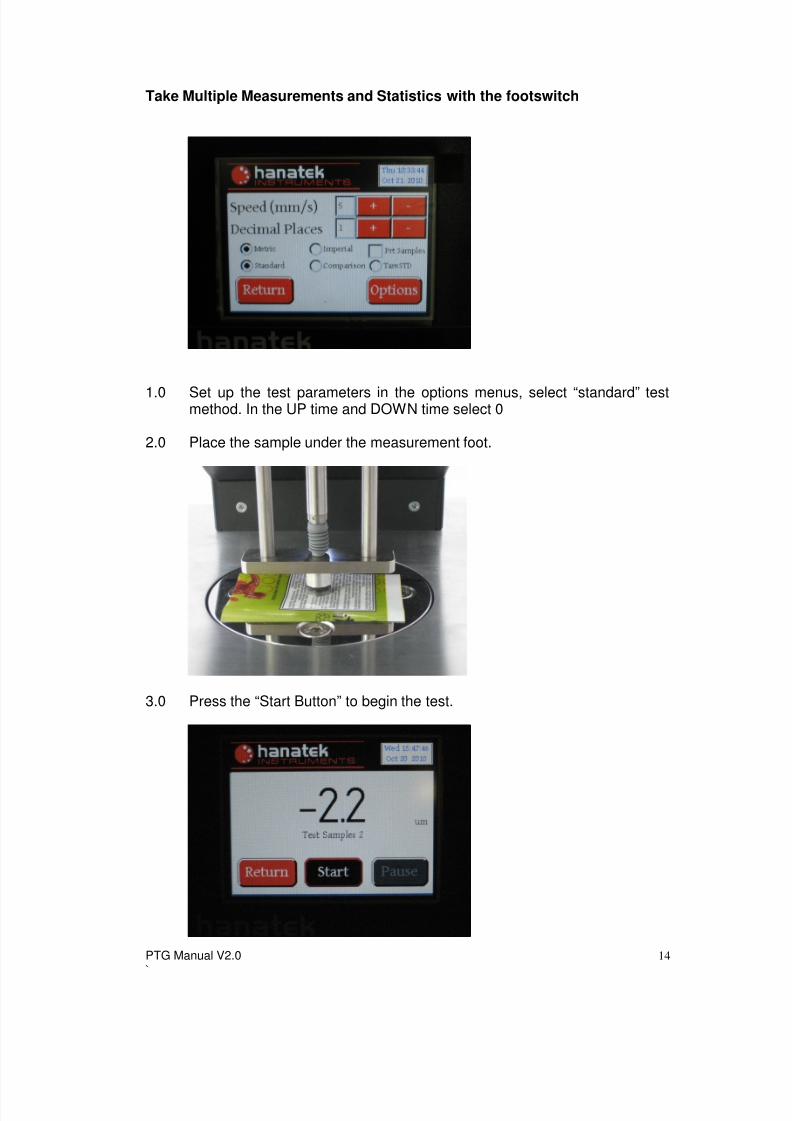
Take Multiple Measurements and Statistics with the footswitch
1.0 Set up the test parameters in the options menus, select “standard” testmethod. In the UP time and DOWN time select 0
2.0 Place the sample under the measurement foot.
3.0 Press the “Start Button” to begin the test.

8/6/2019 PTG Manual V2.0
http://slidepdf.com/reader/full/ptg-manual-v20 15/17
PTG Manual V2.0`
15
4.0 Press the footswitch to lower the measurement foot.
5.0 Once a stable reading is reached release the footswitch to raise themeasurement foot. Reposition the sample and repeat as necessary.
6.0 Press “Pause” to pause the test.
7.0 Press “Stop” to terminate the test and display the statistics for themeasured values.
8.0 Once the instrument has completed measuring the required values thestatistics will be displayed.
9.0 Press the print button to produce a results label, Hanatek results printer isrequired.
Measurement tip- Results Labels are securely time and date stamped. Sticking labels on to job sheet or retained samples proves the conformity of material throughout the batch run.
Measurement tip- To include details of all measured results in the print out click the “Print All Results” option in the instrument set up menu.

8/6/2019 PTG Manual V2.0
http://slidepdf.com/reader/full/ptg-manual-v20 16/17
PTG Manual V2.0`
16
.
SERVICE
Contact- HANATEK Instruments:
Telephone No: +44 (0)1424 739623
Fax Number: +44 (0)1424 730600
E-mail: [email protected] Site: www.hanatekinstruments.com

8/6/2019 PTG Manual V2.0
http://slidepdf.com/reader/full/ptg-manual-v20 17/17
PTG Manual V2.0`
17
EU Directive 2002/96/EC on WEEE (Waste Electrical & Electronic Equipment) andRoHS (Restriction of the use of certain Hazardous Substances).
The European Union's Directive on Restriction of the use of certain HazardousSubstances in electrical and electronic equipment (ROHS) defines each of 10categories of electrical and electronic equipment in Annex I . Category 9 isdefined as follows:
9. Monitoring and control instrumentsSmoke detector Heating regulatorsThermostatsMeasuring, weighing, or adjusting appliances for household or aslaboratory equipmentOther monitoring and control instruments used in industrial installations(e.g. in control panels).
The RoHS Directive defines the scope of restrictions in Article 2 as follows:
"1. Without prejudice to Article 6, this Directive shall apply to electrical andelectronic equipment falling under the categories I, 2, 3, 4, 5, 6, 7 and 10 set outin Annex IA to Directive No 2002/96/EC (WEEE) and to electric light bulbs, andluminaires in households."
This product is supplied as a Monitoring and Control instrument and as such fallswithin category 9 of the EU directive 2002/96/EC and so is excluded fromrestrictions under the scope of the RoHS Directive.
The Waste Electrical and Electronic Equipment Directive is intended to reducethe amount of harmful substances that are added to the environment by theinappropriate disposal of these products through municipal waste.
Some of the materials contained in electrical and electronic products candamage the environment and are potentially hazardous to human health; for this reason the products are marked with the crossed out wheelie bin symbolwhich indicates that they must not be disposed of via unsorted municipal waste.
Rhopoint Instruments Ltd have arranged a means for our customers to haveproducts that have reached the end of their useful life safely recycled. Weencourage all end users to us at the end of the product's life to return their purchase to as for recycling as per Article 9 of the WEEE Directive.
Please contact us on +44 (0) 1424-739622 and we will advise on the process for returning these waste products so we can all contribute to the safe recycling ofthese materials.