predicting turbulent flow in a staggered tube...
TRANSCRIPT
PREDICTING TURBULENT FLOW IN A STAGGERED TUBE
MOHD ADIB MUIZZUDDIN BIN MOHLIS
Laporan ini dikemukakan sebagai
Memenuhi sebahagian daripada syarat penganugerahan
Ijazah Sarjana Muda Kejuruteraan Mekanikal (Termal-Bendalir)
Fakulti Kejuruteraan Mekanikal
Universiti Teknikal Malaysia Melaka
September 2007
‘Saya/Kami* akui bahawa telah membaca
karya ini dan pada pandangan saya/kami* karya ini
adalah memadai dari segi skop dan kualiti untuk tujuan penganugerahan
Ijazah Sarjana Muda Kejuruteraan Mekanikal (Termal-Bendalir)’
Tandatangan :…………………………………..
Nama Penyelia I:………………………………..
Tarikh :………………………………………….
Tandatangan:……………………………………
Nama Penyelia II:………………………………
Tarikh:………………………………………….
i
Saya akui laporan ini adalah hasil kerja saya sendiri kecuali ringkasan dan
petikan yang tiap-tiap satunya saya telah jelaskan sumbernya”
Tandatangan :……………………………..
Nama Penulis :……………………………
Tarikh :……………………………………
ii
ACKNOWLEDGEMENT
Alhamdulillah, thanks to ALLAH because I have completed my Projek
Sarjana Muda 1 without facing any major problem.
First and foremost I would like to deliver my deep appreciation and thankful
my supervisor which is my Heat Transfer Subject lecturer, Encik Shamsul Bahari
Bin Azraai for being such a great mentor to me. Much thank and gratitude to Encik
Ahmad Kamal Bin Mat Yamin, Mechanical Engineering supervisor for Projek
Sarjana Muda, for his good concern. I also would like to thanks my family for
encourage and motivate me during this period of industrial training. Besides that I
also would like to thank them for financial support.
Lastly, thanks to Faculty of Mechanical Engineering which has gave an
opportunity to discover Mechanical Engineering Field. I hope this report will be used
by other students as a reference for their project.
iii
ABSTRACT
This report is about predicting turbulent flow in a staggered tube using
Computational Fluid Dynamic software developed by Ansys which is the CFX.
Either CFX, there are many non computational dynamic methods that can predict the
heat transfer and flow characteristic such experimental and analytical method. But
using Computer Fluid Dynamic software can save time and cost because only virtual
model were create and simulate. The aims of this study are to predict the fluid flow
and heat transfer characteristic in a staggered tube air and water as the fluid. The
flow and heat transfer characteristic of a staggered tube a nearly the same of a single
cylinder/tube. The first row characteristic is usually the same as a single tube. But for
the second row and so on, the characteristic are depends on the rows that’s come
first. For a single tube actually there are two boundary layers which occur at front of
the tube and the back of the tube. Laminar boundary layer always developed at the
front while turbulent at the back. Several geometrical parameters have been defined
according to the previous research (journals) done in order to design the staggered
tube geometry. The other parameters such as the fluid velocity and temperature are
also defined according to the previous research. With these parameters a simulation
can be made using CFX. There are several process in CFX which are the CFX Pre-
processing, CFX solver and CFX post processing. The results obtain are in terms of
velocity, temperature and pressure profile. From the investigation lower value of
pitch used will results better heat transfer rate. When the pitch value is decrease, the
pressure drop will rise and thus will increase the heat transfer rate. In engineering
application higher pressure drop value will result higher power required to move the
fluid through the tube bank.
iv
ABSTRAK
Laporan ini menceritakan tentang meramal dan mentafsir aliran bergelora di
dalam tiub yang disusun secara berperingkat dengan menggunakan perisian
pengkomputeran aliran dinamik iaitu Ansys CFX. Selain CFX, terdapat kaedah-
kaedah lain yang boleh meramal dan mentafsir pemindahan haba dan sifat aliran
seperti kaedah pengujian dan analitikal. Tetapi dengan menggunakan kaedah
pengkomputeran aliran dinamik, masa dan kos dapat dijimatkan dan dikurangkan
berbanding dengan menggunakan dua kaedah yang disebut tadi. Ini adalah kerana
hanya model maya saja yang dicipta dan di kaji. Tujuan laporan ini adalah untuk
meramal dan mentafsir sifat aliran dan pemindahan haba didalam tiub berperingkat
dengan menggunakan air dan udara sebagai medium aliran. Sebenarnya sifat aliran
dan pemindahan haba didalam tiub berperingkat adalah hampir menyamai dengan
tiub tunggal. Ini adalah kerana pada barisan pertama sifatnya adalah seperti aliran
tunggal. Pada barisan kedua dan seterusnya sifatnya adalah bergantung kepada
barisan yang datang dahulu. Untuk tiub tunggal, terdapat dua lapisan sempadan yang
terbentuk di hadapan tiub dan dibelakang tiub. Lapisan laminar selalunya terbentuk
dihadapan manakala lapisan bergelora terbentuk di belakang. Beberapa parameter
geometri telah ditentukan berdasrkan kajian yang telah dijalankan oleh pengkaji-
pengkaji untuk mereka geometri tiub. Terdapat juga parameter lain yang telah di
tentukan seperti halaju bendalir dan suhu yang juga berdasrkan jurnal. Dengan
parameter-parameter ini simulasi dapat dilakukan dengan menggunakan CFX.
Terdapat beberapa process didalam CFX seperti CFX pra-proses, CFX penyelesai
dan CFX selepas proses. Keputusan yang diperolehi adalah didalam profil halaju,
suhu dan tekanan. Berdasarkan simulasi yang telah dijalankan, didapati nilai pitch
yang rendah akan meningkatkan kadar pemindahan haba. Tetapi apabila nilai pitch
berkurang, kejatuhan tekanan akan meningkat dan seterusnya meningkatkan kadar
pemindahan haba. Didalam aplikasi kejuruteraan, nilai kejatuhan tekanan yang tinggi
akan menyebabkan lebih banyak kuasa yang diperlukan untuk menggerakkan cecair
melalui tiub-tiub tersebut.
v
TABLE OF CONTENT
CHAPTER TITLE PAGE
PENGAKUAN
ACKNOWLEDGEMENT
ABSTRACT
ABSTRAK
TABLE OF CONTENT
LIST OF TABLES
LIST OF FIGURES
LIST OF SYMBOLS
LIST OF ABBREVIATONS
i
ii
iii
iv
v
viii
ix
xi
xiii
CHAPTER I INTRODUCTION 1
1.1 Predicting Turbulent in a Staggered Tube
1.2 Objective
1.3 Scope
1.4 Problem Statements
1
2
2
2
CHAPTER II LITERATURE REVIEW 4
2.1 Introduction 4
2.2 Computational Fluid Dynamic 5
2.3 Flow Across Cylinder 6
2.31 Drag Force 7
2.32 Correlation for Average Heat Transfer 9
2.4 Factors that Affect the Heat Transfer and Flow
Characteristic across a Cylinder
10
2.41 Boundary Layer 11
vi
CHAPTER TITLE
2.42 Flow Separation
PAGE
11
2.43 Adverse Pressure Gradient 11
2.44 Wake 12
2.45 Reynolds Number 12
2.5 Flow across Tube Bank 13
2.51 Heat Transfer Coefficient
2.6 Predicting the heat transfer and flow characteristic in a
staggered tube by Previous Researchers
2.61 Numerical/CFD simulation in a staggered tube
2.62 Analytical approach
15
16
17
21
CHAPTER III METHODOLOGY 25
CHAPTER IV
3.1 Introduction
3.2 Typical Stage of CFD
3.3 Steps to Generate CFD Simulations using Ansys CFX
3.4 Ansys Workbench
3.41 Geometry
3.42 Meshing
3.5 CFX Pre-Processing
3.51 Type of Simulation
3.52 Domain
3.53 Boundary Condition
3.54 Solver Control
3.6 CFX Solver
3.7 CFX Post Processing
RESULTS AND DISCUSSIONS
4.1 Temperature Profile
4.2 Velocity Profile
4.3 Pressure Profile
4.4 Velocity Vector and Streamline
25
25
26
27
27
29
31
31
32
32
33
33
33
34
34
39
42
47

vii
CHAPTER V CONCLUSION 50

viii
LIST OF TABLES
TABLE TITLES PAGE
2.1 Parameters used by Incropera et al for staggered
tube bank.
23
2.2 (a) Comparison of results for compact tube bank 24
2.2 (b) Comparison of results for wide tube bank
24
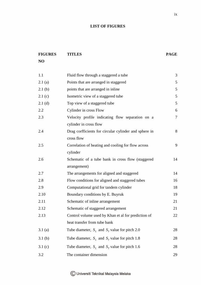
ix
LIST OF FIGURES
FIGURES
NO
TITLES PAGE
1.1 Fluid flow through a staggered a tube 3
2.1 (a) Points that are arranged in staggered 5
2.1 (b) points that are arranged in inline 5
2.1 (c) Isometric view of a staggered tube 5
2.1 (d) Top view of a staggered tube 5
2.2 Cylinder in cross Flow 6
2.3 Velocity profile indicating flow separation on a
cylinder in cross flow
7
2.4 Drag corfficients for circular cylinder and sphere in
cross flow
8
2.5 Correlation of heating and cooling for flow across
cylinder
9
2.6 Schematic of a tube bank in cross flow (staggered
arrangement)
14
2.7 The arrangements for aligned and staggered 14
2.8 Flow conditions for aligned and staggered tubes 16
2.9 Computational grid for tandem cylinder 18
2.10 Boundary conditions by E. Buyruk 19
2.11 Schematic of inline arrangement 21
2.12 Schematic of staggered arrangement 21
2.13 Control volume used by Khan et al for prediction of
heat transfer from tube bank
22
3.1 (a) Tube diameter, LS and TS value for pitch 2.0 28
3.1 (b) Tube diameter, LS and TS value for pitch 1.8 28
3.1 (c) Tube diameter, LS and TS value for pitch 1.6 28
3.2 The container dimension 29
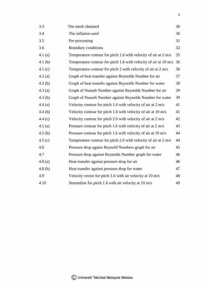
x
3.3 The mesh obtained 30
3.4 The inflation used 30
3.5 Pre processing 31
3.6 Boundary conditions 32
4.1 (a) Temperature contour for pitch 1.6 with velocity of air at 2 m/s 35
4.1 (b) Temperature contour for pitch 1.6 with velocity of air at 10 m/s 36
4.1 (c) Temperature contour for pitch 2 with velocity of air at 2 m/s 36
4.2 (a) Graph of heat transfer against Reynolds Number for air 37
4.2 (b) Graph of heat transfer against Reynolds Number for water 38
4.3 (a) Graph of Nusselt Number against Reynolds Number for air 39
4.3 (b) Graph of Nusselt Number against Reynolds Number for water 39
4.4 (a) Velocity contour for pitch 1.6 with velocity of air at 2 m/s 41
4.4 (b) Velocity contour for pitch 1.6 with velocity of air at 10 m/s 41
4.4 (c) Velocity contour for pitch 2.0 with velocity of air at 2 m/s 42
4.5 (a) Pressure contour for pitch 1.6 with velocity of air at 2 m/s 43
4.5 (b) Pressure contour for pitch 1.6 with velocity of air at 10 m/s 44
4.5 (c) Temperature contour for pitch 2.0 with velocity of air at 2 m/s 44
4.6 Pressure drop agains Reynold Numbers graph for air 45
4.7 Pressure drop against Reynolds Number graph for water 46
4.8 (a) Heat transfer against pressure drop for air 46
4.8 (b) Heat transfer against pressure drop for water 47
4.9 Velocity vector for pitch 1.6 with air velocity at 10 m/s 48
4.10 Streamline for pitch 1.6 with air velocity at 10 m/s 49
xi
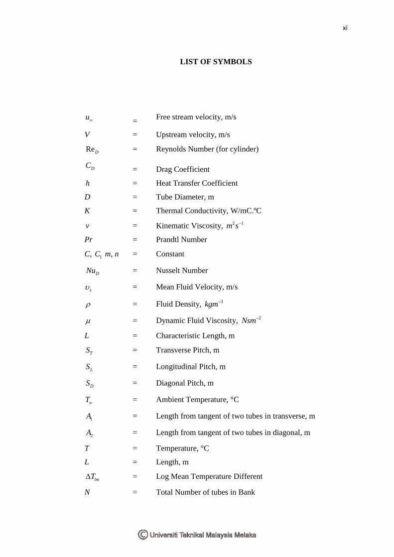
LIST OF SYMBOLS
u = Free stream velocity, m/s
V = Upstream velocity, m/s
ReD = Reynolds Number (for cylinder)
DC = Drag Coefficient
h = Heat Transfer Coefficient
D = Tube Diameter, m
K = Thermal Conductivity, W/mC.ºC
v = Kinematic Viscosity, 2 1m s
Pr = Prandtl Number
C, 1C m, n = Constant
DNu = Nusselt Number
s = Mean Fluid Velocity, m/s
= Fluid Density, 3kgm
= Dynamic Fluid Viscosity, 2Nsm
L = Characteristic Length, m
TS = Transverse Pitch, m
LS = Longitudinal Pitch, m
DS = Diagonal Pitch, m
T = Ambient Temperature, °C
1A = Length from tangent of two tubes in transverse, m
2A = Length from tangent of two tubes in diagonal, m
T = Temperature, °C
L = Length, m
lmT = Log Mean Temperature Different
N = Total Number of tubes in Bank
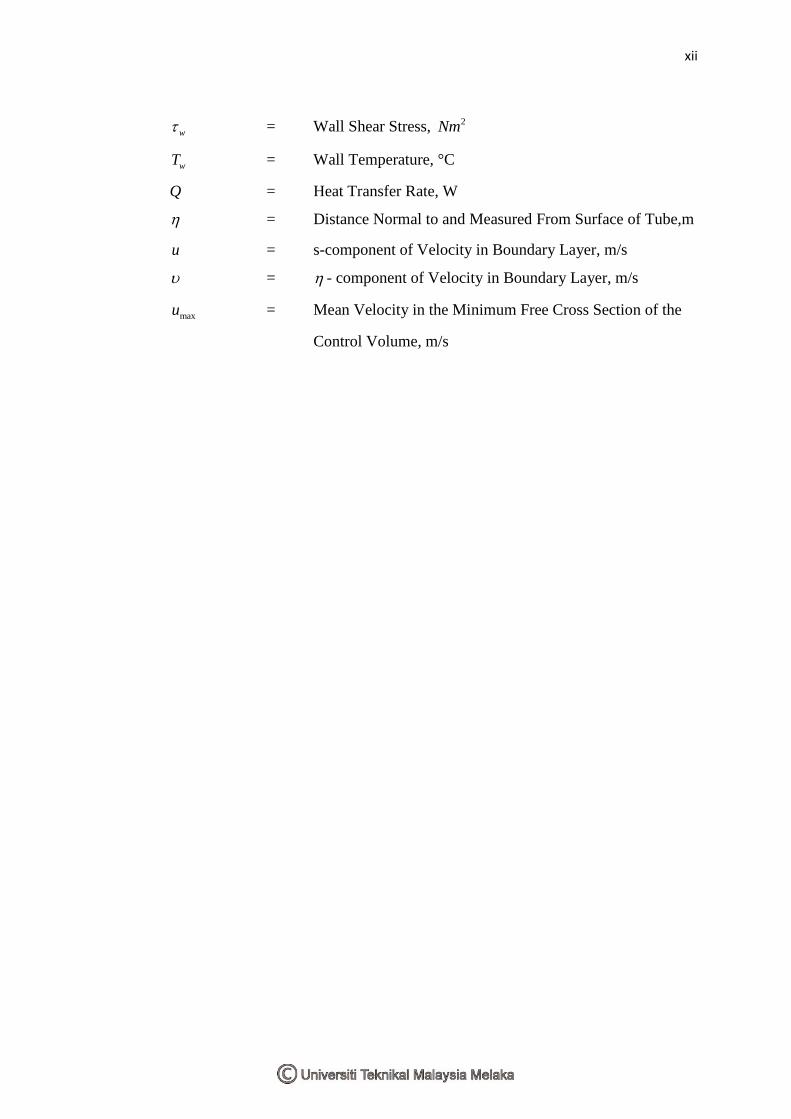
xii
w = Wall Shear Stress, 2Nm
wT = Wall Temperature, °C
Q = Heat Transfer Rate, W
= Distance Normal to and Measured From Surface of Tube,m
u = s-component of Velocity in Boundary Layer, m/s
= - component of Velocity in Boundary Layer, m/s
maxu = Mean Velocity in the Minimum Free Cross Section of the
Control Volume, m/s
xiii
LIST OF ABBREVATIONS
CFD = Computational Fluid Dynamic
REV = Representative Elementary Volume
RSM = Reynolds Stress Model
RMS = Root Mean Square
2D = Two Dimension
3D = Three Dimension
CAD = Computer Aided Design
FEM = Finite Element Method
DNS = Direct Numerical Simulation
LES = Large Eddy Simulation
1
CHAPTER I
INTRODUCTION
This chapter will explained briefly about predicting turbulent in a staggered
tube using computational fluid dynamic, the objective of this study, scopes and the
problem statements.
1.1 Predicting Turbulent in a Staggered Tube
The earliest numerical solution in studying steady flow across a circular
cylinder was reported during 1933. Since that early work, many studies of flow and
heat transfer across tubes and within tube banks have been done using CFD
(Computational Fluid Dynamic) software. Heat transfer and flow characteristic
prediction across cylinder are important in various engineering aspect and have been
presented in many related engineering application. This have been an active research
because it have many benefits in practical of heat exchanger tube bundles, flow
across overhead cables and for nuclear power plant cooling system.
To obtain the flow characteristic and heat transfer around tube bundles,
Navier Stokes and Energy equation can be used to calculate them. Better degree of
approximation can be obtain depending on many factors including the solution
method, mesh size, boundary condition and the stability and convergence criteria.
Although there are many experiment and data that had been done and collected by
previous researchers, it is yet possible to get a clear view about the flow and heat
transfer process across tube bundles because of its complex geometry and there are
many large number of parameter involved.
In this study, CFD software will also be used to predict the heat transfer and
turbulent flow across staggered tubes. CFD simulation for turbulence is harder to
2
make rather than laminar flow because the turbulence flow field are always unsteady
(random, swirling, vertical structures called turbulence eddies). There are many ways
to solve the CFD calculation such as Finite Element Method, Direct Numerical
Simulation and Large Eddy Simulation. Finite Element Method will be used for the
CFD calculation in this study because the CFD software chooses are based on the
FEM.
1.2 Objective
The objectives of this study are to predict the heat transfer and flow
distribution of a staggered tube.
1.3 Scopes
Design CFD staggered tube geometry.
Simulate air and water through an array of heated staggered tube.
1.4 Problem Statement
To simulate a flow across staggered tube, many parameters have to be
decided. These parameters will affect the simulation results. There several
parameters that must be considered for predicting turbulent in a staggered tube which
are:
Longitudinal and transverse pitch
Reynolds Number
Thermal and wall boundary condition
Surface Roughness (in this study it is consider a smooth tube)
3
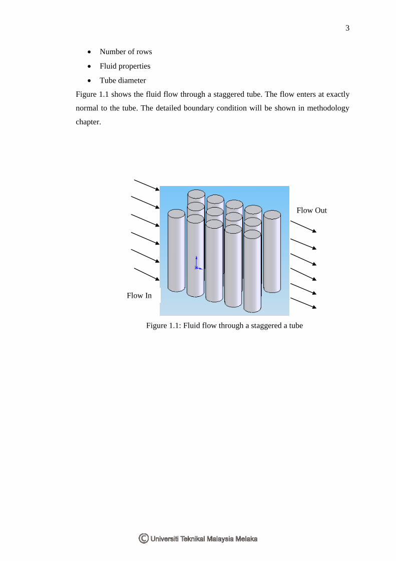
Number of rows
Fluid properties
Tube diameter
Figure 1.1 shows the fluid flow through a staggered tube. The flow enters at exactly
normal to the tube. The detailed boundary condition will be shown in methodology
chapter.
Figure 1.1: Fluid flow through a staggered a tube
Flow In
Flow Out
4
CHAPTER II
LITERATURE REVIEW
This chapter will explain in detail about the flow across cylinder and tube
bank and the formula used. It also includes the previous studies that have been done
by previous researchers.
2.1 Introduction
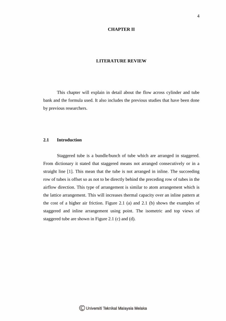
Staggered tube is a bundle/bunch of tube which are arranged in staggered.
From dictionary it stated that staggered means not arranged consecutively or in a
straight line [1]. This mean that the tube is not arranged in inline. The succeeding
row of tubes is offset so as not to be directly behind the preceding row of tubes in the
airflow direction. This type of arrangement is similar to atom arrangement which is
the lattice arrangement. This will increases thermal capacity over an inline pattern at
the cost of a higher air friction. Figure 2.1 (a) and 2.1 (b) shows the examples of
staggered and inline arrangement using point. The isometric and top views of
staggered tube are shown in Figure 2.1 (c) and (d).
5
(a) (b)
(c) (d)
Figure 2.1: Shows the points that are arranged in staggered (a) and inline (a)
while (c) and (d) shows the isometric view and top view of a
staggered tube
Staggered tube is important in many industrial applications. As mentioned in
the introduction chapter, it can be used in nuclear power plant, steam generation in a
boiler and coil of an air conditioner. Many studies have been done because of its
potential and importance in heat exchanger. In this study the staggered tube bank will
be study numerically using CFD package software Ansys CFX.
2.2 Computational Fluid Dynamic
CFD is a computational technology that enables you to study the dynamics of
things that flow [2]. CFD is one of the branches of fluid mechanic that uses
numerical method and algorithm to solve problems that interconnect with fluid flow
[3]. With CFD people can build a virtual model that represents the system and device
that he/she wants to study. Then fluid flow physic and chemistry can be applied to it
and computers will perform the millions of calculation that required in the simulation
[2].
6
2.3 Flows across Cylinder
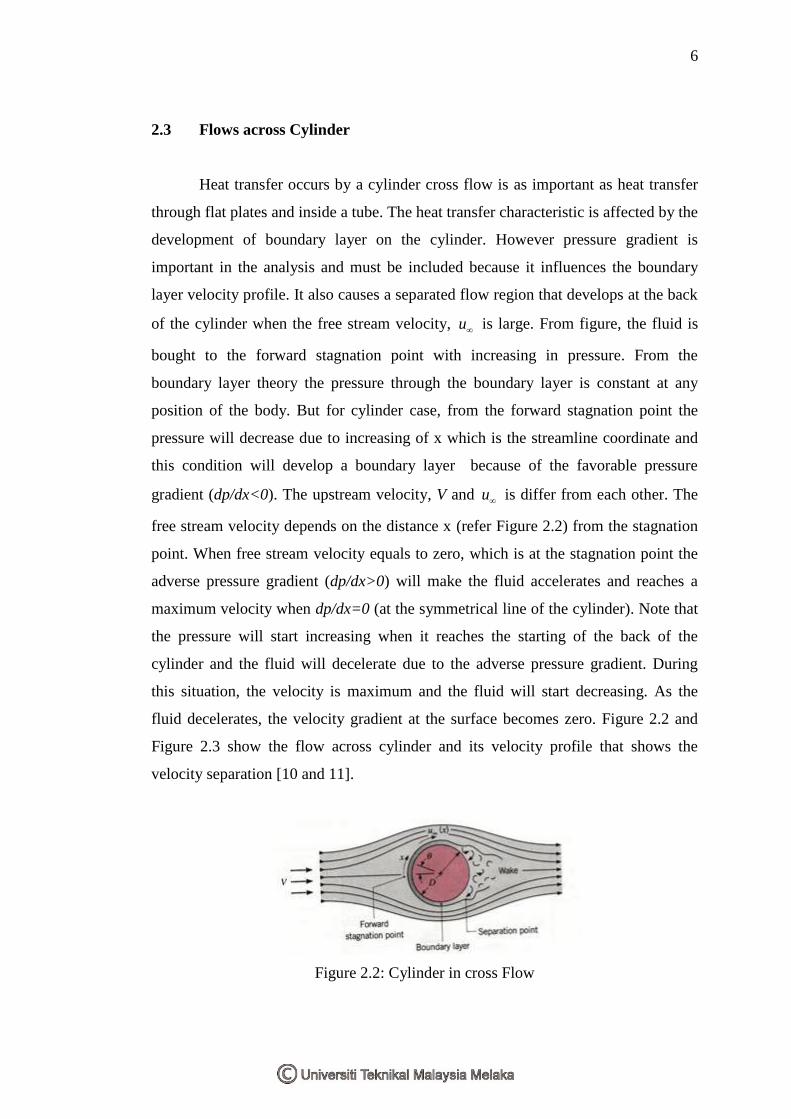
Heat transfer occurs by a cylinder cross flow is as important as heat transfer
through flat plates and inside a tube. The heat transfer characteristic is affected by the
development of boundary layer on the cylinder. However pressure gradient is
important in the analysis and must be included because it influences the boundary
layer velocity profile. It also causes a separated flow region that develops at the back
of the cylinder when the free stream velocity, u is large. From figure, the fluid is
bought to the forward stagnation point with increasing in pressure. From the
boundary layer theory the pressure through the boundary layer is constant at any
position of the body. But for cylinder case, from the forward stagnation point the
pressure will decrease due to increasing of x which is the streamline coordinate and
this condition will develop a boundary layer because of the favorable pressure
gradient (dp/dx<0). The upstream velocity, V and u is differ from each other. The
free stream velocity depends on the distance x (refer Figure 2.2) from the stagnation
point. When free stream velocity equals to zero, which is at the stagnation point the
adverse pressure gradient (dp/dx>0) will make the fluid accelerates and reaches a
maximum velocity when dp/dx=0 (at the symmetrical line of the cylinder). Note that
the pressure will start increasing when it reaches the starting of the back of the
cylinder and the fluid will decelerate due to the adverse pressure gradient. During
this situation, the velocity is maximum and the fluid will start decreasing. As the
fluid decelerates, the velocity gradient at the surface becomes zero. Figure 2.2 and
Figure 2.3 show the flow across cylinder and its velocity profile that shows the
velocity separation [10 and 11].
Figure 2.2: Cylinder in cross Flow
7
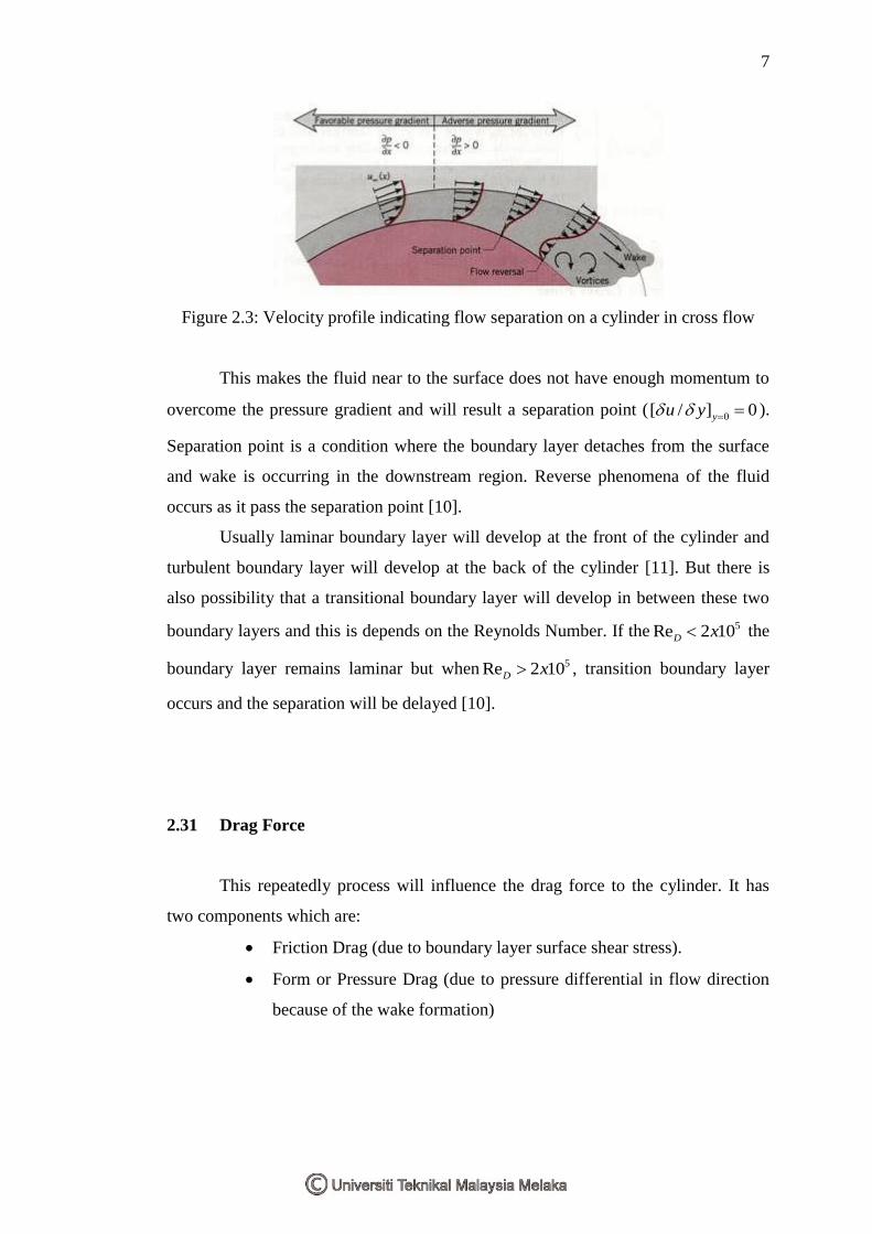
Figure 2.3: Velocity profile indicating flow separation on a cylinder in cross flow
This makes the fluid near to the surface does not have enough momentum to
overcome the pressure gradient and will result a separation point (0[ / ] 0yu y ).
Separation point is a condition where the boundary layer detaches from the surface
and wake is occurring in the downstream region. Reverse phenomena of the fluid
occurs as it pass the separation point [10].
Usually laminar boundary layer will develop at the front of the cylinder and
turbulent boundary layer will develop at the back of the cylinder [11]. But there is
also possibility that a transitional boundary layer will develop in between these two
boundary layers and this is depends on the Reynolds Number. If the 5Re 2 10D x the
boundary layer remains laminar but when 5Re 2 10D x , transition boundary layer
occurs and the separation will be delayed [10].
2.31 Drag Force
This repeatedly process will influence the drag force to the cylinder. It has
two components which are:
Friction Drag (due to boundary layer surface shear stress).
Form or Pressure Drag (due to pressure differential in flow direction
because of the wake formation)
8
A drag coefficient can be defined as:
2( / 2)
DD
f
FC
A V
(2.1)
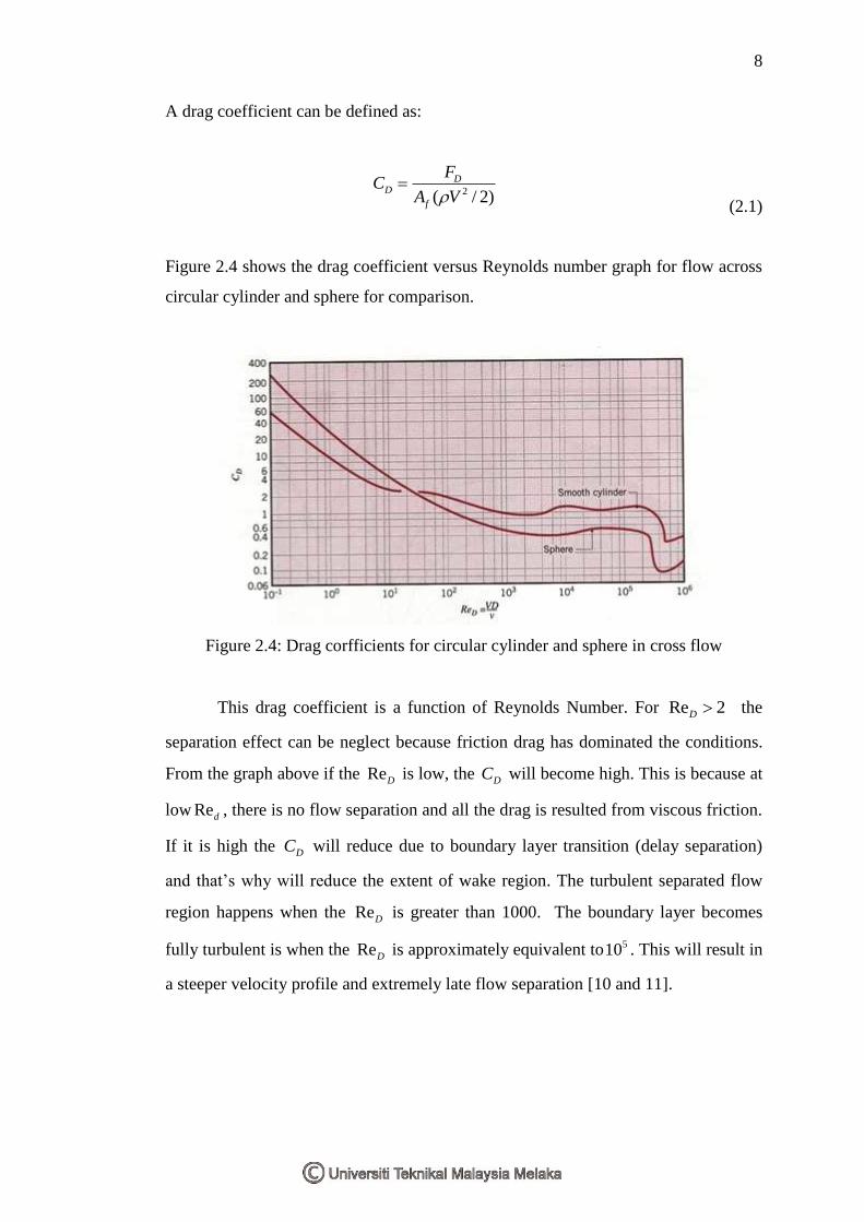
Figure 2.4 shows the drag coefficient versus Reynolds number graph for flow across
circular cylinder and sphere for comparison.
Figure 2.4: Drag corfficients for circular cylinder and sphere in cross flow
This drag coefficient is a function of Reynolds Number. For Re 2D the
separation effect can be neglect because friction drag has dominated the conditions.
From the graph above if the ReD is low, the DC will become high. This is because at
low Red , there is no flow separation and all the drag is resulted from viscous friction.
If it is high the DC will reduce due to boundary layer transition (delay separation)
and that’s why will reduce the extent of wake region. The turbulent separated flow
region happens when the ReD is greater than 1000. The boundary layer becomes
fully turbulent is when the ReD is approximately equivalent to 510 . This will result in
a steeper velocity profile and extremely late flow separation [10 and 11].
9
2.32 Correlation for Average Heat Transfer
There are actually 3 correlation equations for average heat transfer of flow across
cylinder. The equations are stated below.
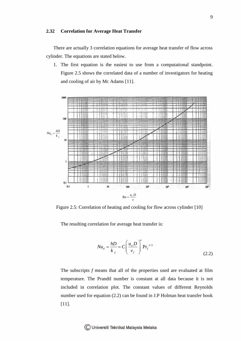
1. The first equation is the easiest to use from a computational standpoint.
Figure 2.5 shows the correlated data of a number of investigators for heating
and cooling of air by Mc Adams [11].
d
f
hDNu
k
Reu D
v
Figure 2.5: Correlation of heating and cooling for flow across cylinder [10]
The resulting correlation for average heat transfer is:
1/3Pr
n
d f
f f
u DhDNu C
k v
(2.2)
The subscripts f means that all of the properties used are evaluated at film
temperature. The Prandtl number is constant at all data because it is not
included in correlation plot. The constant values of different Reynolds
number used for equation (2.2) can be found in J.P Holman heat transfer book
[11].