perpustakaan uthm iii~m~iiii~~ · untuk menganalisa secara komprehensif. projek ini menggunakan...
TRANSCRIPT

PERPUSTAKAAN UTHM I '_
IIIWWWWW~m~IIII~~ *30000001883375*
KOLEJ UNIVERSITI TEKNOLOGI TUN HUSSEIN ONN
BORANG PENGESAHAN STATUS TESIS·
JUDUL: An improvement to intergated model of electro pneumatic circuit for material handling in a manufacturing cell
SESI PENGAJIAN: 2004/2005
Saya MOHAMAD NORANI BIN MANSOR (HURUF BESAR)
mengaku membenarkan tesis (Sarjana MudalSarjana !Doktor Falsaf.'lh)* ini disimpan di Perpustakaan dengan syarat-syarat kegunaan seperti berikut:
I. Tesis adalah hakmilik Kolej Universiti Teknologi Tun Hussein Onn. 2. Perpustakaan dibenarkan membuat salinan untuk tujuan pengajian sahaja. 3. Perpustakaan dibenarkan membuat salinan tesis ini sebagai bahan pertukaran antara institusi
pengajian tinggi. 4. "Sila tandakan (..J )
SULIT
TERHAD
(Mengandungi maklumat yang berdaljah keselamalan at au kepentingan Malaysia seperti yang termaktub di dalam AKTA RAHSIA RASMI1972)
(Mengandungi maklumat TERHAD yang telah ditentukan oleh organisasilbadan di mana penyelidikan dijalankan)
..J TIDAK TERHAD
(TANDATANGAN PENULlS)
Alamat Tetap:
NO.6, JALAN MELATI, P.M. DR. H.I. SULAIMAN BIN H.I. HASAN (Nama Penyelia ) TAMAN MAJU BARU, PARIT RAJA
86400 BATU PAHAT,JOHOR
Tarikh: 04 - 04 - 2005 Tarikh: 04 - 04 - 2005
CATATAN: **
Po tong yang tidak berkenaan. Jib tesis ini SULIT atau TERHAD, sila lampirkan sural daripada pihak berkuasalorganisasi berkenaan dengan menyatakan sekali tempoh tesis ini perlu dikelaskan sebagai atau TERHAD. Tesis dimaksudkan sebagai tesis bagi ljazah dok1or Falsafah dan Sarjana secara Penyelidikan, alau disertasi bagi pengajian secara kerja kursus dan penyelidikan, atau Laporan Projek Sarjana Muda (PSM).
"I hereby declare that 1 have read this thesis and in my opinion this thesis
is sufficient in terms of scope and quality for the award of the degree of Master of
Engineering"
Signature
Name of supervisor
Date 04 -04 -2005
11
An improvement to integrated model of electro pneumatic circuit for
material handling in a manufacturing cell
Presented in Partial Fulfillment of the Requirement for
the Master in Mechanical Engineering in the Graduate School
of Kolej Universiti Teknologi Tun Hussein Onn
By
Mohamad Norani Bin Mansor
Kolej Universiti Teknologi Tun Hussein Onn
2005
III
"I declare that this thesis entitled 'An improvement to integrated model
of electro pneumatic circuit for material handling in a manufacturing cell' is
the result of my own research except as cited in the references. The thesis has not
been accepted for any degree and is not concurrently submitted in candidature of
any other degree"
Signature
Name of candidate MOHAMAD NORAN1 BIN MANSOR
Date 04 - 04 -2005
IV
v
DEDICATION
To:
All Mllslimin and Mllslimat
ACHKNOWLEDGEMENT
I would like to express my deepest gratitude and appreciation to my academic
advisor Associate Prof. Dr. Sulaiman Bin Haji Hasan for his ideas, throughout and for his
guidance in my project. I wish to thank Associate Prof. Dr. Ir. Saparudin Bin Haji Ariffin
for his willingness to provide me with his helpful suggestion and comments.
I am also grateful to Mr. Abdul Rahman Iskandar Bin Abdul lawat, Mr.
Sharifunazri Bin lohadi, Mr. Mohd Isa Bin Rosdi and Mr. Ramlee Bin Hussin who have
shared their working experience and knowledge has assisted me carrying out the
experiments in Automation Laboratory. Thanks also to my colleagues in Department of
Manufacturing Engineering and Industry for their commitments.
Finally, I would like to thank my parents, family, all my former lecturers and
friends. None of this work would not have been possible without their sacrifices and
encouragements.
VI
Abstract
Pneumatic circuit are very widely used in automating plants especially
manufacturing plants. These circuits are implemented for material handling,
process control and general automation. Selecting an effective design,
components and appropriate system will be a critical item in installing an
effective and efficient system. One sure way of acquiring this is the application of
software especially those that have comprehensive analytical capability. In this
project the author used Automation Studio to study the effect of adding extra
component and valve to a three cylinder integrated material handling system. The
evaluation has shown that adding components have shown some positive effect on
the system. However some components provide advantages some do not.
Automation Studio has prove to be an effective tool to determine this.
Vll
Abstrak
Penggunaan sistem pneumatik sangat banyak digunakan dalam loji
automatik terutamanya dalam sektor pembuatan. Ianya banyak diguna pakai untuk
pengangkutan barangan, proses kawalan dan kegunaan automasi. Pemilihan untuk
rekabentuk yang berkesan, komponen dan sistem yang baik adalah perkara yang
kritikal ketika pemasangan hendak dilakukan untuk kecekapan sistem tersebut.
Suatu penyelesaiannya ialah dengan menggunakan 'software' yang berkebolehan
untuk menganalisa secara komprehensif. Projek ini menggunakan 'Automation
studio' untuk menganalisa kesan terhadap penambahan komponen dan injap pad a
tiga selinder dalam sistem rangkaian pengangkutan barangan. Dapatan yang
diperolehi menunjukan bahawa dengan menambah komponen dan injap telah
mendatangkan kesan kepada sistem tersebut. Walaubagaimanapun, ada komponen
dan injap yang dipasang itu mendatangkan kebaikan dan ada yang tidak.
Penggunaan 'Automation studio' ini menunjukan salah satu kaedah yang sangat
berkesan dalam kajian projek ini.
Vlll
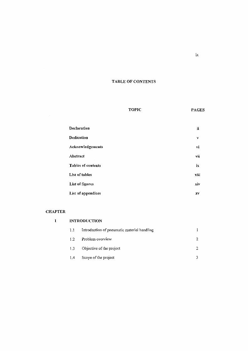
TABLE OF CONTENTS
TOPIC
Declaration
Dedication
Acknowledgements
Abstract
Tables of contents
List of tables
List of figures
List of appendices
CHAPTER
I INTRODUCTION
1.1 Introduction of pneumatic material handling
1.2
1.3
1.4
Problem overview
Objective of the project
Scope of the project
IX
PAGES
ii
v
vi
vii
ix
xiii
xiv
xv
2
2
3
II
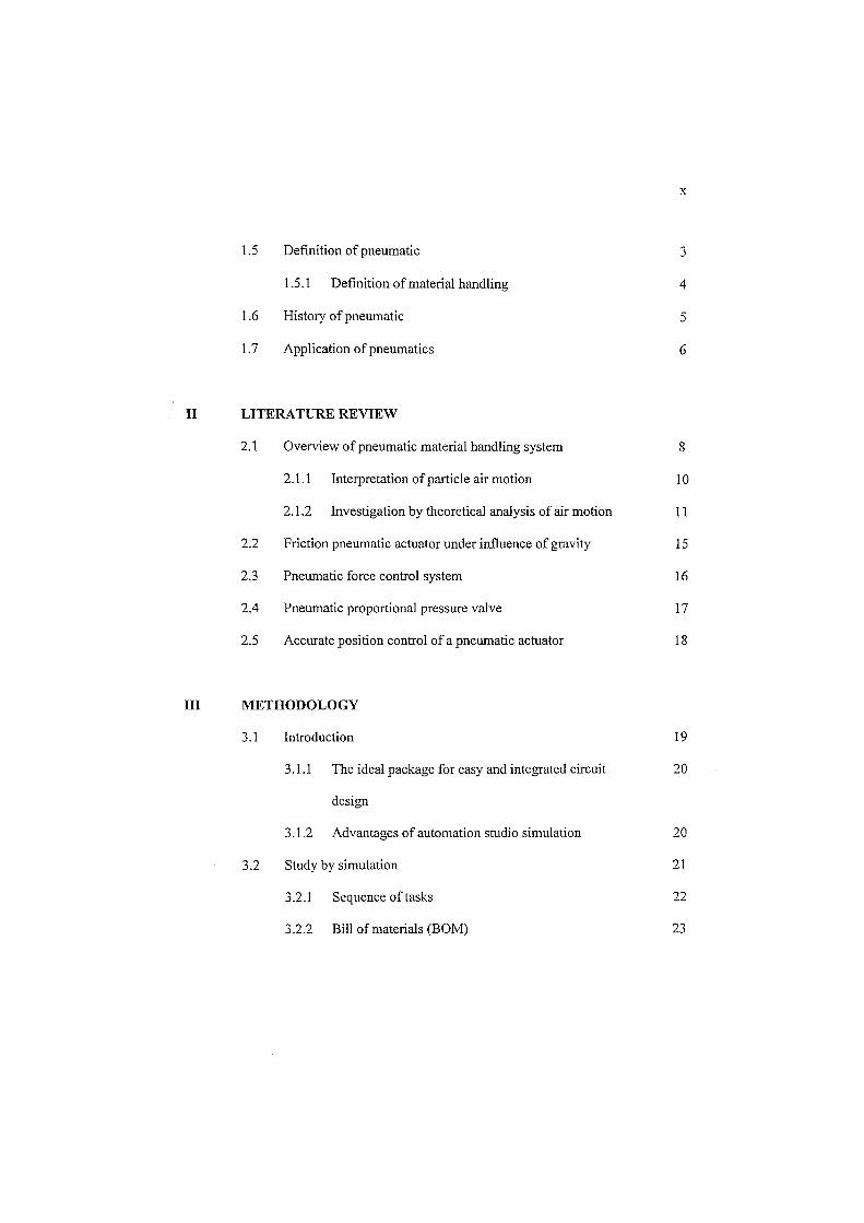
1.5
1.6
1.7
Definition of pneumatic
1.5.1 Definition of material handling
History of pneumatic
Application of pneumatics
LITERATURE REVIEW
2.1 Overview of pneumatic material handling system
2.1.1 Interpretation of particle air motion
2.1.2 Investigation by theoretical analysis of air motion
2.2 Friction pneumatic actuator under influence of gravity
2.3 Pneumatic force control system
2.4 Pneumatic proportional pressure valve
2.5 Accurate position control of a pneumatic actuator
III METHODOLOGY
3.1 Introduction
3.1.1 The ideal package for easy and integrated circuit
design
3.1.2 Advantages of automation studio simulation
3.2 Study by simulation
3.2.1 Sequence of tasks
3.2.2 Bill of materials (BOM)
x
3
4
5
6
8
10
11
15
16
17
18
19
20
20
21
22
23
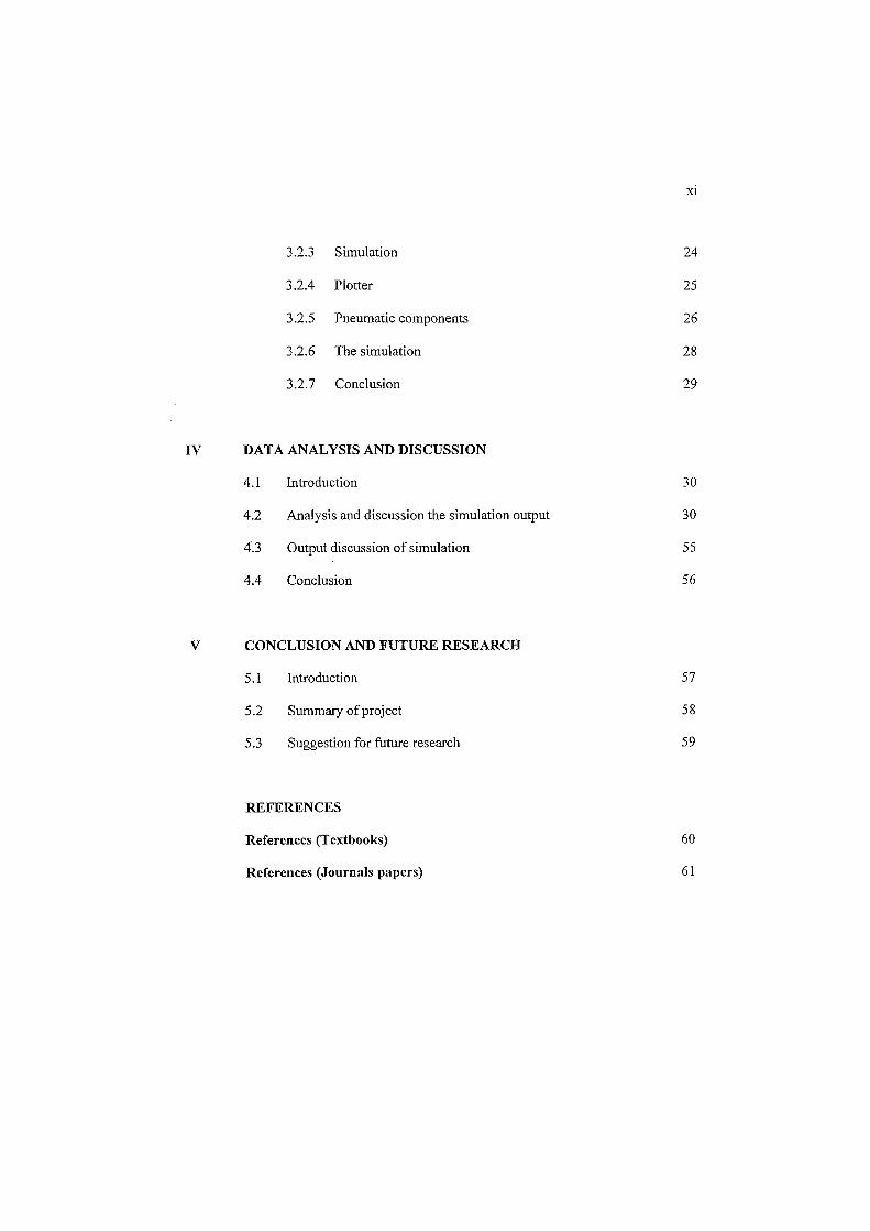
3.2.3 Simulation
3.2.4 Plotter
3.2.5 Pneumatic components
3.2.6 The simulation
3.2.7 Conclusion
IV DATA ANALYSIS AND DISCUSSION
4.1 Introduction
4.2 Analysis and discussion the simulation output
4.3 Output discussion of simulation
4.4 Conclusion
V CONCLUSION AND FUTURE RESEARCH
5.1
5.2
5.3
Introduction
Summary of project
Suggestion for future research
REFERENCES
References (Textbooks)
References (Journals papers)
Xl
24
25
26
28
29
30
30
55
56
57
58
59
60
61
Xli
GLOSSARY
List of glossary 63
APPENDICES
Appendix A Flow chart activity planning for master project 65
Appendix B Gantt chart for master project 67
Appendix C Others related document 69
Xlll
List of tables
Table Descriptions Page
Table 1.1 Historical development of mechanical, electrical and electronics system 6
Table 2.1 Properties of pneumatics material handling system 9
Table 3.1 The components list of pneumatic simulation 24
Table 4.1 Result of simulation 55
XIV
List of figures
Figure Descriptions Page
Fig. 2.1 Pneumatic material handling system 8
Fig. 2.2 Particle trajectories in a channel flow (channel height 35 mm and length 6 m) 10
Without wall roughness: a) 30 flm and b) 110 flm
With wall roughness : c) 30 flm and d) 110 flm
Fig. 3.1 Schematic pneumatic material handling system 21
Fig. 3.2 Tasks sequence 22
Fig. 3.3 Circuit of pneumatic material handling system 23
Fig. 4.1 Horizontal pneumatic cylinder 33
Fig. 4.2 Initial condition of pneumatic circuit 34
Fig. 4.3 Throttle valve (first cylinder) 35
Fig. 4.4 Pressure regulator (first cylinder) 36
Fig. 4.5 Pressure relief valve (first cylinder) 37
Fig. 4.6 Counterbalance valve (first cylinder) 38
Fig. 4.7 Combination pressure regulator and throttle (first cylinder) 39
Fig. 4.8 Throttle valve (three cylinder) 40
Fig. 4.9 Pressure regulator (three cylinder) 43
Fig. 4.10 Pressure relief valve (three cylinder) 46
Fig. 4.11 Counterbalance valve (three cylinder) 49
Fig. 4.12 Combination pressure regulator and throttle (three cylinder) 52
List of appendices
Appendix Descriptions
A Flow chart activity planning for master project
B Gantt chart for master project
C Others related documents
xv
Page
65
67
69
CHAPTER I
Introduction
1.1 Introduction of pneumatic material handling
Pneumatic technology is very important in automation. This is especially
important in manufacturing industries. Pneumatics like hydraulic in an industry is
used to move material, control movement and assist in automatic process and
operation. Thus pneumatic is an important source of power in material handling.
Certain characteristics of compressed air have made this medium quite suitable
for use in modem manufacturing and production plants.
As a key component of manufacturing systems, material handling interacts
with the facility layout and system control or scheduling problems. The material
handling system requires the logical and physical aspects of material flow and
equipment to justified from both performance and economic perspectives.
The work takes into account the various of material handling operations
that take place during manufacturing like the processing machines, equipments
and character of the part types. It is an integrating of operation allocation problem
and the considerations of material handling systems.
1.2 Problem overview
Pneumatics is low cost alternative to material handling tasks in term of
support and service available in the manufacturing system. The potential of this
drive medium is now recognized, particularly for linear motion application.
However, a number of problem and challenges still remain for it to realize for
industrial control motion.
Pneumatic cylinder in an integrated form can perform a lot of task and
assist engineer in operation. However normally it is difficult to ensure
optimization because one need the right combination of valve, control and circuit
to obtain optimization. This research will observe one aspect of the optimization
or improvement of a pneumatic system. Three cylinder controlled by an additional
valve may smoother the operation or may hinder an efficient system. This project
will focus on one aspect of this improvement.
1.3 Objective of the project
1. To study the effect of additional component on a three cylinder integrated
pneumatic system for material handling.
2. To compare performance of the above system and suggest the best
combination.
3. To identify the best additional component for the system.
2
1.4 Scope of the project
Below are the scopes of the project:
1. The project will be focused on three cylinder material handling pneumatic
system.
2. The project will also be limited to five types of additional valves or
components added to the system and also the circuit selected are not modified
throughout the experiment.
1.5 Definition of pneumatic
"The English word pneumatic and its associate noun pneumatics are
derived from the Greek pneuma meaning 'breath'. Originally coined to give a
name to the science of the motions and properties of air, pneumatics has been
adopted by engineers to identify the branch of physics treating of the mechanical
properties of air and other gases, now used somewhat more restrictedly to refer to
the phase of fluid mechanics dealing with the properties, actions and applications
of gases, but chiefly air, at pressures higher or lower than atmospheric".
(Werner Deppet alld Kurt Stoll, 1975: 7)
The technology of pneumatics deals with the behavior and application of
compressed air. The science of air was known and used in industry before the
beginning of the Second World War (1939-44). During the war, many industries
like western countries started switching more automatic equipment and
machineries. Many of these were operated by pneumatically and use in
manufacturing and other activities. This was the present the concept of pneumatic
material handling system to use compressed air in production plants.
3
1.5.1 Definition of material handling
Materials handling involves the loading, moving and unloading of
materials. The loading, moving and unloading of ore from a mine to a mill and of
garments within a factory are examples of materials handling. There are hundreds
of different ways of handling materials. These are generally classified according
to the type of equipment used. For example, the International Materials
Management Society has classified equipment as (I) conveyor; (2) cranes,
elevators and hoists; (3) positioning, weighing and control equipment; (4)
industrial vehicles; (5) motor vehicles; (6) railroad cars; (7) marine carriers; (8)
aircraft and (9) containers and supports.
Every materials handling problem starts with the material - its dimensions,
its nature and its characteristics. Engineers who fail to start here usually end up
trying to justify equipment rather than achieving safe and economical movement
of the material. The quantity to be moved both in total and in rate of moving
desired is next in selecting the appropriate handling method. Then comes the
sequence of operations or the routing. Basically, this what, when (how much and
how often) and where is the minimum information needed to evaluate or
determine any handling system or equipment.
Materials handling is both a planning and an operating activity. These two
activities are generally separated in industry, an analytical group designs or
selects the system or equipment and the operating group puts it to use.
(Mel Schwartz, 2002: Second Edition)
4
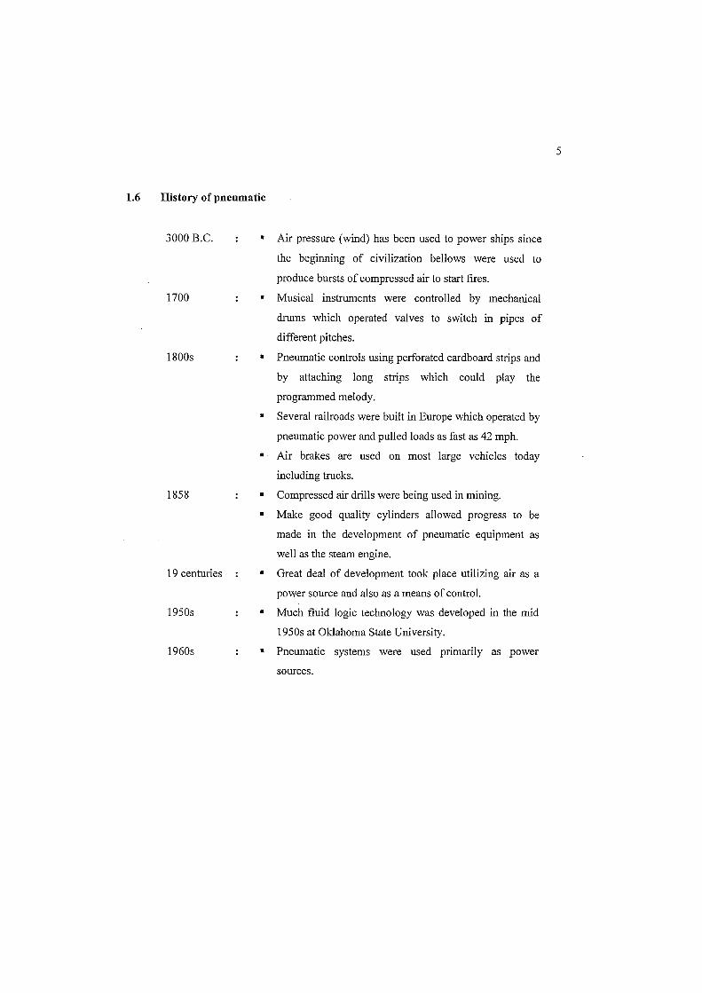
1.6 History of pneumatic
3000 B.C.
1700
1800s
1858
19 centuries
1950s
1960s
• Air pressure (wind) has been used to power ships since
the beginning of civilization bellows were used to
produce bursts of compressed air to start fIres.
• Musical instruments were controlled by mechanical
drums which operated valves to switch in pipes of
different pitches.
• Pneumatic controls using perforated cardboard strips and
by attaching long strips which could play the
programmed melody.
• Several railroads were built in Europe which operated by
pneumatic power and pulled loads as fast as 42 mph.
• Air brakes are used on most large vehicles today
including trucks.
• Compressed air drills were being used in mining.
• Make good quality cylinders allowed progress to be
made in the development of pneumatic equipment as
well as the steam engine.
• Great deal of development took place utilizing air as a
power source and also as a means of contro!'
• Much fluid logic technology was developed in the mid
1950s at Oklahoma State University.
• Pneumatic systems were used primarily as power
sources.
5
1. 7 Application of pneumatics
With the introduction of pneumatics in the manufacturing process, the
industry is benefited with a cheaper medium of material handling which easy to
used and bring down the cost of production to a much lower level. Therefore,
today air operated tools and accessories are a common in industry.
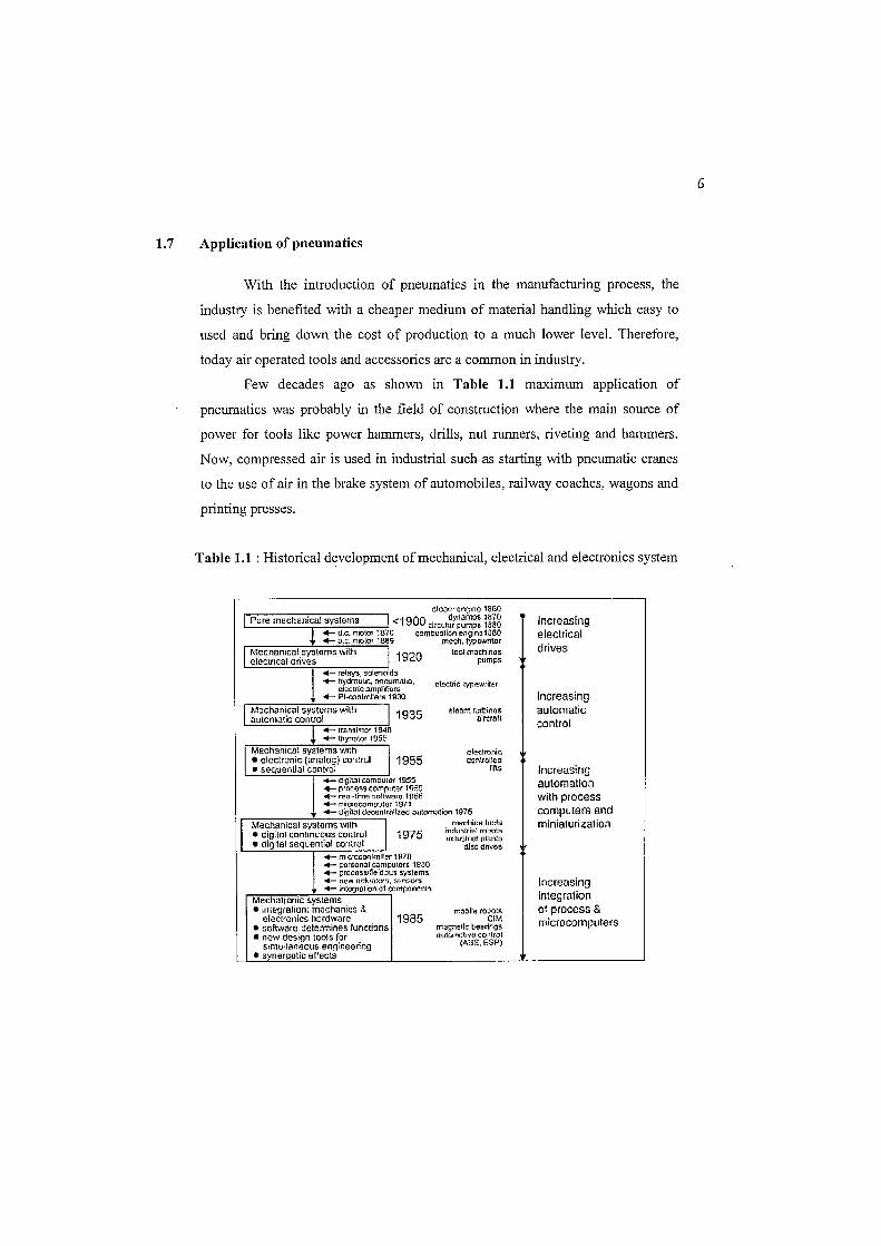
Few decades ago as shown in Table 1.1 maximum application of
pneumatics was probably in the field of construction where the main source of
power for tools like power hammers, drills, nut runners, riveting and hammers.
Now, compressed air is used in industrial such as starting with pneumatic cranes
to the use of air in the brake system of automobiles, railway coaches, wagons and
printing presses.
Table 1.1 : Historical development of mechanical, electrical and electronics system
G-!cam cn[poo 1660 Pure mechanical """terns 1<1900 d)'namo& 1870 Increasing e!lculnr pump. 1880 ! ...- d.c. moior 1870 O!:Imbustlcn en.glna1S80 electrical
-+- o.c. molO! 1689 mecl1. typewritor drives Mechanical """Iems wilh 1920 teol machInes
eleclrical drives pumps ~ relays, solenQids +- hydmurJC, rof!.oum~'\tt~, electric typewriter e1Elctnc amplifiers +- PI<onlroU.m 1930 Increasing
Mcch~nic~1 systems wilh 1935 ~tC:lm. turbl.no& automatic autom~tic control .Ircraft control +- transistor 1946
+- thy""lor 1955 Mechanical systems wllh
11955
alooronic • eleclronic (analog) control con~ollea
• sequentlnl control lilts Increasing +- digital compul£N 1955 +- proteM computer 1')50 automation ...- reul-time 50nll'rara 1U6B with process ..- microcompulor 1971 -+- dlj]it--'11 decenltnUzed Olutom-ation 1976 computers and
II Mechanical systems wilh
I machine tO~5 miniaturization
• digilsl con~nuous control 1975 indus.lrial rubots rmJustflal pl0l1tO
• digital sequential rontroi dJ!C dnvos .- miacconttoller' 1Q70 .of- pt:lrSonal COmpUI!'l-r& 19ao _ Droce,51fleldbus system, ...- n.t'w ocil1.utcr.;, mJn~..QI11. Increasing -+- int(l!)tOlion 01 cor'rtp.O()t)1)ts
Mechntronic systems integration • integration; mechanics & mobile (Ooot~ of process &
electronics hardwaro 1985 elM microcomputers • software detennines functions rr..agnel[c bea;-Ings • now dosign tools for ilulon'lOtrvu control
simultaneous engineering (1188, ESP)
• synergetic affects
6
The basic features that make application of pneumatics in industries more
advantageous and suitable in material handling system because of the following
features:
1. Wide availability of air.
2. Compressibility of air.
3. Easy transportability of compressed air in pressure vessels, containers and in
long pipes.
4. Fire proof characteristics of the medium.
5. Simple construction of pneumatic elements and easy handling.
6. High degree of controllability of pressure, speed and force.
7. Possibility of easy but reasonably reliable remote controlling.
8. Easier maintenance.
9. Explosion proof characteristics of the medium.
10. Comparatively cheaper in cost than other systems.
Therefore in my opinion, pneumatic system has better operational
advantages and accuracy are concerned in manufacturing system. In areas of
hazards, probably air will be a better medium than the hydraulic system.
7