module 6 handling 20 devices
TRANSCRIPT
KKEEMMEENNTTEERRIIAANN PPEELLAAJJAARRAANN MMAALLAAYYSSIIAA
SSeellff AAcccceessss LLeeaarrnniinngg MMoodduullee
CCoommppuutteerr HHaarrddwwaarree BBaassiicc MMaaiinntteennaannccee
Handling Input and Output Devices
PUSAT PERKEMBANGAN KURIKULUM KEMENTERIAN PELAJARAN MALAYSIA
IIICCCTTT LLLiiittteeerrraaacccyyy fffooorrr SSSeeecccooonnndddaaarrryyy SSSccchhhoooooolll
PPPrrrooogggrrraaammmmmmeee
ICTL for Secondary School - Computer Hardware Module
1
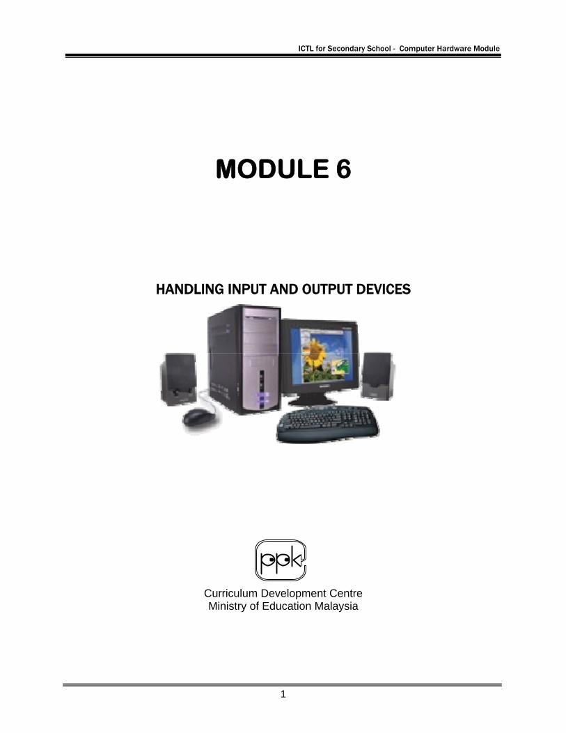
MODULE 6
HANDLING INPUT AND OUTPUT DEVICES
Curriculum Development Centre Ministry of Education Malaysia
ICTL for Secondary School - Computer Hardware Module
2
1. Name of Module : Basic Maintenance – Handling input and output devices 2. Learning Outcomes: The students should be able to:
• to set up the input and output devices correctly
• state the steps to connect the peripherals to system unit
• powering the system
3. Knowledge and Skills
1. Connecting the peripherals 2. Powering the system
4. Module Summary: At the end of the module, students should be able to connect peripherals; monitor, keyboard, mouse and speaker to the system unit
This module contains 5 activities:
Activity 1: Naming the peripheral port on the system unit Activity 2: Connecting the Monitor to the system unit Activity 3: Connecting the Keyboard and mouse to the system unit Activity 4: Connecting the Speaker to the system unit Activity 5: Powering the System
ICTL for Secondary School - Computer Hardware Module
3
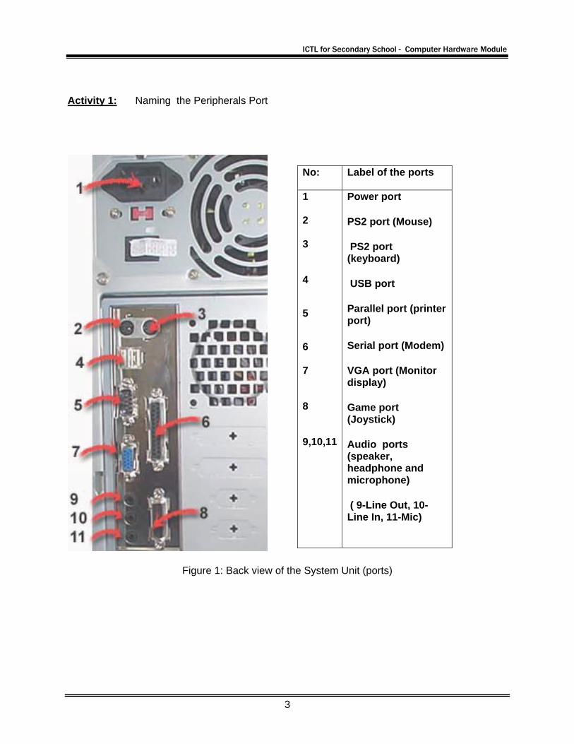
Activity 1: Naming the Peripherals Port
Figure 1: Back view of the System Unit (ports)
No: Label of the ports
1 2 3 4 5 6 7 8 9,10,11
Power port
PS2 port (Mouse)
PS2 port (keyboard)
USB port
Parallel port (printer port)
Serial port (Modem)
VGA port (Monitor display)
Game port (Joystick)
Audio ports (speaker, headphone and microphone)
( 9-Line Out, 10-Line In, 11-Mic)
ICTL for Secondary School - Computer Hardware Module
4
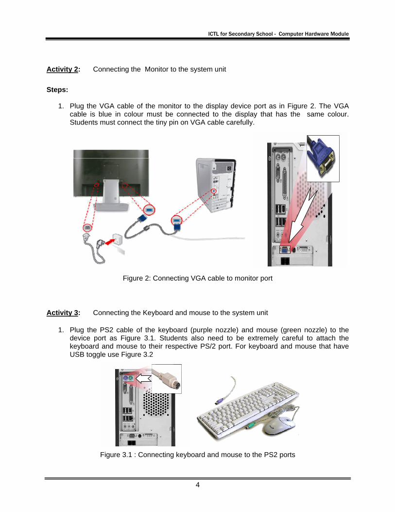
Activity 2: Connecting the Monitor to the system unit
Steps:
1. Plug the VGA cable of the monitor to the display device port as in Figure 2. The VGA cable is blue in colour must be connected to the display that has the same colour. Students must connect the tiny pin on VGA cable carefully.
Figure 2: Connecting VGA cable to monitor port
Activity 3: Connecting the Keyboard and mouse to the system unit
1. Plug the PS2 cable of the keyboard (purple nozzle) and mouse (green nozzle) to the device port as Figure 3.1. Students also need to be extremely careful to attach the keyboard and mouse to their respective PS/2 port. For keyboard and mouse that have USB toggle use Figure 3.2
Figure 3.1 : Connecting keyboard and mouse to the PS2 ports
ICTL for Secondary School - Computer Hardware Module
5
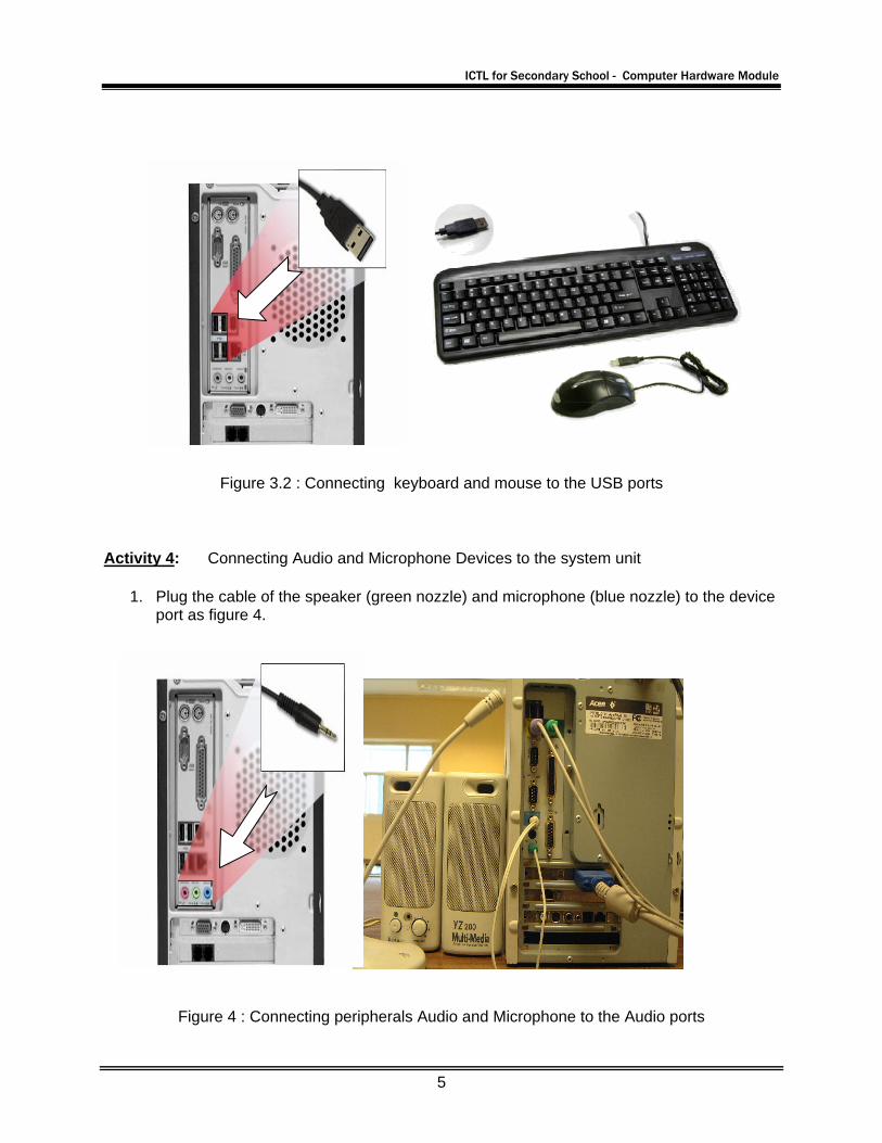
Figure 3.2 : Connecting keyboard and mouse to the USB ports
Activity 4: Connecting Audio and Microphone Devices to the system unit
1. Plug the cable of the speaker (green nozzle) and microphone (blue nozzle) to the device port as figure 4.
Figure 4 : Connecting peripherals Audio and Microphone to the Audio ports
ICTL for Secondary School - Computer Hardware Module
6
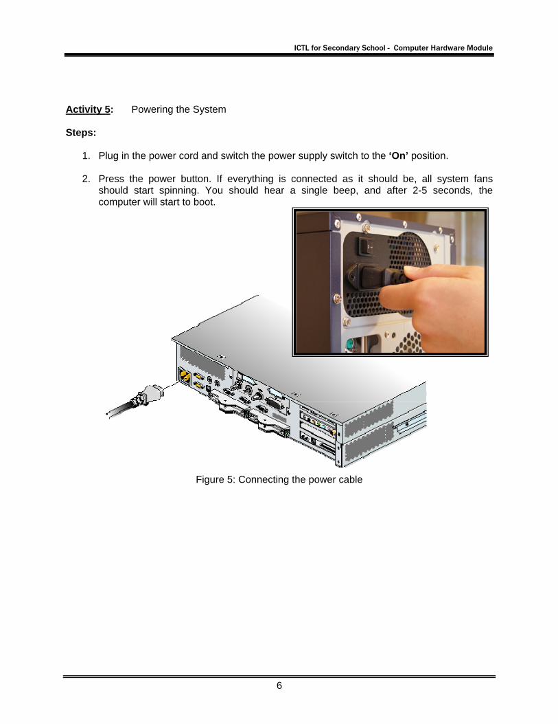
Activity 5: Powering the System Steps:
1. Plug in the power cord and switch the power supply switch to the ‘On’ position.
2. Press the power button. If everything is connected as it should be, all system fans should start spinning. You should hear a single beep, and after 2-5 seconds, the computer will start to boot.
Figure 5: Connecting the power cable