merged document 2
DESCRIPTION
aTRANSCRIPT
rAKI}LTI KE.'I'RUTDRAAN MEI{ANII(AL
UNTIiIERSITI TENIIOLOGI MALAYSIA
PEPERTKSAAN SETWESTER Ir, SESr 2OO7lzo,Ae
KOD KT'RSUS
!{ATT{A KT'RSUS
PROGRAM
TIASA
TARIre
: sMK ,312i3{SZL 3123
: SHIP STRUSHIRE I
: 'SMK/SA.
2 ZYrJAN.
s APRrI,/IIEL 2OO8
ARAIIAN KEPADA CALON JAITAB SEIIUA SOALA}I
alrsurER ArL QrrDsTror{s
ITER:rAS SOALIIN I}II TERDIRI DARIPADA 5 MI'I{ASI'RAT SA}IA.'A
..:
j;:t-,
*ai
(sMK3123)
Question 1
1. The data given below applies to a new frigate design.
{10 ma*s)
1b. calcutrate &e anaximum stressm in the keel and dwk given that $0 marks)
2d momert of areaof wtioa aboutNA : 5.54 ma
total depth
NA above keel
Length
: 10.52 m
- 3.96 m
:110m
ftrestior 2
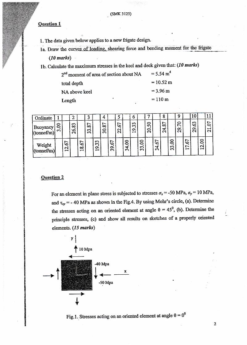
For an elemeat in plane stess is zubjected to stresses 6r: -50 MPa' 6y= 10 MPa,
and r," - - 40 lvlPa as shovm in the Fig.4. By using Mobr's eirclg {a}. Delermine
the s6ses actfurg on a$ oriented ele,ment at angle 0 : 45on {b)- Determine the
principle strsses, (c) and shorn all re$$t$ on sketches of a pmperly oriented
elemenfi.t. $5 lraarl*)
vl
t lor,rpu
<+
j
40Mpa
l.--50Mpa
$
Fig.1. Shesses acting on an oriented element at angle 0:0o2
Ordinate 1 2 5 4 5 6 7 8 9 10 11
Buoyancy(tonneflm)
aqfq
ca@\dC.l
f-oqcnfa
r-coc>crl
r-\oci6l
c.t("]Or
orf-)ool
t-.oo+c.l
ot:Olc'.1
cfi9o\c.l
r-q(\I
Weight(tonneflm)
t-\qol
f-\qooF{
carao\
t-\oOrCA
oq\f,aa
oqcfl(fl
r-\q.<rca
oqc.lca
t-\qtr-
oqc{
. {sMK3123)
Ouestion 3
3a. In {nany cases, ships' plating is subjected to combioed in-plane loads. For
in deck plating both lateral loads-and-ia-planecompressive stress are
present. The application of an in-plane compmive stress wiil magnify the
lateral defl*tion of ir plafe. Descdbe qftat is &e phenomenoa of combind in-
plaue compressive stress on aplate? {5 mar*s}
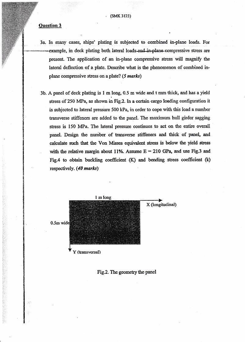
3b. A panel of deck platins is 1 mlong 0,5 m wide and t mrn tbicL and has a yield
sEess df 2S0 MPa" as eholrm in $'ig.2. In a oe*ain sargo loading configuratien it
is subjected to lateral pressure 500 kPa" in order to cope *ith this load a numkr
fansrrerse stiffeners are added to the panel The ma:dmum hutl gird€r sagging
stress. is 150 MPa The lateml pressruc continues to act on &e entirE overall
panel Desigtr &e nudber of traasrrexse *'tiffeners and &ick of pmef aad
calculat€ snrch th* the Von Iesses equi\ralen$ s$Bss is belo$' &e yield stre$
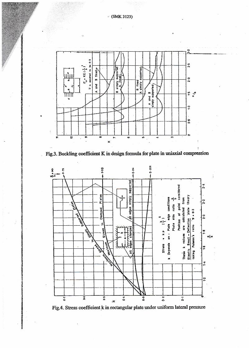
wie the rclativo usrgia about 119o. Assrme E * 210 GPa, aud u* Fig3 and
Fig;4 to obtain buckling coefficient (K) and bending $tress coefficient (k)
resry'tively. (A marks)
Fig.2. The geometrythe panel
. (sMK 3123)
i
. Fie.3. Buckling coefficicnt K in design formula for platc in rniaxial comprcssisn
;
rtlr {o.:(€
F"
oI
dl6
o6
{Io
{
N
oN
e
ol-
oN
o*
I
9
gro
E?ac>
PalaSebolor*LE5s !--5 E e!; I;..E;F:': !'i .t:r.FDl- o u .=l
- r o E il ^F f E E;I?
a ol sr - r rl-' 5 ;;l g
! ! ::li-u, E oll 9
O -!i nl:t, €t r_ = EIS
Fig.4. Stress coefficientkin rectangular plate under uniform trateral pressure
. (sMK 3r23)
Ouestion 4
4a. Describe what are the ultimate stress and buckling stress in a column buckling
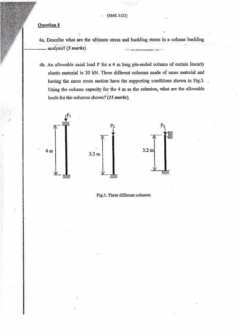
4b. An allowable axial load P for a 4 rn long pia-ended colurnn of certain linearly
etrastic material is 20 kN. Three different columns made of same material and
having the same cross secti.on have the supporting conditions shown in Fig.5.
Using the eolumn capacity for the 4 nn as the criterion, what are &e allowable
loads for the columns shown? (-tr 5 marks).
{I {I ffFig.5. Three different columns
{5 *a,rks}