mathcad based printed microwave lpf …mathcad based printed microwave lpf simulation package...
TRANSCRIPT
MATHCAD Based Printed Microwave LPFSimulation Package
Mazlina Esa, Noor Azlina Hashim and Gunabalan KanthanJabatan Kejuruteraan Perhubungan Radio, Fakulti Kejuruteraan Elektrik,Vniversiti Teknologi Malaysia, 81310 VIM Skudai, Johor DT, Malaysia
e-mail: [email protected]
Abstract- A simulation package for a printedmicrowave low pass filter (LPF) based on tbe powerfulmathematical solver MatbCAD Premium 2000 bas beendeveloped. The chosen structure of the LPF is thestepped-impedance type. Tbe developed package ismainly intended for student usage in tbe MicrowaveLaboratory of Universiti TekDologi Malaysia. However,assignments for the Microwave subject can also be givento undergraduate students. Challenging assignmentsmay be given to tbe Masters students for. tbeirMicrowavelRF subject. Tbe development of sucbeducational design and simulation package belps tbeuniversity in saving large amount of costs for buyinglaboratory experimental set-ups.
formulations allow the frequency response to be computed,Presentation in the form of attenuation or insertion lossversus frequency can be easily displayed.
II. LPF DESIGN PRINCIPLES
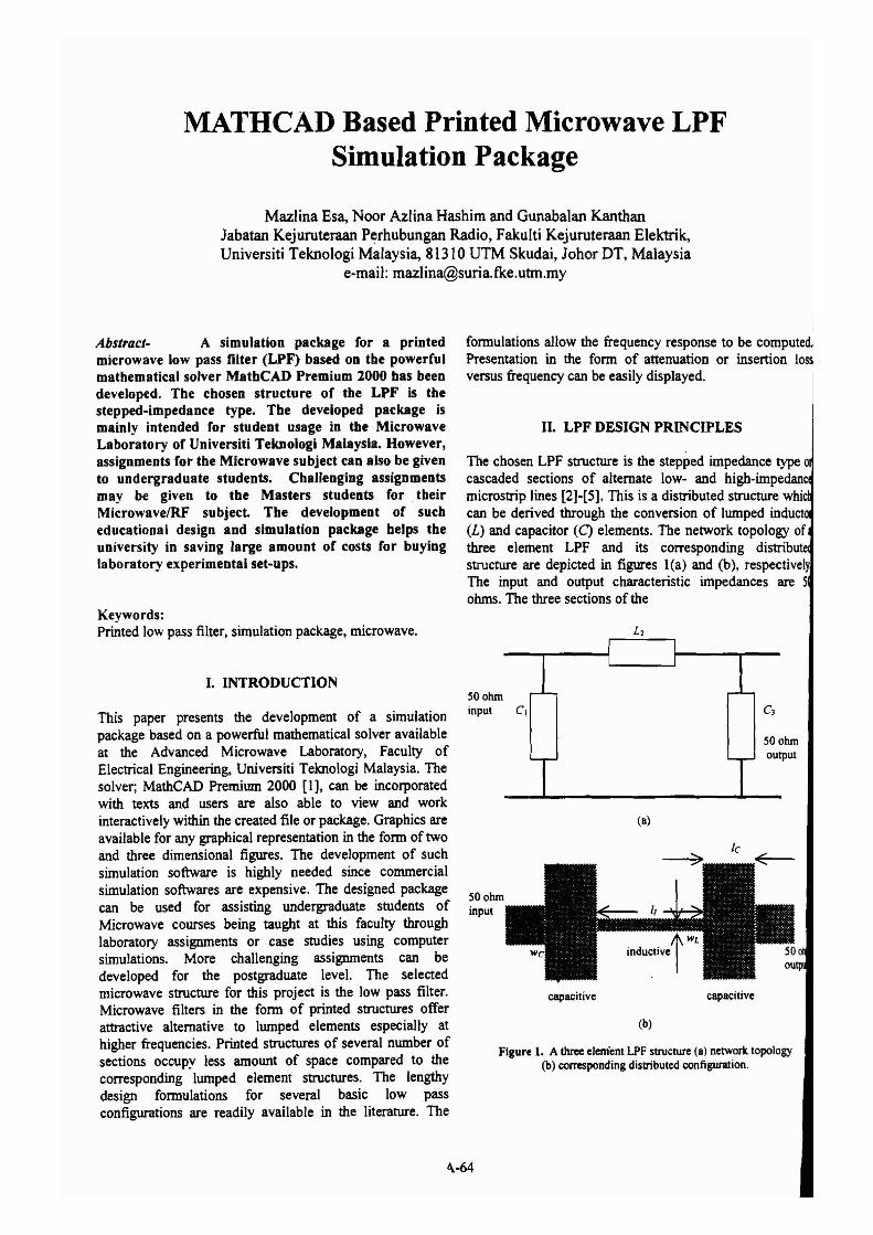
The chosen LPF structure is the stepped impedance typecascaded sections of alternate low- and high-impedanmicrostrip lines [2]-[5]. This is a distributed structure whiecan be derived through the conversion of lumped induct(L) and capacitor (C) elements. The network topology ofthree element LPF and its corresponding distributstructure are depicted in figures I(a) and (b), respectivelyThe input and output characteristic impedances are 5ohms. The three sections of the
(a)
Figure 1. A three element LPF structure (a) networic topology(b) corresponding distributed configuration.
SO ohmoutput
capacitive
(b)
capacitive
SO ohminput
SO ohminput C1This paper presents the development of a simulation
package based on a powerful mathematical solver availableat the Advanced Microwave Laboratory, Faculty ofElectrical Engineering, Universiti Teknologi Malaysia. Thesolver; MathCAD Premium 2000 [I], can be incorporatedwith texts and users are also able to view and workinteractively within the created file or package. Graphics areavailable for any graphical representation in the form of twoand three dimensional figures. The development of suchsimulation software is highly needed since commercialsimulation softwares are expensive. The designed packagecan be used for assisting undergraduate students ofMicrowave courses being taught at this faculty throughlaboratory assignments or case studies using computersimulations. More challenging assignments can bedeveloped for the postgraduate level. The selectedmicrowave structure for this project is the low pass filter.Microwave filters in the form of printed structures offerattractive alternative to lumped elements especially athigher frequencies. Printed structures of several number ofsections occupy less amount of space compared to thecorresponding lumped element structures. The lengthydesign formulations for several basic low passconfigurations are readily available in the literature. The
I. INTRODUCTION
Keywords:Printed low pass filter, simulation package, microwave.
<\-64
corresponding distributed configuration are made up oflengths and widths determined using specific formulationsavailable in the literature.
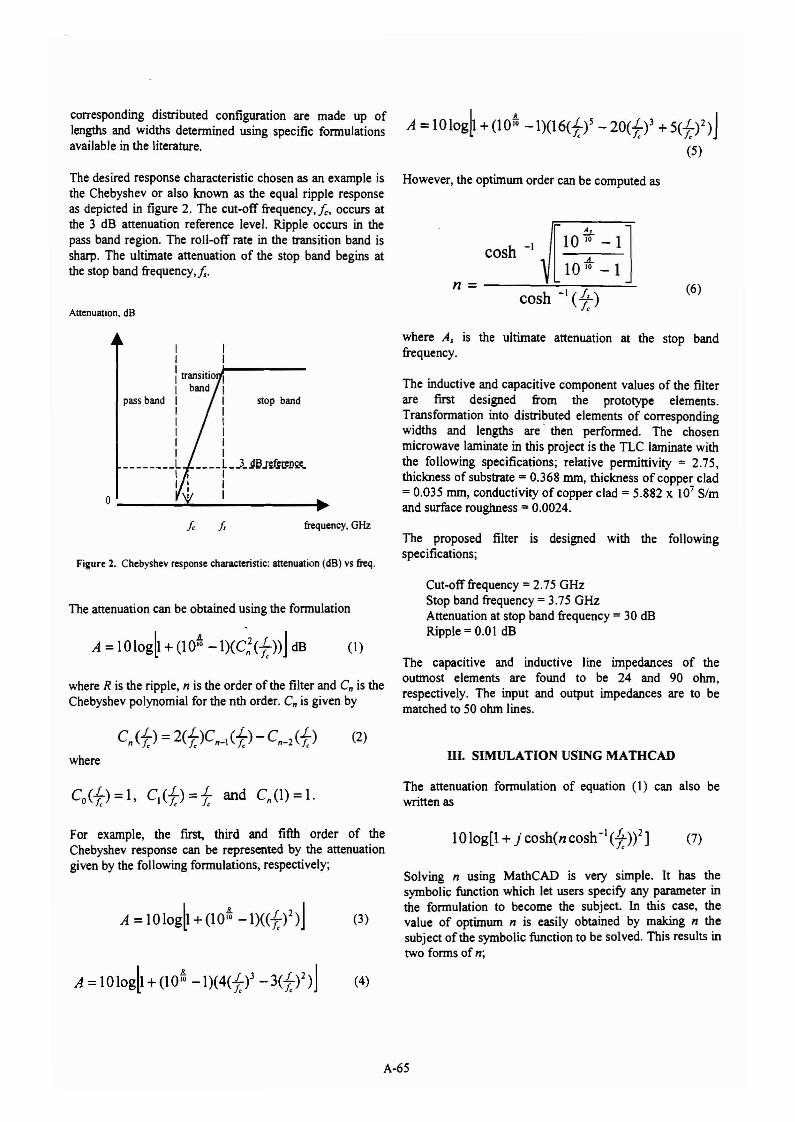
The desired response characteristic chosen as an example isthe Chebyshev or also known as the equal ripple responseas depicted in figure 2. The cut-off frequency,!c, occurs atthe 3 dB attenuation reference level. Ripple occurs in thepass band region. The roll-off rate in the transition band issharp. The ultimate attenuation of the stop band begins atthe stop band frequency, Is.
Attenuation, dB
However, the optimwn order can be computed as
[10 ~: - 1]cosh -I .....
10 10- 1
n = -----':....=.-~----:=-
cosh -I (lL)Ie
(6)
II II ...~-----1transltIO II band I
pass band 1 1 stop bandI 1I II 1I II I________L L__t~~J£~~D~_I I II I I
o ...* 1 .......
where AI is the ultimate attenuation at the stop bandfrequency.
The inductive and capacitive component values of the filterare first designed from the prototype elements.Transformation into distributed elements of correspondingwidths and lengths are' then performed. The chosenmicrowave laminate in this project is the TLC laminate withthe following specifications; relative permittivity = 2.75,thickness of substrate = 0.368 nun, thickness of copper clad= 0.035 nun, conductivity of copper clad = 5.882 x 10⁷ Slmand surface roughness = 0.0024.
Figure 2. Chebyshev response characteristic: attenuation (dB) vs freq.
fc it frequency, GHzThe proposed filter is designed with the followingspecifications;
The attenuation can be obtained using the formulation
where R is the ripple, n is the order of the filter and Cn is theChebyshev polynomial for the nth order. Cn is given by
(2)
where
For example, the first, third and fifth order of theChebyshev response can be represented by the attenuationgiven by the following formulations, respectively;
Cut-off frequency =2.75 GHzStop band frequency = 3.75 GHzAttenuation at stop band frequency = 30 dBRipple = 0.01 dB
The capacitive and inductive line impedances of theoutmost elements are found to be 24 and 90 ohm,respectively. The input and output impedances are to bematched to 50 ohm lines.
III. SIMULATION USING MATHCAD
The attenuation formulation of equation (1) can also bewritten as
lOlog[l+ jcosh(ncosh-1(i))2] (7)
Solving n using MathCAD is very simple. It has thesymbolic function which let users specify any parameter inthe formulation to become the subject. In this case, thevalue of optimwn n is easily obtained by making n thesubject of the symbolic function to be solved. This results intwo forms of n;
A-65
and
cosh-'[7~j(exp(r, A, In10)-1)]
COSh-'(~ J
COSh-'[-]~j(exp(r, A, In 10)-1)]
COSh-,(~J
(8)
(9)
However, only the first solution is valid for computation ofn since this yields positive value. Formulations (8) and (6)are indeed identical.
IV. COMMERCIAL NUMERICAL SIMULATION
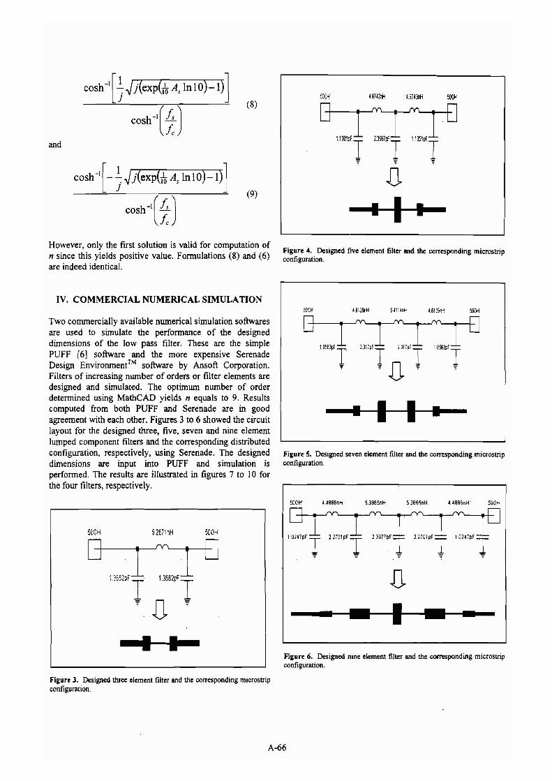
Two commercially available numerical simulation softwaresare used to simulate the performance of the designeddimensions of the low pass filter. These are the simplePUFF [6] software and the more expensive SerenadeDesign Environment™ software by Ansoft Corporation.Filters of increasing number of orders or filter elements aredesigned and simulated. The optimum number of orderdetermined using MathCAD yields n equals to 9. Resultscomputed from both PUFF and Serenade are in goodagreement with each other. Figures 3 to 6 showed the circuitlayout for the designed three, five, seven and nine elementlumped component filters and the corresponding distributedconfiguration, respectively, using Serenade. The designeddimensions are input into PUFF and simulation isperformed. The results are illustrated in figures 7 to 10 forthe four filters, respectively.
Figure 4. Designed five element filter and the corresponding microstripconfiguration.
-··-H~·-
Figure 5. Designed seven element filter and the corresponding microstripconfiguration.
500H 52671 nH 50W
SON! U888n" 5.38SSnH S386~nH 4488;;nH 5DO~
13652PF
TD~
D--..---··-....il-......·.._--t---·
Figure 3. Designed three element filter and the corresponding microstripconfiguration.
Figure 6. Designed nine element filter and the corresponding microstripconfiguration.
A-66
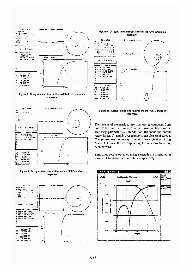
Figure 7. Designed three element filter and the PUFF simulationresponses,
./
. "rlle ; ~tlc
sr·'II
I~B i
I II
i 1\-18~~--------;r-'GiZ=.........L.--------,Jsl
r---'I : lAYOUT
j ijJ p.a~""f_~~""''''''
F2 : 'LOTPoin-ts 21SfIIith 1"'8diu~ 1
f ·Jl.~~ gt.l;:--S11 "q.". j,.; <1
> S1.2 ~,,:. l'S21 "' i~ ," 1.,>, <'(
+522 -'C l'
Figure 9. Designed seven element filter and the PUFF simulationresponses.
:1 H"'flr:~'
'.. 58,_ g,I. 2,7".>8 (;Hz
ur 8.7'"..>8h 8.368 _
'. 178,_ ..r: 8.88fI _
TAb lIir.rol.-t .. ip
~"~'--'-"""--'~""""--""']"
tiM! 8.2 _eelS
....-r.. . ....
F3 : PARTS• tl ine 580 :za.~ tl inc 240 1411Nllc tl inc 1Z.0SI <J.871J11ftd tJ ine 38n 8.374Nte tJ ine 99nlZ,.r tljne 980: tS.~9hi
t aIe : 3aect.lc-_.-.0:
i
-16~>- "-_---'1-;_=----------;!
, -:-- " : IAVOUT , "
r '
I "Gil.
" ,l~'"
:;It!; !:i.8.b66 Qrtl 2.7S8 Qi;,r;
or Z.7S8It 8.::U:,f.1 _
~ 188,~ ...(~ tR.iU'I8 _Ta~ .icrost,. ip
F3 : 'ARTS~ tline~l:Z .ls.....b tJ me ZtQ (,.6'32,"",c t)Jne- 9tm 17 ,2.2.....,\·I9
"
F2 'LOT:Points ZlSforlit.h ,..l\,diu~ J
tr,SU)' S1l
S21+SZZ
Simulation results obtained using Serenade are illustrated infigures 11 to 14 for the four filters, respectively.
The inverse of attenuation, insertion loss, is computed fromboth PUFF and Serenade. This is shown in the fonn ofscattering parameter, 8 12, In addition, the input and outputreturn losses, 8 11 and 822, respectively, can also be observed.The return loss responses have not been obtained usingMathCAD since the corresponding fonnulations have notbeen derived.
Figure 10. Designed nine element filter and the PUFF simulationresponses,
> '
I i Ie : s..ocUc
lS~:;-i------''----.--;=----------,J
~rl
l~.._b, u lUI d ~.,-.,.
,
F2 PLOTPoinh Zl&-it.h r"/td lu~ 1
r wb:~Sll
x Sl2.$21
+8"l2
I .''' ~
;z.d 58.8fttII IIil. 2,?'"..ll (:liz1e r' 2.7'"..1oA'II 8.:if.of) J'IfIl
t88.B8tI ...!c 8.B8t!J ....Tab .jcrost .. ip
I,,~r~:_ ,~~:~'"JF3 'MTS
II t 1 ilW' 5f.K) 2f»t""h tline Z",O ~'."J9t'lfot
c t lllle Ll.g ~) .9M_d tline fJ8R 14""·r•h
...-...
~i',
",
..
..,...---:----.::r------:c:::;;;;iIIIII~
i!!
-280!;-------'----;r·_=----------,J
,S,.Bk'\~yt<:
2.d 58.888 Qrd 2.7S8 Gtb:er 2.?S8h 8.3bB ...
US.8M! ..c 8.888 ..ra~ .Jcr-orl,..p
Figure 8. Designed five element filter and the PUFF simulationresponses.
7~~·f:':·7'- 'i'" ~~l~""-.-,-- t-_· ..··- I'• tli~~P= Ib t.line 2.040 'i.837... Iii. : 7.-:tlcr. t.Une 12.8Q: 5 .8~ r-:-- -.,---,,_-------..,• t.1 hae 98n 13a1l1 8 i
~ llhlll qeg 1&.&91- I•"
A-67
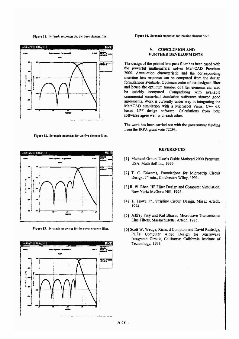
Figure 11. Serenade respOnses for the three element filter.
J~IN"'IIS2111 dU/NdqfSllll P1I1JEl-
-Figure 12. Serenade responses for the five element filter.
-'!'d,~---::_---:-:r-----,:r---:i-
Figure 14. Serenade respOnses for the nine element filler.
V. CONCLUSION ANDFURTHER DEVELOPMENTS
The design of the printed low pass filter has been eased withthe powerful mathematical solver MathCAD Premium2000. Attenuation characteristic and the correspondinginsertion loss response can be computed from the designformulations available. Optimum order of the designed filterand hence the optimum number of filter elements can alsobe quickly computed. Comparisons with availablecommercial numerical simulation softwares showed goodagreements. Work is currently under way in integrating theMathCAD simulation with a Microsoft Visual C++ 6.0based LPF design software. Calculations from bothsoftwares agree well with each other.
The work has been carried out with the government fundingfrom the IRPA grant vote 72293.
REFERENCES
[l} Mathcad Group, User's Guide Mathcad 2000 Premium,USA: Math Soft Inc, 1999.
[2} T. C. Edwards, Foundations for Microstrip CircuitDesign, 2nd ecln., Chichester: Wiley, 1991.
[3] R. W. Rhea, HF Filter Design and Computer Simulation,New York: McGraw Hill, 1995.
[4} H. Howe, Jr., Stripline Circuit Design, Mass.: Artech,1974.
[5} Jeffrey Frey and Kul Bhasin, Microwave TransmissionLine Filters, Massachusetts: Artech, 1985.
-
Figure 13. Serenade respOnses for the seven element filler.
-_...,....-
[6} Scott W. Wedge, Richard Compton and David Rutledge,PUFF Computer Aided Design for MicrowaveIntegrated Circuit, California: California Institute ofTechnology, 1991.
-A-68 .