dep.teknik mesinfile.upi.edu/direktori/fptk/jur._pend._teknik_mesin/... · –assists in removal of...
TRANSCRIPT
DASAR GMAWSumber naskah
Gas Metal Arc Welding
Metal Inert Gas
Wanda sue Benton
ESAB University & Florence-Darlington Technical College
DEP.TEKNIK MESIN
PPPPTK BMTI BANDUNG
2009
Prepared by:
Ahmad Nurdin
Yusuf Tinting Sirenden
Objectives
Gambaran umum pengoperasian GMAW
Gambaran umum cacat dalam pengelasan
GMAW
Mendemonstrasikan, menggunakan, dan
troubleshooting peralatan
Mendemonstrasikan teknik pengelasan
Mengelas pelat baja lunak pada berbagai
posisi
Introduction
GMAW adalah didefinisikan sebagai busur
cahaya menggunakan satu elektroda dapat
dimakan yang secara kontinyu memberi
makan dan satu gas pelindung.
GMAW adalah juga dikenal sebagai MIG
(Gas mulia Logam).
Hasil pengelasan kualitasnya lebih tinggi
Hasilkan produktivitas tinggi
KEUNTUNGAN
Mudah dalam pengisian celah atau
gap
Pengelasan dapat dilakukan dalam
semua posisi
Tidak ada / sedikit slag atau terak
Kecepatan las yang Tinggi
Kualitas tinngi
Lebih sedikit / kecil distorsi
Types of Metal Transfer
The basic GMAW process includes three
distinctive process techniques:
1. Short Circuit (Short Arc)
2. Globular Transfer
3. Spray Arc Transfer
Short Circuit (Short Arc)
Beroperasi pada tegangan dan arus rendah
Pembekuan-cepat . Kecil kubah genangan
(mengelas)
Cocok dalam pengelasan bahan tipis di/dalam
posisi apapun, demikian pula bahan tebal di/dalam
posisi vertikal dan posisi 'overhead’
Transfer Logam terjadi ketika hubungan singkat
listrik stabil
Globular Transfer
Arus dan kecepatan kawat las terjadi maksimum
diatas short arc .
Cairan logam terjadi lebih besar dari diameter
kawat yang sedang digunakan
Spater terjadi saat ini pengelasan lebih banyak
Cocok untuk Pengelasan terjadi secara efektif bila
dilakukan pada posisi flat ketika menggunakan
transfer berbentuk bulat
Spray Arc Transfer
Terjadi ketika arus dan setting tegangan
yang digunakan lebih tinggi dari Globular
Transfer
Cocok Digunakan pada material tebal, pada
posisi flat
Spater / Percikan sedikit
Manual GMAW Equipment
Three major elements are :
1.) Welding torch and accessories
2.) Welding control & Wire feed motor
3.) Power Source
GMAW equipment can be used either
manually or automatically
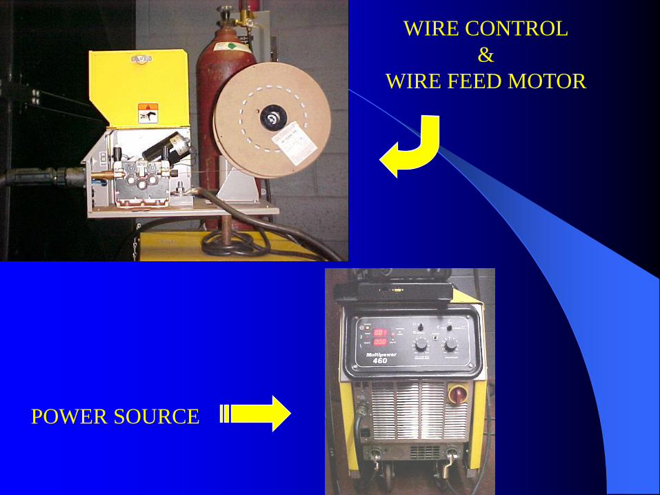
WIRE CONTROL
&
WIRE FEED MOTOR
POWER SOURCE
Welding Torch & Accessories
The welding torch guides the wire and
shielding gas to the weld zone.
Brings welding power to the wire also
Major components/parts of the torch are the
contact tip, shielding gas nozzle, gas
diffuser, and the wire conduit
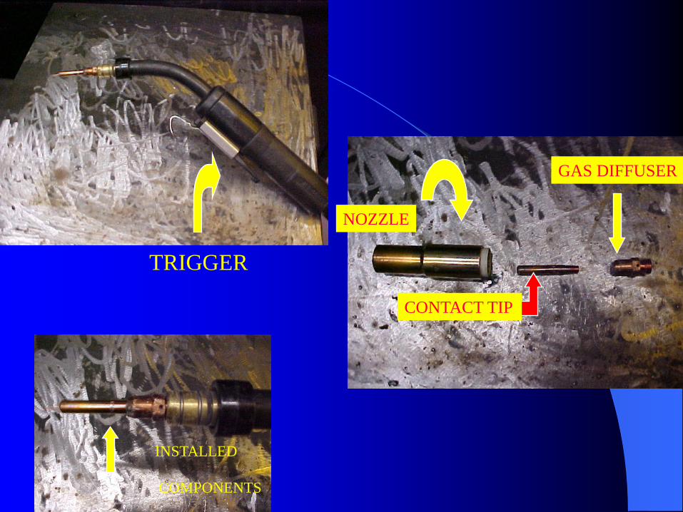
TRIGGER
INSTALLED
COMPONENTS
NOZZLE
CONTACT TIP
GAS DIFFUSER
Welding Control & Wire
Feed Motor
Welding control & Wire feed motor are
combined into one unit
Main function is to pull the wire from the
spool and feed it to the arc
Controls wire feed speed and regulates the
starting and stopping of wire feed
Wire feed speed controls Amperage
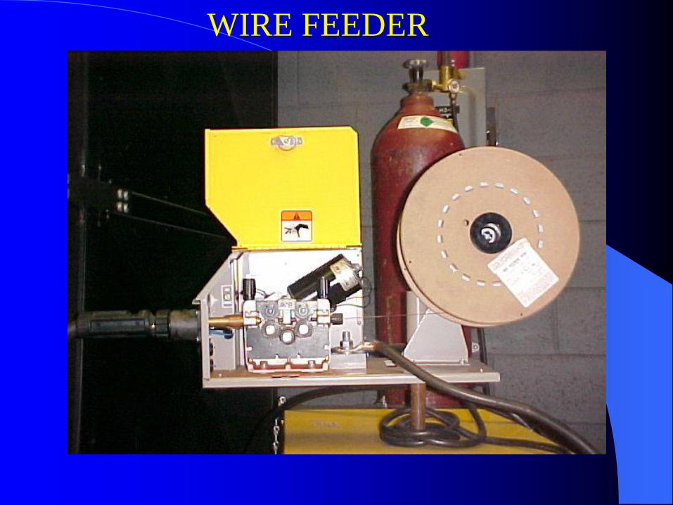
WIRE FEEDER
Power Source
Almost all GMAW is done with reverse polarity also known as DCEP
Positive (+) lead is connected to the torch
Negative (-) lead is connected to the work piece
Provides a relatively consistent voltage to the arc
Arc Voltage is the voltage between the end of the wire and the work piece
22 - 17
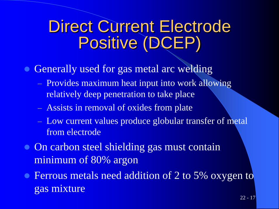
Direct Current Electrode Positive (DCEP)
Generally used for gas metal arc welding
– Provides maximum heat input into work allowing
relatively deep penetration to take place
– Assists in removal of oxides from plate
– Low current values produce globular transfer of metal
from electrode
On carbon steel shielding gas must contain
minimum of 80% argon
Ferrous metals need addition of 2 to 5% oxygen to
gas mixture
22 - 18
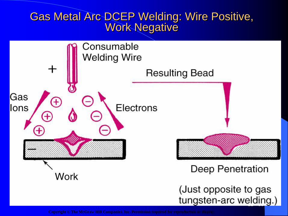
Gas Metal Arc DCEP Welding: Wire Positive, Work Negative
Copyright © The McGraw-Hill Companies, Inc. Permission required for reproduction or display.
22 - 19
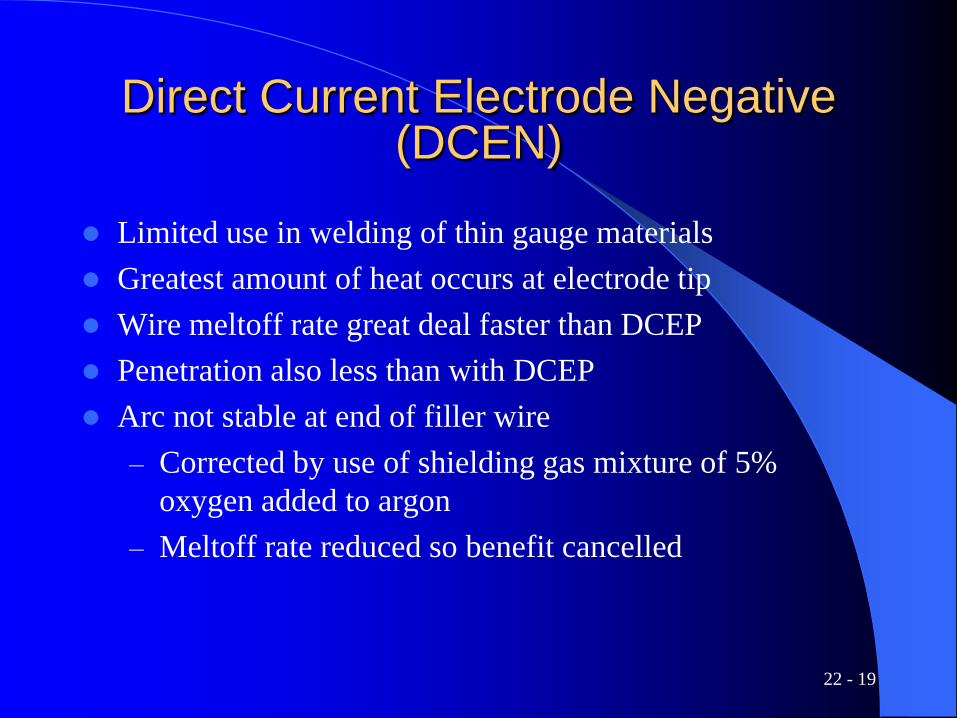
Direct Current Electrode Negative (DCEN)
Limited use in welding of thin gauge materials
Greatest amount of heat occurs at electrode tip
Wire meltoff rate great deal faster than DCEP
Penetration also less than with DCEP
Arc not stable at end of filler wire
– Corrected by use of shielding gas mixture of 5%
oxygen added to argon
– Meltoff rate reduced so benefit cancelled
22 - 20
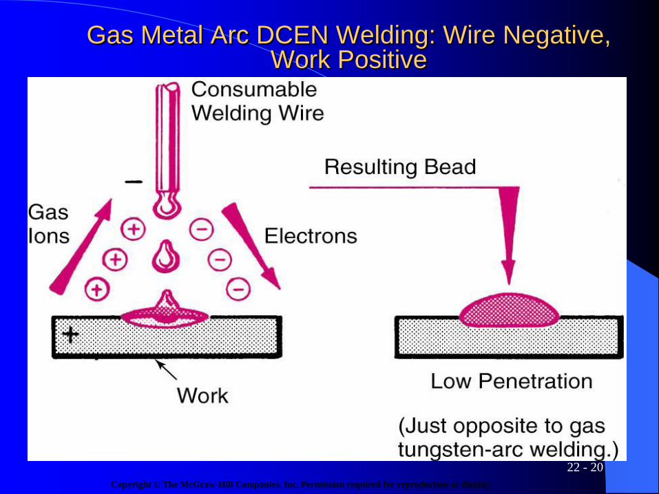
Gas Metal Arc DCEN Welding: Wire Negative, Work Positive
Copyright © The McGraw-Hill Companies, Inc. Permission required for reproduction or display.
22 - 21
Alternating Current
Jarang digunakan dalam GMAW
Busur tidak stabil oleh karena terjadi arus
balik
Kombinasi keduanya, yaitu polaritas DCEN
dan DCEP, terjadi polaritas pada penetrasi
Digunakan untuk pengelasan aluminium
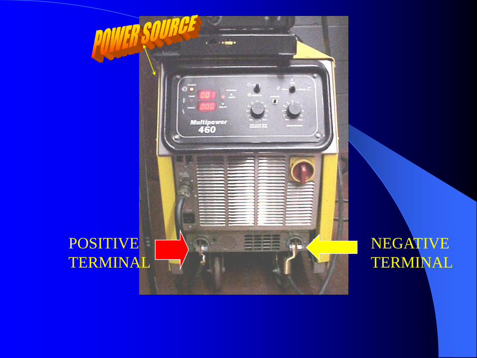
POSITIVE
TERMINAL
NEGATIVE
TERMINAL
Shielding Gases
Purpose of shielding gas is the protect the weld area from the contaminants in the atmosphere
Gas can be Inert, Reactive, or Mixtures of both
Gas flow rate is between 25-35 CFH
Argon, Helium, and Carbon Dioxide are the main three gases used in GMAW
22 - 24
Shielding Gas Argon and helium first used for gas metal
arc
– Continue to be basic gases
Argon used more than helium on ferrous metals to keep spatter at minimum
– Also heavier than air so good weld coverage
Oxygen or carbon dioxide added to pure gases to improve arc stability, minimize undercut, reduce porosity, and improve appearance of weld
22 - 25
Shielding Gas
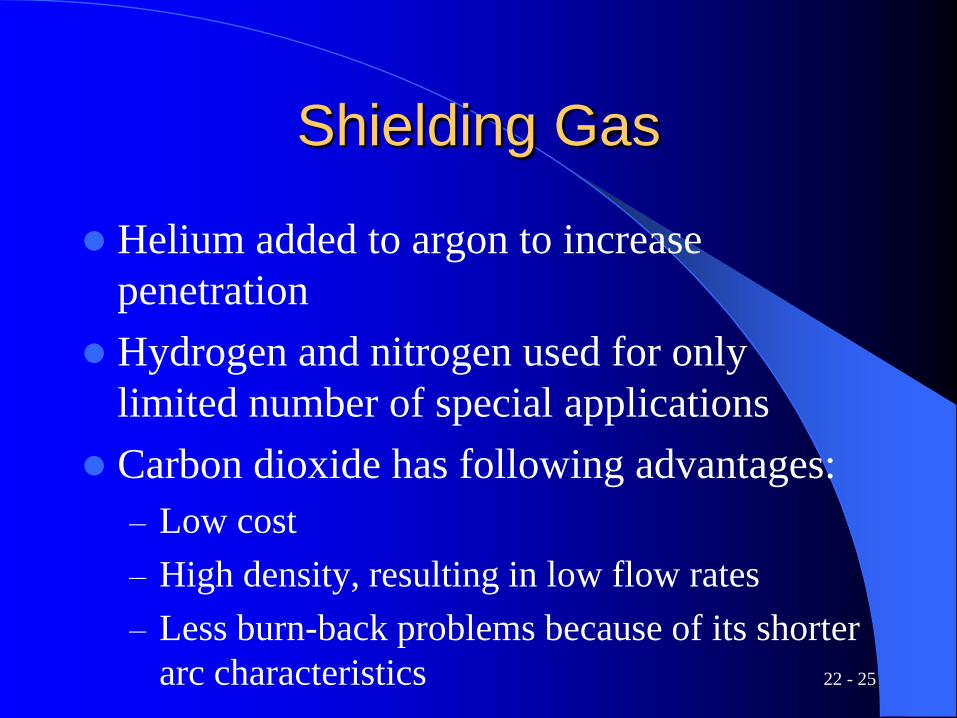
Helium added to argon to increase
penetration
Hydrogen and nitrogen used for only
limited number of special applications
Carbon dioxide has following advantages:
– Low cost
– High density, resulting in low flow rates
– Less burn-back problems because of its shorter
arc characteristics

22 - 26
Specific Metal Recommendations
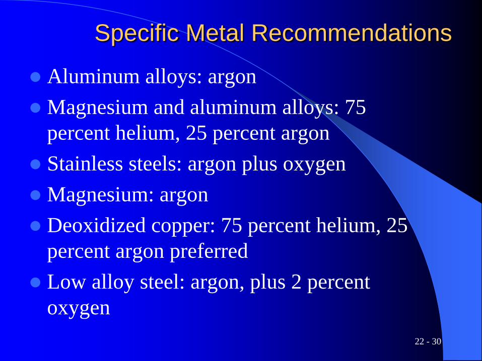
Aluminum alloys: argon
Magnesium and aluminum alloys: 75
percent helium, 25 percent argon
Stainless steels: argon plus oxygen
Magnesium: argon
Deoxidized copper: 75 percent helium, 25
percent argon preferred
Low alloy steel: argon, plus 2 percent
oxygen
22 - 27
Specific Metal
Recommendations
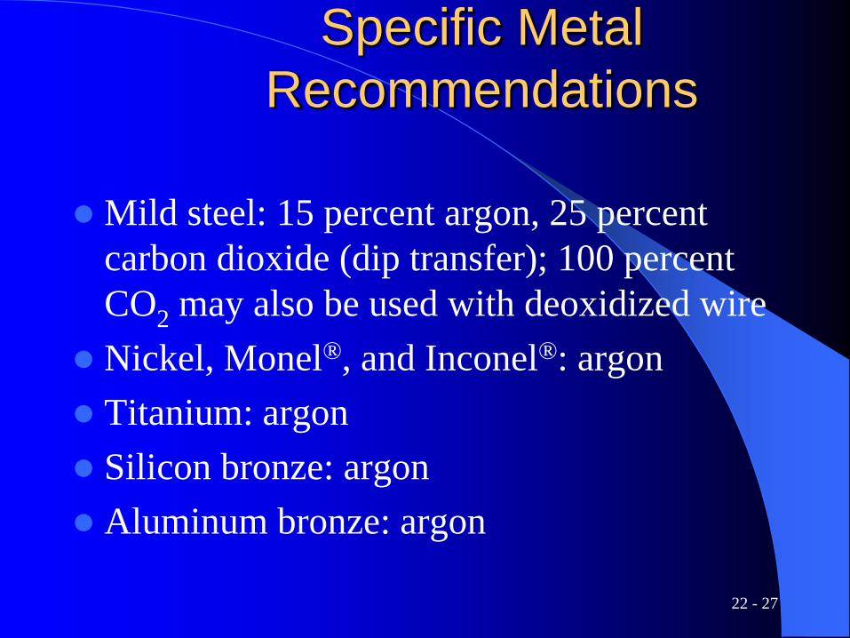
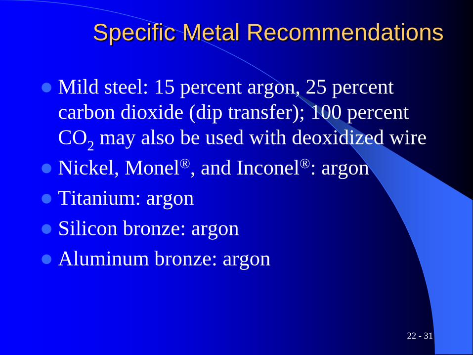
Mild steel: 15 percent argon, 25 percent
carbon dioxide (dip transfer); 100 percent
CO2 may also be used with deoxidized wire
Nickel, Monel®, and Inconel®: argon
Titanium: argon
Silicon bronze: argon
Aluminum bronze: argon
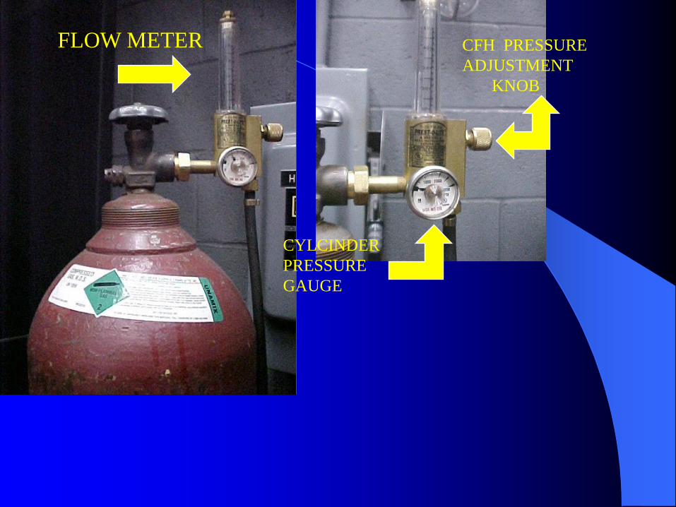
FLOW METER
CYLCINDER
PRESSURE
GAUGE
CFH PRESSURE
ADJUSTMENT
KNOB
22 - 30
Specific Metal Recommendations
Aluminum alloys: argon
Magnesium and aluminum alloys: 75
percent helium, 25 percent argon
Stainless steels: argon plus oxygen
Magnesium: argon
Deoxidized copper: 75 percent helium, 25
percent argon preferred
Low alloy steel: argon, plus 2 percent
oxygen
22 - 31
Specific Metal Recommendations
Mild steel: 15 percent argon, 25 percent
carbon dioxide (dip transfer); 100 percent
CO2 may also be used with deoxidized wire
Nickel, Monel®, and Inconel®: argon
Titanium: argon
Silicon bronze: argon
Aluminum bronze: argon
22 - 32
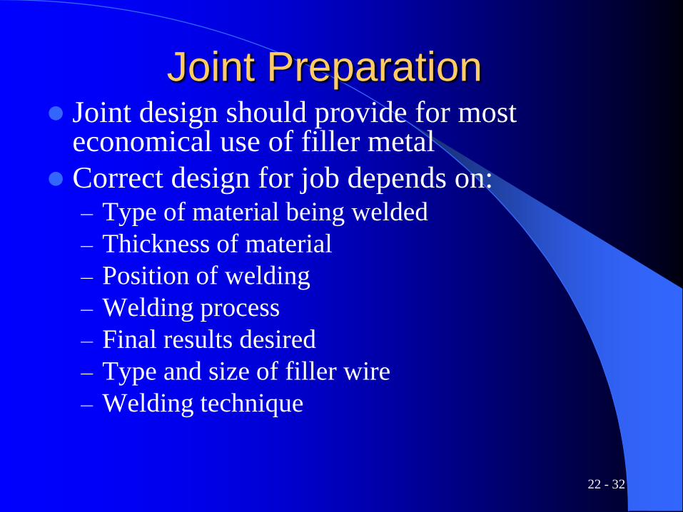
Joint Preparation Joint design should provide for most
economical use of filler metal
Correct design for job depends on:– Type of material being welded
– Thickness of material
– Position of welding
– Welding process
– Final results desired
– Type and size of filler wire
– Welding technique
22 - 33
Joint Preparation
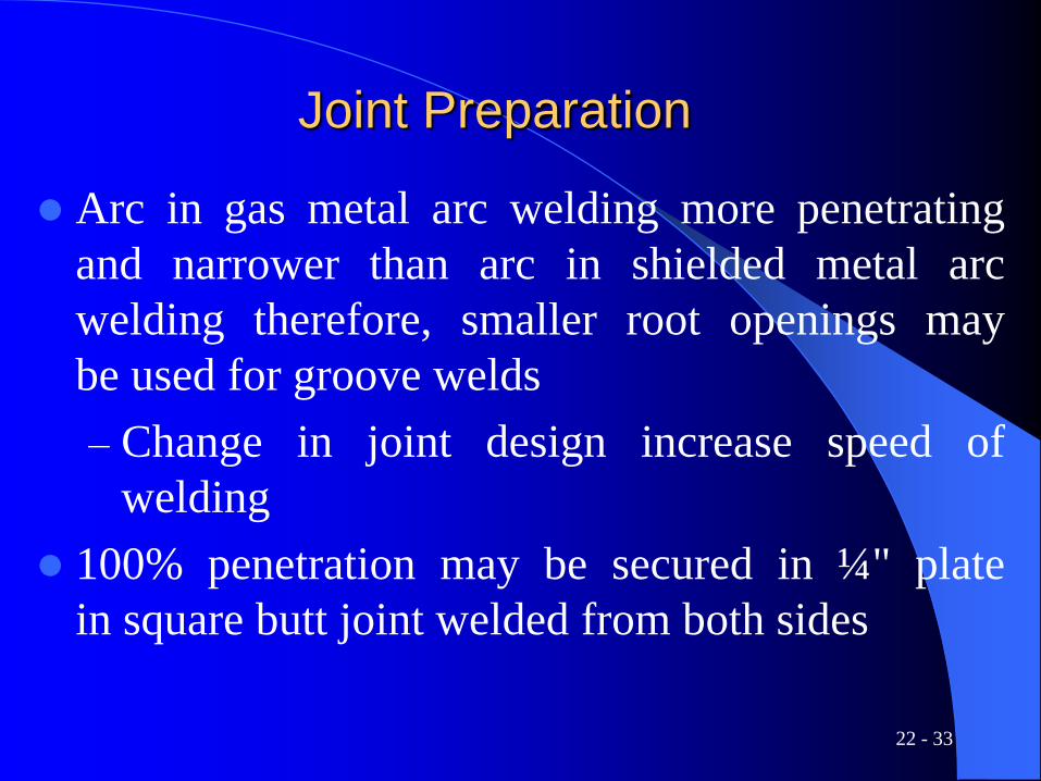
Arc in gas metal arc welding more penetrating
and narrower than arc in shielded metal arc
welding therefore, smaller root openings may
be used for groove welds
– Change in joint design increase speed of
welding
100% penetration may be secured in ¼" plate
in square butt joint welded from both sides
22 - 34
Joint Preparation
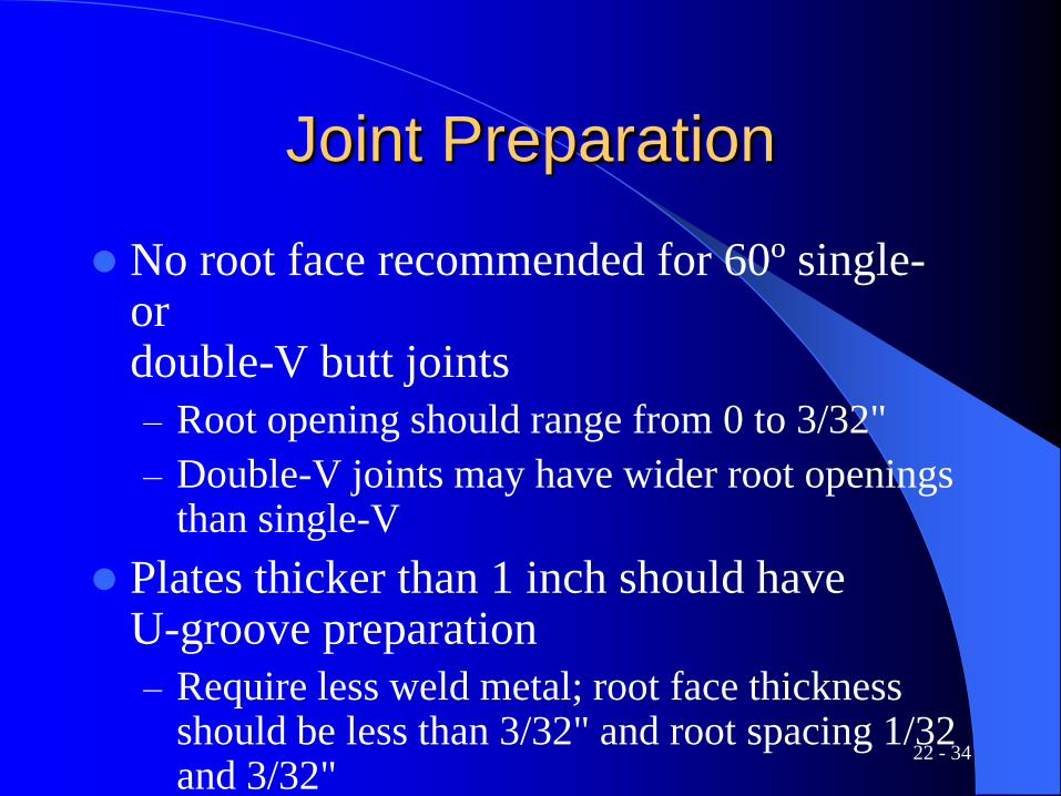
No root face recommended for 60º single-or double-V butt joints
– Root opening should range from 0 to 3/32"
– Double-V joints may have wider root openings than single-V
Plates thicker than 1 inch should have U-groove preparation
– Require less weld metal; root face thickness should be less than 3/32" and root spacing 1/32 and 3/32"
22 - 35
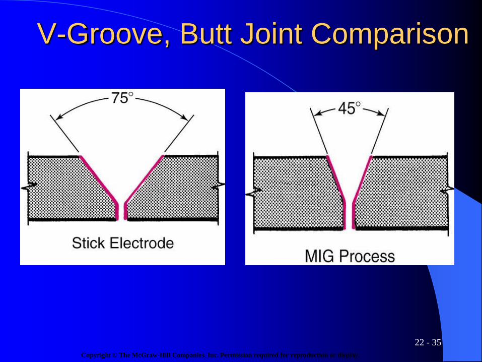
V-Groove, Butt Joint Comparison
Copyright © The McGraw-Hill Companies, Inc. Permission required for reproduction or display.
Multipass mengelas lebih mudah karena sedikit terak,
memastikan pembersihan lebih mudah
Untuk Sambungan Fillet, permukaan deposit las lebih
sedikit/ kecil pada permukaan material
Jenis sambungan Tertentu ditarik mundur untuk
mencegah terjadinya penyumbatan pada torch
Joint Preparation
22 - 37
Joint Preparation
Multipass welding easier since absence of slag
ensures easier cleaning
For fillet welds deposit smaller weld beads on
surface of material
Certain types of joints backed up to prevent
weld from projecting through back side
– Blocks, strips and bars of copper, steel or ceramics
22 - 38
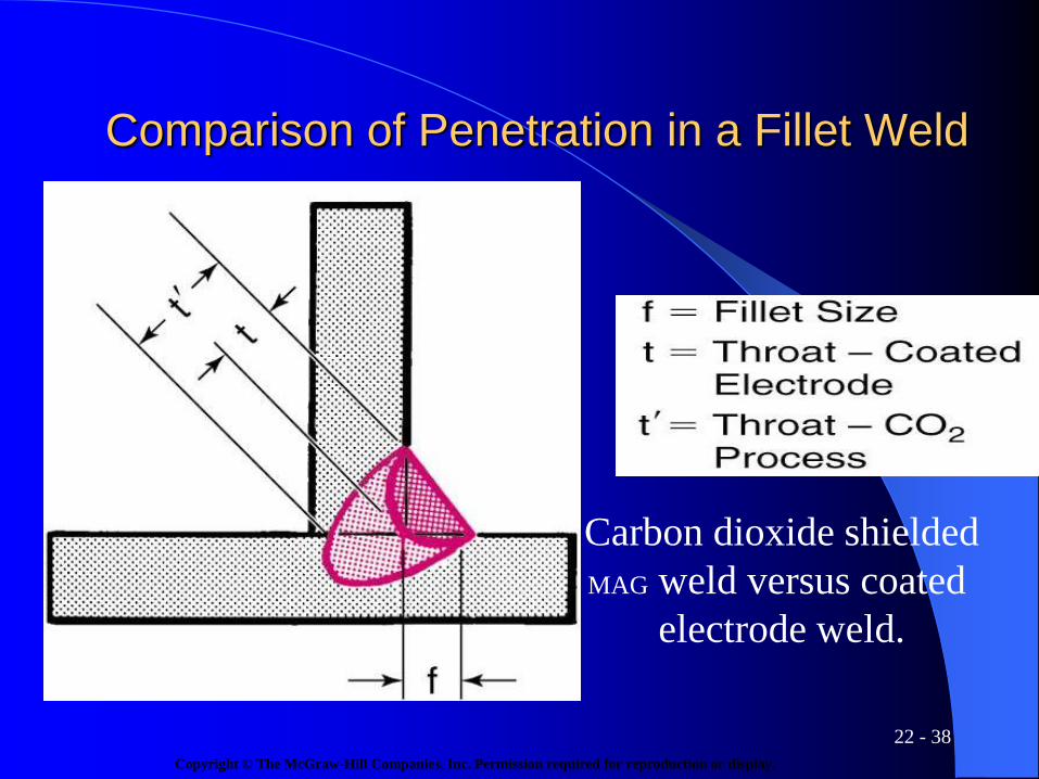
Comparison of Penetration in a Fillet Weld
Carbon dioxide shielded
MAG weld versus coated
electrode weld.
Copyright © The McGraw-Hill Companies, Inc. Permission required for reproduction or display.
22 - 39
Electrode Diameter
Influences size of weld bead, depth of penetration, and speed of welding
General rule
– For same current, arc becomes more penetrating as electrode diameter decreases and deposition rate increases
To get maximum deposition rate at given current density, use smallest wire possible consistent with acceptable weld profile
Wire 0.045" and larger provide lower deposition rate and deposit wider beads than small wires
22 - 40
Electrode Diameter
Filler wires should be same composition as materials being welded
Position of welding may affect size of electrode
Welding thin material– Wires with diameters: 0.023/0.025, 0.030, 0.035"
Medium thick materials– Wires with diameters: 0.045" or 1/16"
Heavy materials– Wire with diameter: 1/8"
Small diameters recommended for vertical and overhead positions
22 - 41
Electrode Extension
Length of filler wire that extends pas contact tube
Area where preheating of filler wire occurs
Also called the stickout
Controls dimensions of weld bead since length of extension affect burnoff rate
Exerts influence on penetration through its effect on welding current– As extension length increased, preheating of wire
increases and current reduced which in turn decreases amount of penetration into work
Stickout distance may vary from 1/8 to 1 1/4"
22 - 42
Electrode Extension
Short electrode extensions (1/8–1/2 inch) used for short circuit mode of transfer, generally with smaller diameter electrodes (0.023–0.045 inches)
Stainless steel favors shorter electrode extension because of its higher resistivity (1/8–1/4 inch)– Longer and larger diameter electrode extensions used
for spray arcs (1/2–11/4 inches)
Excessive long arcs with active gases reduce the
mechanical properties in weld
– Various alloys being burned out as metal transferred
across longer arc

22 - 43
Electrode Extension Tests indicated that when electrode extension
increased from 3/16 to 5/8 inch, welding current then drops approximately 60 amperes
Current reduced because of change in amount of preheating that takes place in wire
– As electrode extension increased, preheating of wire increases
– Thus less welding current required from power source at a given feed rate
– Because of self-regulating characteristics of constant voltage power source, welding current decreased
– As welding current decreased, depth of penetration also decreases
22 - 44
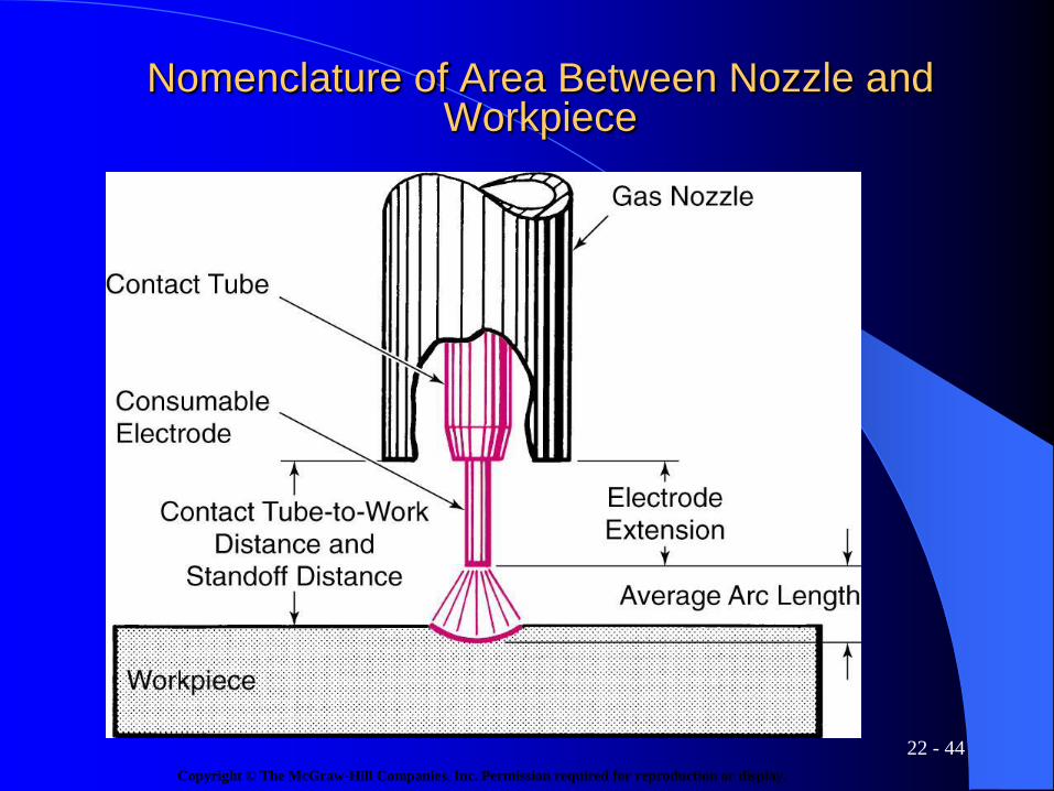
Nomenclature of Area Between Nozzle and Workpiece
Copyright © The McGraw-Hill Companies, Inc. Permission required for reproduction or display.
22 - 45
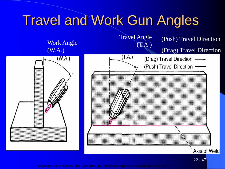
Position of the Gun
Expressed by two angles: travel and work
Bead shape changed by changing direction of wire as goes into joint in line of travel
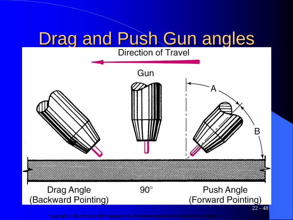
Gun Angle
– Can be compared to angle of electrode in shielded metal arc welding
– Drag technique results in high narrow bead with deeper penetration (10º drag angle)
– As drag angle reduced, bead height decreases, width increases
– Increased travel speeds characteristic of push technique
22 - 46
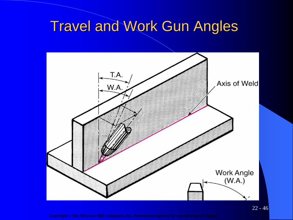
Travel and Work Gun Angles
Copyright © The McGraw-Hill Companies, Inc. Permission required for reproduction or display.
22 - 47
Travel and Work Gun Angles
Copyright © The McGraw-Hill Companies, Inc. Permission required for reproduction or display.
Travel Angle
(T.A.)(Drag) Travel Direction
(Push) Travel DirectionWork Angle
(W.A.)
22 - 48
Drag and Push Gun angles
Copyright © The McGraw-Hill Companies, Inc. Permission required for reproduction or display.
22 - 49
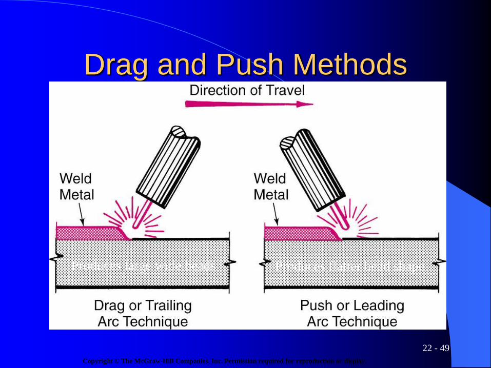
Drag and Push Methods
Produces large wide beads Produces flatter bead shape
Copyright © The McGraw-Hill Companies, Inc. Permission required for reproduction or display.

22 - 51
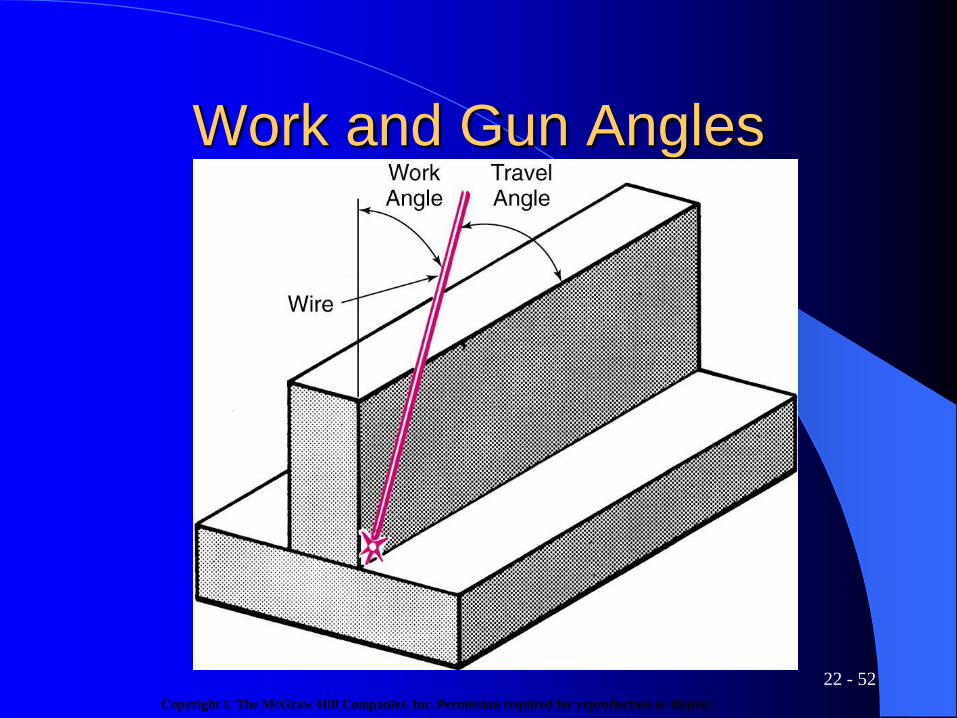
Work Angle
Position of wire to joint in plane perpendicular to line of travel
Filler weld joints: work angle normally half of included angle between plates forming joint
Butt welds: work angle normally 90º to surface of plate being joined
Utilizes natural arc force to push weld metal against vertical surface to prevent undercut and provide good bead contour
22 - 52
Work and Gun Angles
Copyright © The McGraw-Hill Companies, Inc. Permission required for reproduction or display.
22 - 53
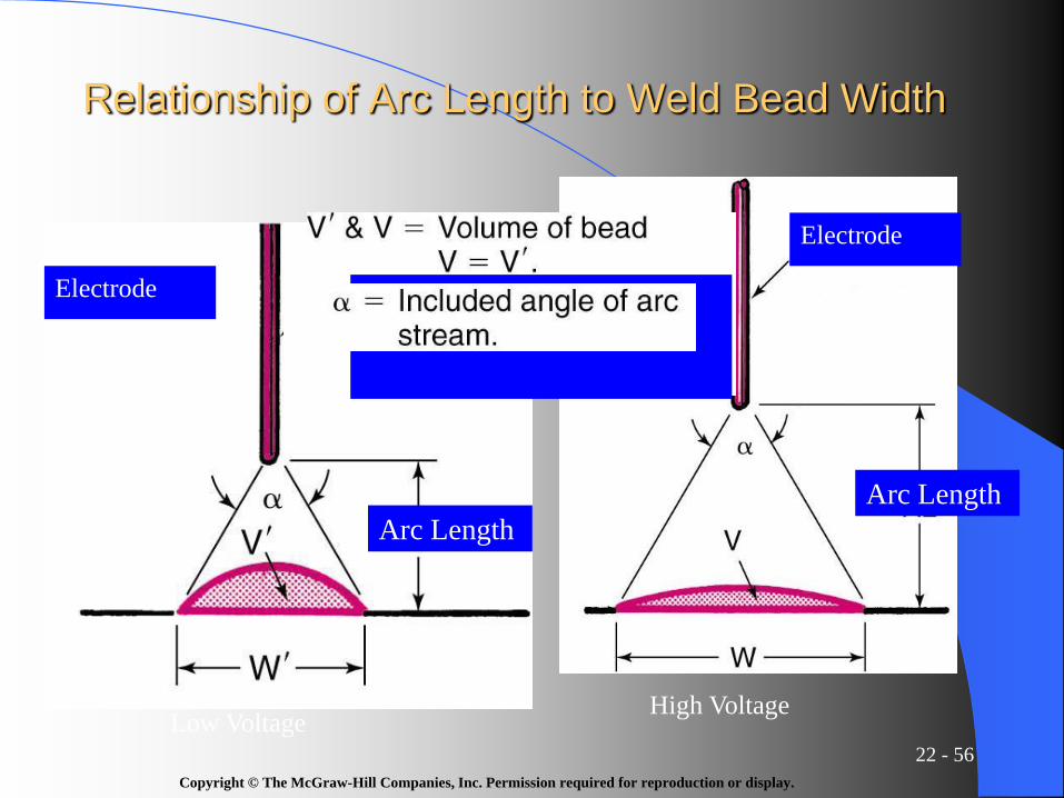
Arc Length Constant voltage welding machine used for gas
metal arc welding provides for self-adjustment of arc length
– Arc length shortened, arc voltage reduced
– Arc length lengthened, arc voltage increased
No change in wire-feed speed occurs
Corrected by automatic increase or decrease of burnoff rate of filler wire
Welder has complete control of welding current and arc length by setting wire-feed speed on wire feeder and voltage on welding machine
22 - 54
Arc Voltage
Decided effect upon penetration, bead height, and bead width
Chief function to stabilize welding arc and provide smooth, spatter-free weld bead
Higher or lower causes arc to become unstable
– Higher: produces wider, flatter bead and increases possibility of porosity and increases spatter and increases undercut in fillet welds
– Lower: causes bead to be high and narrow
22 - 55
Arc Voltage
High arc voltages result in globular transfer
– Spatter prone and reduces deposition efficiency
Has sharp crackling sound when proper arc
voltage for short circuit transfer
– Spray arc have hissing sound
Not set to control penetration
Better control of weld profile and arc
stability
22 - 56
Relationship of Arc Length to Weld Bead Width
Copyright © The McGraw-Hill Companies, Inc. Permission required for reproduction or display.
High VoltageLow Voltage
Arc Length
Arc Length
Electrode
Electrode
22 - 57
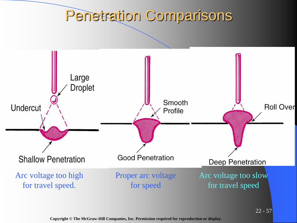
Penetration Comparisons
Copyright © The McGraw-Hill Companies, Inc. Permission required for reproduction or display.
Arc voltage too high
for travel speed.
Arc voltage too slow
for travel speed
Proper arc voltage
for speed
22 - 58
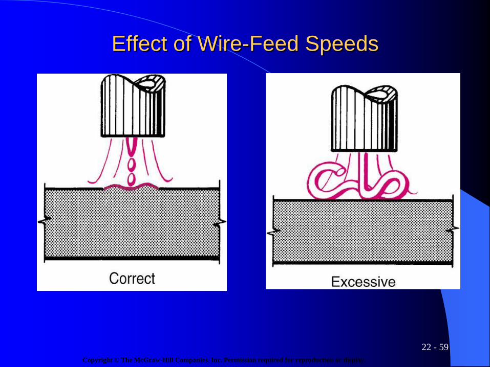
Wire-Feed Speed
Fixed relationship between rate of filler wire burn off and welding current
Electrode wire-feed speed determines welding current
– Current set by wire-feed speed control on wire feeder
Excessive speed, welding machine cannot put out enough current to melt wire fast enough
– Stubbing or roping of wire occurs
– Causes convex weld beads and poor appearance
Decrease in speed results in less electrode being melted
Generally – high setting of filler wire speed rate results in short arc, slow speed in long arc
22 - 59
Effect of Wire-Feed Speeds
Copyright © The McGraw-Hill Companies, Inc. Permission required for reproduction or display.
22 - 60
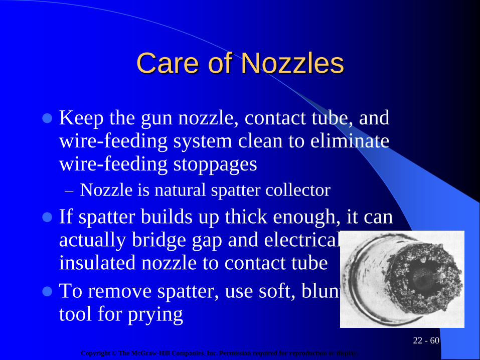
Care of Nozzles
Keep the gun nozzle, contact tube, and wire-feeding system clean to eliminate wire-feeding stoppages
– Nozzle is natural spatter collector
If spatter builds up thick enough, it can actually bridge gap and electrically connect insulated nozzle to contact tube
To remove spatter, use soft, blunt tool for prying
Copyright © The McGraw-Hill Companies, Inc. Permission required for reproduction or display.
22 - 61
Care of Nozzles
Spatter almost falls out by itself if nozzle
kept clean, shiny and smooth
Antispatter compound may be applied to
gun nozzle and contact tube end
Do not clean by tapping or pounding on
solid object
– Bends gun nozzles, damages threads and high
temperature insulation in nozzle can break
22 - 62
Care of Contact Tubes
Transfers welding current to electrode wire
Hole has to be big enough to allow wire with
slight cast to pass through easily
Wire wears hole to oval shape
– Wire slides more easily, but transfer of current not as
good and arcing in tub results
– Spatter flies up into bore and wire slows down because
of friction
– Must be replace; secure tightly in gun and check
periodically for tightness

22 - 63
Care of Wire-Feed Cables
Wire-feed conduit flexible steel tube that
does not stretch
Main source of friction in wire-feed system
Should be kept clean and straight as
possible
– Clean with dry compressed air
Lubricate with dry powdered graphite
reduces friction
Clean every time spool or coil changes
22 - 64
Bird Nesting
Wire coils sideways between wire-feed
cable and drive rolls
Prevent by accurate alignment of wire-feed
cable inlet guide
– Aligned exactly with rollers so wire does not
have to make reverse bend
– Notch in drive rolls must be in perfect
alignment to provide smooth passage for wire
22 - 65
Cleanliness of Base Metal
Clean area thoroughly before welding
Remove all rust, scale, burned edges and
chemical coatings
– Gas producers
– Porosity is result
Intense heat of arc burns away some of the
contaminants
22 - 66
Arc Blow
Arc blown to one side or other by condition of pull
and counter-pull as magnetic field is distorted
– Ionized gases carrying arc from end of electrode wire to
work act as flexible conductor with magnetic field
around it
– When placed in location such as corner of joint or end
of plate, magnetic field distorted and pulls in another
direction
– Magnetic field tries to return to state of equilibrium
Does not occur with a.c. welding arcs
– Forces exerted by magnetic field reversed 120 times per
second thus keeping magnetic field in equilibrium
22 - 67
Connecting Work to Minimize Arc Blow
Suggestions to shorten trial-and-error
process to correct or minimize arc blow
Attach work lead or leads directly on
workpiece if possible
Connect both ends of long, narrow
weldments
Use electrical conductors of proper length
Weld away from work connection
22 - 68
Connecting Work to Minimize Arc Blow
On parts that rotate, use rotating work connection or allow work cable to wind up no more than one or two turns
In making longitudinal welds on cylinders, use two work connections—one on each side of the seam as close as possible to point of starting
If multiple work connections necessary, make sure cables are same size and length and have identical terminals
22 - 69
Connecting Work to Minimize Arc Blow
On multiple-head installations, all heads should weld in same direction and away from work connection
Use individual work circuits on multiple-head installations
Do not place two or more arcs close to one another on weldments that are prone to magnetic disturbance with one arc such as tubes or tanks requiring longitudinal seams
22 - 70
Setting Up Equipment
Constant voltage d.c. power source
Wire-feeding mechanism with controls and spooled or reeled filler wire mounted on fixture
Gas-shielding system consisting of one or more cylinders of compressed gas, pressure-reducing cylinder regulator, flowmeter assembly
Combination gas, water, wire, and cable control assembly and welding gun of correct type and size
Connecting hoses and cables, work lead, and clamp
Face helmet, gloves, sleeves (if necessary), and assortment of hand tools
22 - 71
Assumed Safety Precautions
Welding equipment installed properly
Welding machine in dry location, and no
water on floor of welding booth
Welding booth lighted and ventilated
properly
All connections tight, and all hoses and
leads arranged so they cannot be burned or
damaged
Gas cylinders securely fastened so they
cannot fall over and not part of electrical
22 - 72
Starting Procedure
1. Check power cable connections; connect gun cable to proper welding terminal on welding machine and work cable end connected to proper terminal on welding machine
2. Start welding machine by pressing onbutton or, in case of engine drive, start engine
3. Turn on wire-feed unit
4. Check gas-shielding supply system
5. Check water flow if gun water cooled

22 - 73
Starting Procedure
5. Set wire-feed speed control for type and size of filler wire and for job
6. Voltage rheostat should be set to conform to type and thickness of material being welded, diameter of filler wire, the type of shielding gas, and type of arc
7. Adjust for proper electrode extension beyond contact tube
8. To start arc, touch end of electrode wire to proper place on weld joint, usually just ahead of weld bead, with current shut off; lower helmet and press gun trigger on torch
22 - 74
Shutting Down the Equipment
1. Stop welding and release gun trigger
2. Return feed speed to zero position
3. Close gas outlet valve in top of gas cylinder
4. Squeeze welding gun trigger, hold it down, and bleed gas lines
5. Close gas flowmeter valve until finger-tight
6. Shut off welding machine and wire feeder
7. Hang up welding gun and cable assembly
22 - 75
Starting the Weld
Running start
– Arc started at beginning of weld
– Electrode end put in contact with base metal
– Trigger on torch pressed
– Tends to be too cold at beginning of weld
Scratch start
– Arc struck approximately 1 inch ahead of beginning of
weld
– Arc quickly moved back to starting point of weld,
direction of travel reversed, and weld started
– Arc may also be struck outside of weld area on starting
tab
22 - 76
Finishing the Weld
Arc should be manipulated to reduce penetration
depth and weld pool size when completing weld
bead
– Decreases final shrinkage area
– Reduction accomplished by rapidly increasing speed of
welding for approximately 1 to 2 inches of weld length
– Trigger released, stopping wire feed and interrupting
welding current
Gun trigger can be turned on and off several times
at end of weld to fill crater
22 - 77
Gun Angle
Push angle of 5 to 15 generally employed when welding in flat position
– Take care push angle not changed as end of weld approached
Work angle equal on all sides when welding uniform thicknesses
Welding in horizontal position, point gun upward slightly
Thick-to-thin joints, direct arc toward heavier section
Slight drag angle may help when welding thin sections
22 - 78
Control of Arc
Arc voltage controls penetration, bead
contour, and such defects as undercutting,
porosity and weld discontinuities
Arc should be occasionally noisy for most
applications of spray arcs
22 - 79
Practice Jobs
Practice gas metal arc welding on mild
steel, aluminum, and stainless steel
Specifications given in Job Outline in order
assigned by instructor
Beyond these job, practice other forms of
joints in all positions
– Use various types and sizes of filler wire and
different shielding gases
22 - 80
MIG/MAG Welding of Carbon Steel
Bulk of all welding done on carbon steel
MIG/MAG welding on increase
– Welders find it relatively easy to master
– Consistently produces sound welds at high rate
of speed
22 - 81
Groove Welds: Jobs 22-J1 and J2
Plate up to 1/8" thick may be butt welded
with square edges with root opening of 0 to
1/16"
Heavier plate, 3/16 and 1/4 inch may be
welded without beveling edges if 1/16 to
3/32" opening provided
Bead should be wider than root spacing for
proper fusion
Two passes, one from each side usually
needed
22 - 82
Groove Welds: Jobs 22-J1 and J2
For code welding, plate thicknesses from 3/16 to 1" should be beveled– 60º single- or double-V without root face
recommended
– Root opening of 0 to 1/16" should be maintained
– Wider root openings may be provided for double-V joints
– Single-V grooves backing pass from reverse side generally required
Less distortion when welding from both sides of joint

22 - 83
Groove Welds: Jobs 22-J1 and J2
Open root joint should be run using short
circuit or pulse spray for ferrous metals
Practice 3G using both uphill and downhill
techniques
U-grooves used on plate thicker than 1 inch
– Root spacing between 1/32 and 3/32"
maintained
– Root face of 3/32" or less to assure penetration
– Requires less filler metal than V groove butt
joint
22 - 84
Groove Welds: Jobs 22-J1 and J2
Argon-oxygen mixture containing 1-5% oxygen
recommended for spray arc welding
– Oxygen improves flow of weld metal and reduces
tendency to undercut
Argon with 10% CO2 sometimes used
Carbon dioxide at 100% used by arc not true spray
arc
– Popular for MAG small wire welding
Short arc welding of carbon steel uses mixture of
75% argon and 25% carbon dioxide
22 - 85
Fillet Welds: Jobs 22-J3-J10
Used in T-joints, lap joints, and corner joints
Deposit rate and rate of travel high with deep
penetration
Permits smaller fillet welds than with stick
electrode welding
Position of nozzle and speed of welding important
Welding may be single pass or multipass
– Multipass may be done with stringer or weave beads
Each pass must be cleaned carefully
22 - 86
Inspection and Testing
Copyright © The McGraw-Hill Companies, Inc. Permission required for reproduction or display.
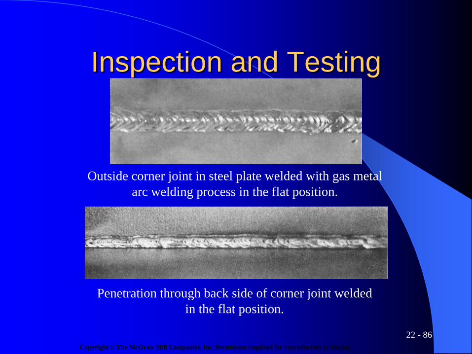
Outside corner joint in steel plate welded with gas metal
arc welding process in the flat position.
Penetration through back side of corner joint welded
in the flat position.
22 - 87
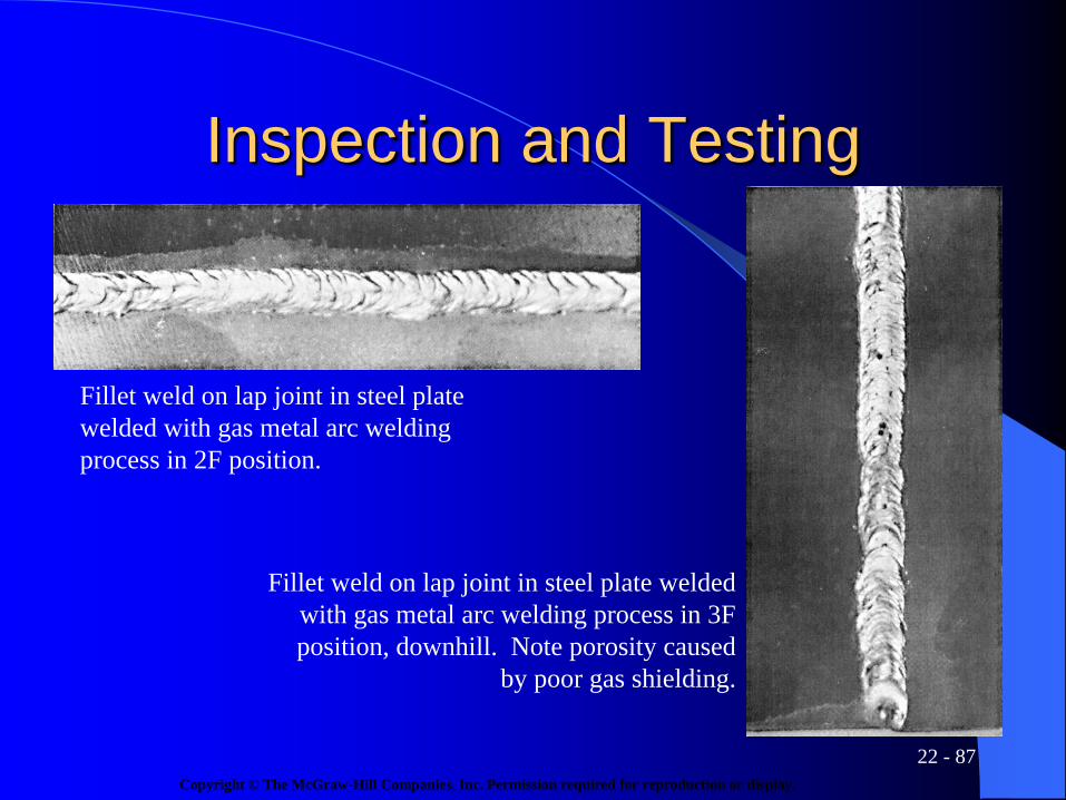
Inspection and Testing
Fillet weld on lap joint in steel plate
welded with gas metal arc welding
process in 2F position.
Copyright © The McGraw-Hill Companies, Inc. Permission required for reproduction or display.
Fillet weld on lap joint in steel plate welded
with gas metal arc welding process in 3F
position, downhill. Note porosity caused
by poor gas shielding.
22 - 88
Inspection and Testing
Copyright © The McGraw-Hill Companies, Inc. Permission required for reproduction or display.
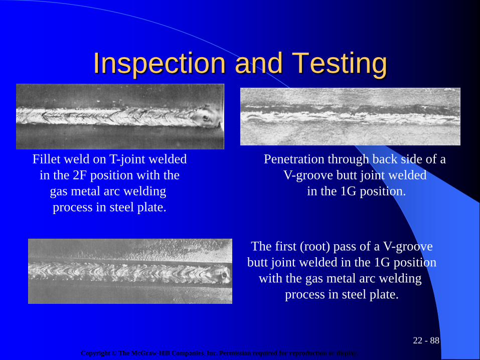
Fillet weld on T-joint welded
in the 2F position with the
gas metal arc welding
process in steel plate.
Penetration through back side of a
V-groove butt joint welded
in the 1G position.
The first (root) pass of a V-groove
butt joint welded in the 1G position
with the gas metal arc welding
process in steel plate.
22 - 89
Fillet and Groove Welding Combination
Project:
Job Qualification Test 1
Purpose
– Ability to read print
– Develop bill of materials
– Thermally cut
– Fit components together
– Tack and weld carbon steel project
Follow instructions found in Fig. 22-26
22 - 90
Fillet and Groove Welding Combination
Project:
Job Qualification Test 1
Inspection and testing (visual inspection only)
– Shall be no cracks or incomplete fusion
– Shall be no incomplete joint penetration in groove welds except as permitted for partial joint penetration groove welds
– Undercut shall not exceed lesser of 10% of base metal thickness or 1/32 inch
– Frequency of porosity shall not exceed one in each 4 inches of weld length, and maximum diameter shall not exceed 3/32 inch
– Welds shall be free from overlap
– Only minimal weld spatter shall be accepted
22 - 91
Fillet and Groove Welding
Combination Project: Job Qualification
Test2
Purpose
– Ability to read print
– Develop bill of materials
– Thermally cut
– Fit components together
– Tack and weld carbon steel project
– Use spray arc mode of metal transfer
– Note on Fig. 22-27
22 - 92
Fillet and Groove Welding
Combination Project: Job Qualification
Test2
Inspection and testing (visual inspection only)
– Shall be no cracks or incomplete fusion
– Shall be no incomplete joint penetration in groove welds except as permitted for partial joint penetration groove welds
– Undercut shall not exceed lesser of 10% of base metal thickness or 1/32 inch
– Frequency of porosity shall not exceed one in each 4 inches of weld length, and the maximum diameter shall not exceed 3/32 inch
– Welds shall be free from overlap
– Only minimal weld spatter shall be accepted
22 - 93
Groove Weld Project: Job Qualification Test 3
Project
– Ability to read print
– Fit components together
– Tack and weld carbon steel unlimited thickness
test plate
– Using spray arc mode of metal transfer
– Instructions in notes in Fig. 22-28
22 - 94
Inspection and Testing
After tacking, have it inspected
After complete welding, use visual inspection and cut specimens for bend testing
Use side bend test procedures and check:
Testing criteria:
– No cracks or incomplete fusion
– No incomplete joint penetration in groove welds except as permitted for partial joint penetration groove welds
22 - 95
Inspection and Testing
Testing criteria (cont.):
– Undercut shall not exceed lesser of 10 percent
of base metal thickness or 1/32 inch
– Frequency of porosity shall not exceed one in
each 4 inches of weld length and maximum
diameter shall not exceed 3/32 inch
– Welds shall be free from overlap
– Only minimal weld spatter shall be accepted

22 - 96
Side Bend Acceptance Criteria as Measured
on Convex Surface of Bend Specimen
No single indication shall exceed 1/8 inch
measured in any direction on surface
Sum of greatest dimensions of all indications on
surface, which exceed 1/32 inch, but are less than
or equal to 1/8 inch, shall not exceed 3/8 inch
Cracks occurring at corner of specimens shall not
be considered unless there definite evidence that
they result from slag inclusions or other internal
discontinuities
22 - 97
MIG Welding of Aluminum Readily joined by welding, brazing, soldering,
adhesive bonding, and mechanical fastening
Lightweight
Alloyed readily with many other metals
Highly ductile and retains ductility at subzero temperatures
High resistance to corrosion, no colored salts, not toxic
Good electrical and thermal conductivity
High reflectivity to both heat and light
Nonsparking and nonmagnetic
22 - 98
MIG Welding of Aluminum
Easy to fabricate
May be given wide variety of mechanical, electrochemical, chemical and paint finishes
Needs high heat input for fusion welding
Aluminum and its alloys rapidly develop oxide film when exposed to air (melting point 3600ºF)
– Must be removed during welding
Removed by fluxes, action of arc in inert gas atmosphere or mechanical and chemical means
22 - 99
MIG Welding of Aluminum
MIG and TIG replaced stick electrode
welding for aluminum and its alloys
– Small percentage still using stick electrodes
Type of joint and position of welding
determines process to used on thicknesses
1/8 inch and under
22 - 100
Factors that Make Gas Metal Arc
Welding Desirable Joining Process for
Aluminum
Cleaning time reduced because there no
flux on weld
Absence of slag in weld pool eliminates
possibility of entrapment
Weld pool highly visible due to absence of
smoke and fumes
Welding can be done in all positions
22 - 101
Joint Preparation
Designed like those for steel
Narrower joint spacing and lower welding currents used
Foreign substances must be removed
– Wiped off or removed by vapor degreasing
– Oxide film removed by chemical and mechanical cleaning methods
Weld as soon as possible before oxide film has chance to form again
Sheared edges can also cause poor quality welds
22 - 102
Shielding Gas
Argon preferred for welding aluminum plate thicknesses up to 1 inch
Plate thicknesses 1-2 inches may use:– Pure argon, mixture of 50% argon and 50% helium, or
mixture of 75% argon and 25% helium
– Helium provides high heat and argon excellent cleaning action
Plate thicknesses from 2-3 inches– Mixture of 50% argon and 50% helium or 25% argon
and 75% helium
Plate thicknesses greater than 3 inches– Mixture of 25% argon and 75% helium
22 - 103
Spray Arc Welding
Weld metal deposited continuously
More arc energy and greater heat provided for
melting filler wire and base material
Helium, helium-argon mixtures and argon used as
shielding gases
– Choice dependent upon type of material, thickness and
welding position
Welding can be done in all positions
GMAW-P very effective when welding aluminum
22 - 104
Out-of-Position Welding
Horizontal position
– Care must be taken to penetrate to root of joint
when welding butt joints and T-joints
– Overheating in any one area causes sagging,
undercutting or melt-through to back of joint
– Weld metal should be directed against upper
plate
– In multipass welding, be sure fusion between
passes
22 - 105
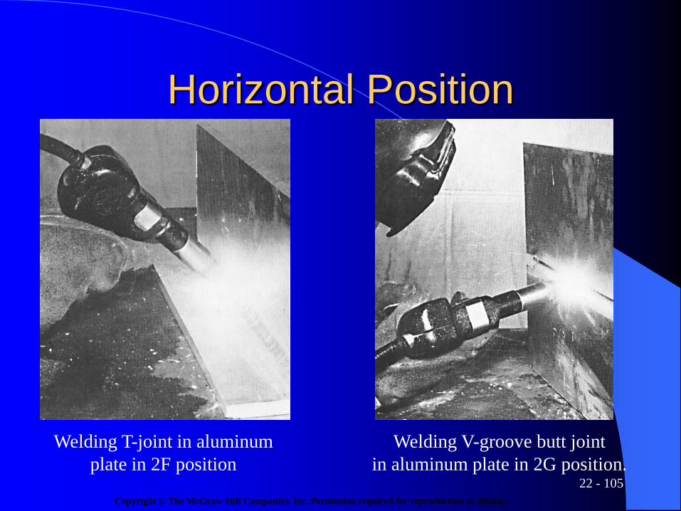
Horizontal Position
Welding T-joint in aluminum
plate in 2F position
Welding V-groove butt joint
in aluminum plate in 2G position.
Copyright © The McGraw-Hill Companies, Inc. Permission required for reproduction or display.
22 - 106
Out-Of-Position Welding
Vertical position
– Travel-up technique on fillet and groove welds
– Do not use too high welding current nor deposit too
large weld bead
– Slight side-to-side motion helpful
Overhead position
– No problem with fillet and groove welds
– Welding current and travel speed lower than flat
position
– Gas flow rate higher because gas has tendency to leave
area
– Somewhat awkward – assume relaxed position as
22 - 107
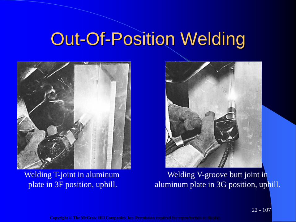
Out-Of-Position Welding
Copyright © The McGraw-Hill Companies, Inc. Permission required for reproduction or display.
Welding V-groove butt joint in
aluminum plate in 3G position, uphill.
Welding T-joint in aluminum
plate in 3F position, uphill.
22 - 108
Butt Joints: Jobs 22-J11 and
J12
Easy to design
Require minimum of base material
Perform better under fatigue loading
Require accurate alignment and edge preparation
Usually necessary to bevel edge on thicknesses of ¼" or more to permit root pass penetration
– On heavier plate, chipping back side and welding back side with one pass
– Sections with different thicknesses should be beveled before welding
22 - 109
Lap Joints: Job 22-J13
More widely used on aluminum alloys than
on other materials
Use double-welded, single-lap joints in
thicknesses of aluminum up to ½"
Require no edge preparation
Easy to fit
Require less jigging than butt joints
22 - 110
T-Joints: Jobs 22-J14-J16
Seldom require edge preparation on material ¼" or
less in thickness
Fully penetrated if weld fused into root of joint
Easily fitted and normally require no back
chipping
Jigging usually quite simple
Better to put small continuous fillet weld on each
side of joint rather than one large weld on one side
Continuous fillet welding recommended over
intermittent welding for longer fatigue life
22 - 111
Edge and Corner Joints
Economical from standpoint of preparation,
base metal used, and welding requirements
Harder to fit up
Prone to fatigue failure
Edges do not require preparation
22 - 112
Inspection and Testing
Inspect carefully for defects
Use same inspection and testing procedures
used previously
Look for surface defects
High quality welds in aluminum can be
produced only if proper welding conditions
and good cleaning procedures been
established and maintained
22 - 113
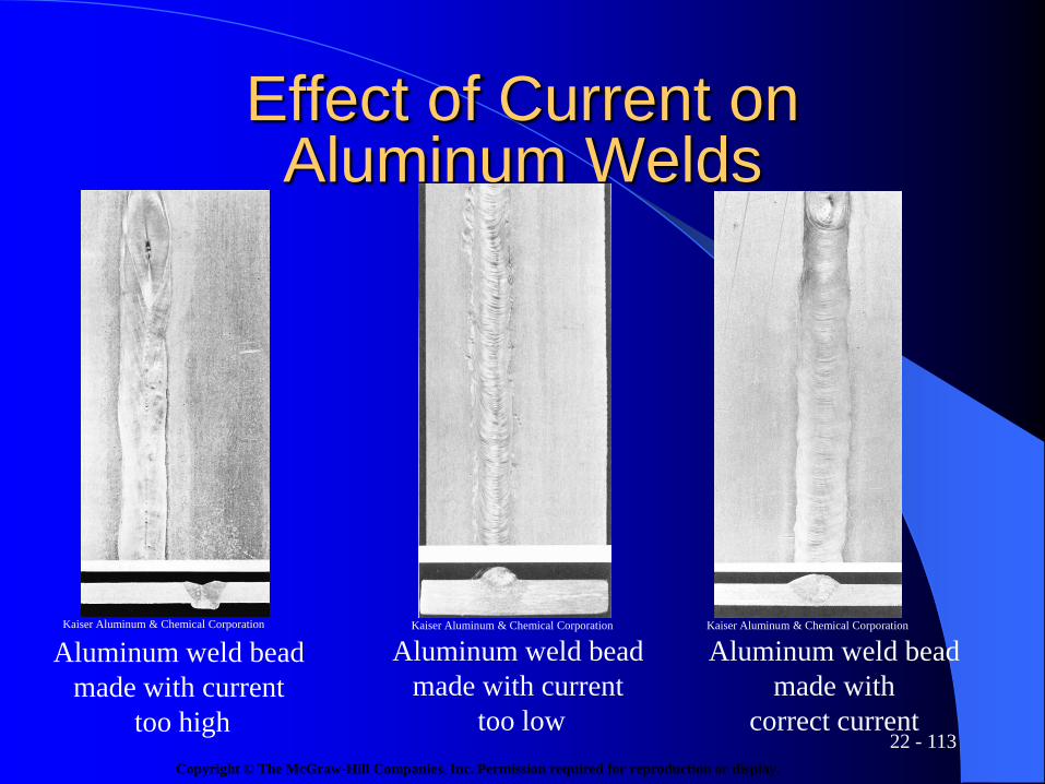
Effect of Current on Aluminum Welds
Copyright © The McGraw-Hill Companies, Inc. Permission required for reproduction or display.
Aluminum weld bead
made with current
too high
Aluminum weld bead
made with current
too low
Aluminum weld bead
made with
correct current
Kaiser Aluminum & Chemical Corporation Kaiser Aluminum & Chemical Corporation Kaiser Aluminum & Chemical Corporation

22 - 114
Main Causes of Cracking in Aluminum Welds
Generally in crater or longitudinal form
Crater cracks
– Cause: arc broken sharply and leaves crater
– Cure: manipulate gun properly
Longitudinal cracks caused by
– Incorrect weld metal composition
– Improper welding procedure
– High stresses imposed during welding by poor joint design or poor jigging
22 - 115
Main Causes of Porosity in Aluminum Welds
Hydrogen in the weld area
Moisture, oil, grease, or heavy oxides in the weld
area
Improper voltage or arc length
Improper or erratic wire feed
Contaminated filler wire (Use as large a diameter
as possible and GMAW-P if lower heat is needed.)
Leaky gun
Contaminated or insufficient shielding gas
22 - 116
Major Causes of Incomplete Fusion
of Weld Metal with Base Metal
Incomplete removal of oxide film before
welding
Unsatisfactory cleaning between passes
Insufficient bevel or back chipping
Improper amperage (WFS) or voltage
22 - 117
Causes of Inadequate Penetration at
Root of Weld and Into Side Walls of
Joint
Low welding current (WFS)
Improper filler metal size
Improper joint preparation
Too fast travel speeds for the selected wire-
feed speed
22 - 118
Causes of Metallic and Nonmetallic
Inclusions in Aluminum Welds
Copper inclusions caused by burn-back of
electrode to contact tube
Metallic inclusions from cleaning weld with
wire brush which leaves bristles in weld
Nonmetallic inclusions from poor cleaning
of base metal
Always use push gun travel angle when
welding aluminum
22 - 119
Groove Weld Project: Job Qualification Test 4
Purpose
– Ability to read print
– Fit components together
– Tack
– Weld aluminum test plates
– Using spray arc mode of metal transfer
Inspection and testing
– Visual inspection
– Perform side bend tests
22 - 120
Copyright © The McGraw-Hill Companies, Inc. Permission required for reproduction or display.
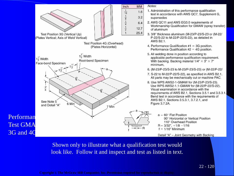
Performance Qualification
Test GMAW Spray Transfer, Aluminum
3G and 4G Positions
AWS SENSE
Shown only to illustrate what a qualification test would
look like. Follow it and inspect and test as listed in text.
22 - 121
MAG Welding of Stainless Steel
Heat and corrosion resistant alloy
– Always contains high percentage of chromium in addition to nickel and manganese
Excellent strength-to-weight ratios
Many alloys possess high degree of ductility
Widely used in products such as tubing, piping, kitchen equipment, ball bearings
Supplied in sheets, strip, plate, shapes, tubing, pipe and wire extrusions
22 - 122
MAG Welding of Stainless Steel
Lower rate of thermal conductivity than carbon steel– Heat retained in weld zone longer
Thermal expansion greater than carbon steel– Causes greater shrinkage stresses and warpage
Has tendency to undercut
All standard forms of joints used in fabrications
Copper backing bars necessary for welding sections up to 1/16" thick
No air must be permitted to reach underside of weld while weld pool solidifying (air weakens it)– If no backing bar, argon should be used as purge gas
shield
22 - 123
Advantages of MAG Welding Stainless Steel
Absence of slag-forming flux reduces cleaning time and makes it possible to observe weld pool
Continuous wire feed permits uninterrupted welding
MAG lends itself to automation
Welding may be performed with short-circuiting, spray, or pulsed spray modes of transfer
22 - 124
Spray Arc Welding
Electrode diameters as large as 3/32" can be used for stainless steel– 1/16" wire used with high current to create spray arc
transfer of metal
DCEP used for most stainless-steel welding
Most common gas: mixture of Ar and 1 to 2% O– Recommended for single-pass welding
Push travel angle should be employed on plate ¼" thick or more
Gun should be moved back and forth in direction of travel and slightly from side to side
22 - 125
Short Arc Welding (GMAW-S)
Requires low current ranging form 20 to 175
amperes; low voltage of 12 to 20 volts, small
diameter wires
Metal transfer occurs when filler wire short
circuits with base metal
Ideally suited for most stainless-steel welding on
thicknesses from 16 gauge to 1/16"
– Also for first pass in which fitup is poor or copper
backing unsuitable
– Very desirable in vertical and overhead positions for
first pass
22 - 126
Short Arc Welding (GMAW-S)
For stainless steel in light gauges, triple
mixture of gas gives good arc stability and
excellent coalescence
– 90% helium, 7 ½% argon and 2 ½% carbon
dioxide
– Produces small heat-affected zone that
eliminates undercutting and reduces distortion
– Does not lower corrosion resistance
– Flow rates must be increased because of lower
density of helium
22 - 127
Pulse Spray Arc (GMAW-P)
Can be done with lower current levels and higher wire-feed speeds
Can be used on all thickness ranges
Spray-type gas: 1 and 2% oxygen with remainder being argon most common
Weld more fluid and flows well because arc on all the time
Spatter reduced on thin base metals as compared to short-circuiting mode of transfer
22 - 128
Hot Cracking
Tendency of some stainless steels
– More welding passes needed
– Stringer beads recommended instead of weave
Reduce contraction stresses and cooling more rapid
Can reduce when welding sections 1 inch or
thicker by preheating to 500ºF
– Also reduce by GMAW-S or P welding
22 - 129
Stainless-Steel Sensitization
Carbide precipitation
– Sensitizing chromium out of individual grains of
austenitic types of stainless steel
– Occurs most readily in 1,200ºF heat range
To reduce situation
– Use GMAW process with its rapid speed and high
deposition rate
– Use stabilized and low carbon grades of stainless steel
– Using proper filler metals such as ER308L which is low
in carbon
22 - 130
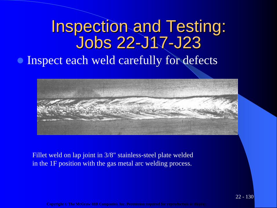
Inspection and Testing: Jobs 22-J17-J23
Inspect each weld carefully for defects
Fillet weld on lap joint in 3/8" stainless-steel plate welded
in the 1F position with the gas metal arc welding process.
Copyright © The McGraw-Hill Companies, Inc. Permission required for reproduction or display.
22 - 131
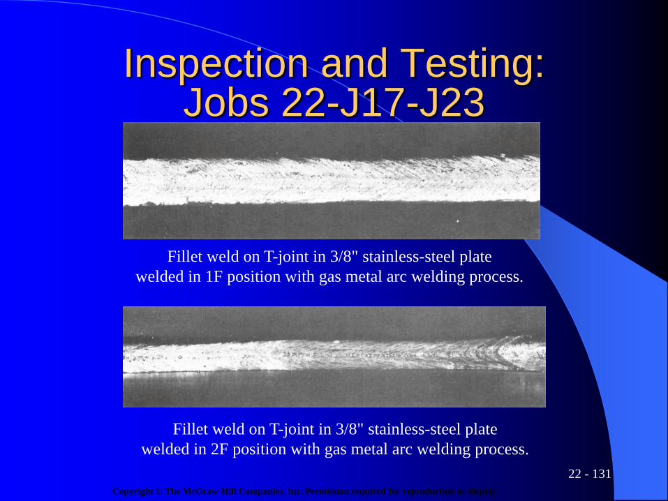
Inspection and Testing: Jobs 22-J17-J23
Fillet weld on T-joint in 3/8" stainless-steel plate
welded in 1F position with gas metal arc welding process.
Fillet weld on T-joint in 3/8" stainless-steel plate
welded in 2F position with gas metal arc welding process.
Copyright © The McGraw-Hill Companies, Inc. Permission required for reproduction or display.
22 - 132
Copper and Its Alloys May be welded successfully by gas metal arc process
Electrolytic copper can be joined by using special techniques, but weldability not good
Various grades of deoxidized copper readily weldable with MIG process– Deoxidized filler wires necessary
Filler wires of approximately matching chemistry used
Argon preferred shielding gas for material 1" and thinner– Flow of 50 cubic feet per hour sufficient
– Heavier material uses 65% and 35% argon
22 - 133
Copper and Its Alloys
Joint design like any other metal
– Steel backup necessary for sheets 1/8" or thinner
Welding currents on high side required
– Preheat not required when welding ¼" or less
Always provide good ventilation when welding copper and its alloys
– Beryllium-copper alloy dangerous
22 - 134
Copper and Its Alloys
GMAW-B
– Variation of GMAW process where B indicates
brazing or just MIG brazing
– Uses silicon-bronze type electrode with inert
shielding with Argon 100% most common
– Main application for coated carbon steel sheet
metal (light gauge)
– Zinc coating applied for corrosion resistance
– Base metal not melted (hence brazing operation)
22 - 135
Nickel and Nickel-Copper Alloys
Can be welded using gas metal arc process
Remove all foreign material in vicinity since susceptible to severe embrittlement and cracking when come in contact with foreign materials
Argon generally preferable for welding up to about 3/8 inch in thickness – Above that thickness, argon-helium mixtures
usually more desirable
Joint preparation like other metals
22 - 136
Magnesium
Silvery white metal, two-thirds weight of aluminum and one-quarter weight of steel
Melting point of 1,204ºF
Strength-to-weight ratio high when compared to steel
Welding techniques like aluminum
– Rate of expansion greater
– Care taken that surface clean before welding
Arc characteristics of helium and argon with magnesium different than with other metals
– Argon recommended in most cases
22 - 137
Titanium
Bright white metal that burns in air
Only element that burns in nitrogen
Melting point of about 3,500ºF
Most important compound titanium dioxide
– Used extensively in welding electrode coatings
Used as stabilizer in stainless steel
22 - 138
Zirconium
Bright gray metal
Melting point above 4,500ºF
Very hard and brittle and readily scratches
glass
Used in hard-facing materials
Often alloyed with iron and aluminum
Argon or helium-argon mixtures used for
gas shielding
139
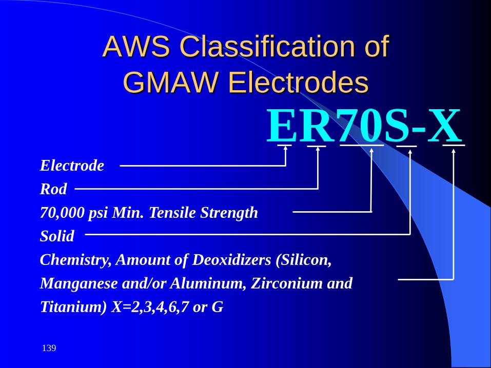
ER70S-XElectrode
Rod
70,000 psi Min. Tensile Strength
Solid
Chemistry, Amount of Deoxidizers (Silicon,
Manganese and/or Aluminum, Zirconium and
Titanium) X=2,3,4,6,7 or G
AWS Classification of
GMAW Electrodes

142
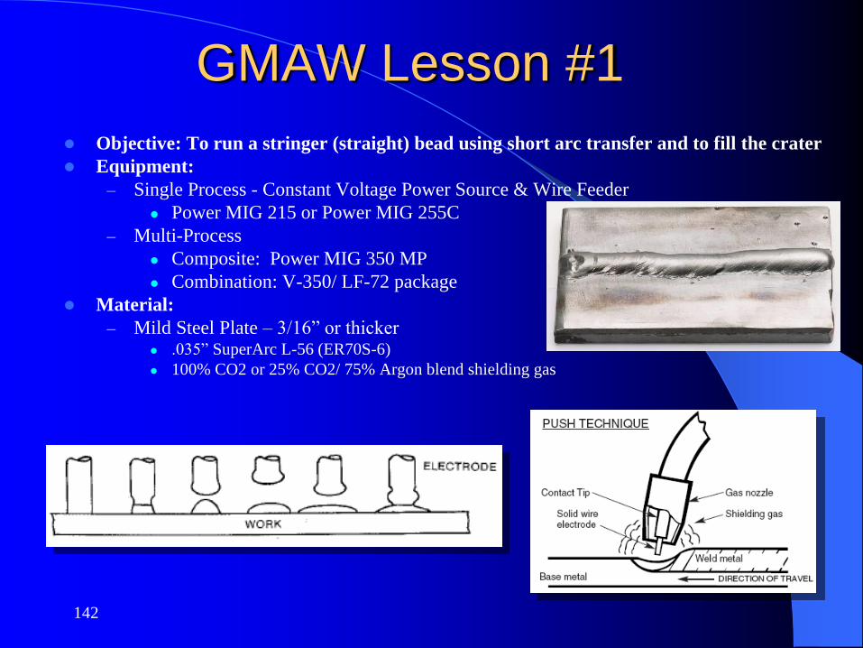
GMAW Lesson #1
Objective: To run a stringer (straight) bead using short arc transfer and to fill the crater
Equipment:
– Single Process - Constant Voltage Power Source & Wire Feeder
Power MIG 215 or Power MIG 255C
– Multi-Process
Composite: Power MIG 350 MP
Combination: V-350/ LF-72 package
Material:
– Mild Steel Plate – 3/16” or thicker .035” SuperArc L-56 (ER70S-6)
100% CO2 or 25% CO2/ 75% Argon blend shielding gas
143
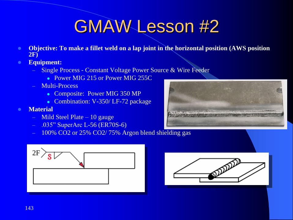
GMAW Lesson #2 Objective: To make a fillet weld on a lap joint in the horizontal position (AWS position
2F)
Equipment:
– Single Process - Constant Voltage Power Source & Wire Feeder
Power MIG 215 or Power MIG 255C
– Multi-Process
Composite: Power MIG 350 MP
Combination: V-350/ LF-72 package
Material
– Mild Steel Plate – 10 gauge
– .035” SuperArc L-56 (ER70S-6)
– 100% CO2 or 25% CO2/ 75% Argon blend shielding gas
2F
144
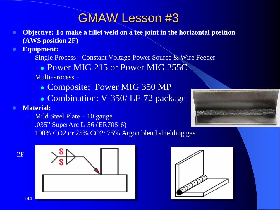
GMAW Lesson #3 Objective: To make a fillet weld on a tee joint in the horizontal position
(AWS position 2F)
Equipment:
– Single Process - Constant Voltage Power Source & Wire Feeder
Power MIG 215 or Power MIG 255C– Multi-Process –
Composite: Power MIG 350 MP
Combination: V-350/ LF-72 package Material:
– Mild Steel Plate – 10 gauge
– .035” SuperArc L-56 (ER70S-6)
– 100% CO2 or 25% CO2/ 75% Argon blend shielding gas
2F
145
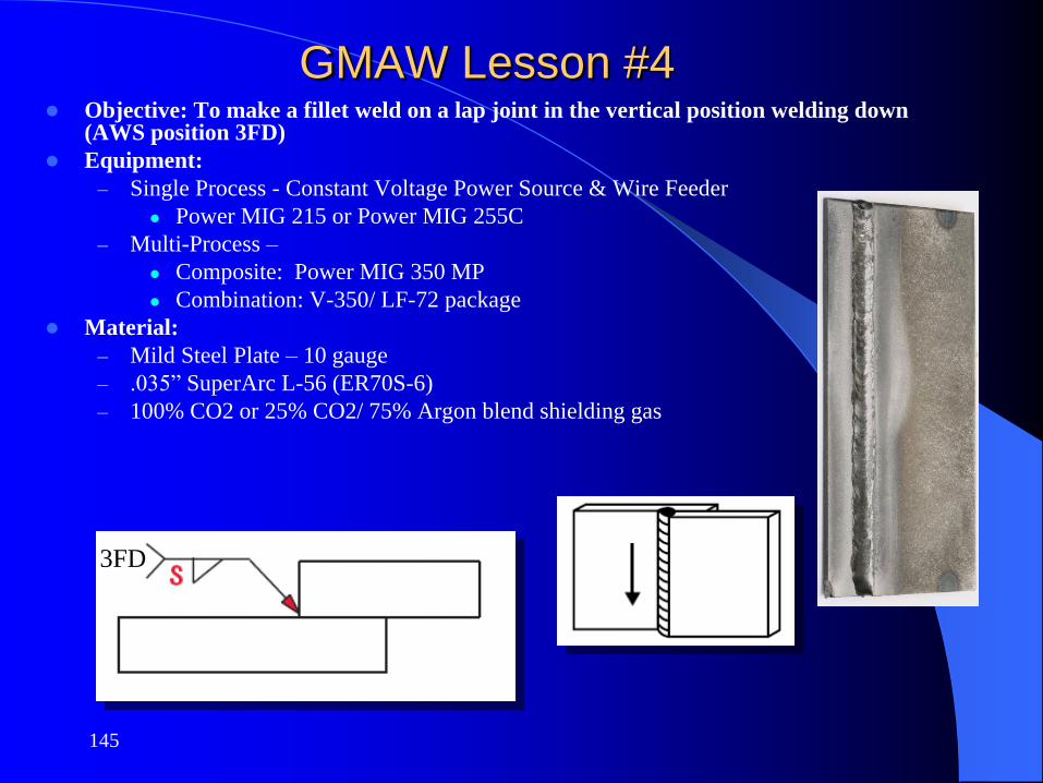
GMAW Lesson #4 Objective: To make a fillet weld on a lap joint in the vertical position welding down
(AWS position 3FD)
Equipment:
– Single Process - Constant Voltage Power Source & Wire Feeder
Power MIG 215 or Power MIG 255C
– Multi-Process –
Composite: Power MIG 350 MP
Combination: V-350/ LF-72 package
Material:
– Mild Steel Plate – 10 gauge
– .035” SuperArc L-56 (ER70S-6)
– 100% CO2 or 25% CO2/ 75% Argon blend shielding gas
3FD
146
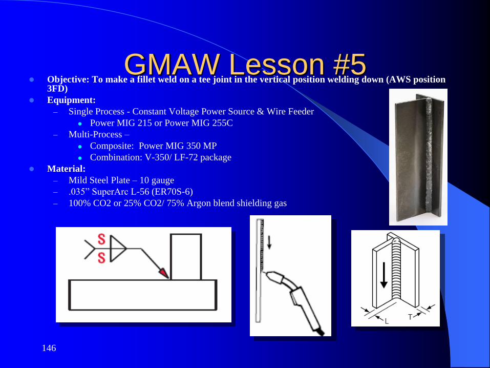
GMAW Lesson #5 Objective: To make a fillet weld on a tee joint in the vertical position welding down (AWS position
3FD)
Equipment:
– Single Process - Constant Voltage Power Source & Wire Feeder
Power MIG 215 or Power MIG 255C
– Multi-Process –
Composite: Power MIG 350 MP
Combination: V-350/ LF-72 package
Material:
– Mild Steel Plate – 10 gauge
– .035” SuperArc L-56 (ER70S-6)
– 100% CO2 or 25% CO2/ 75% Argon blend shielding gas
3FD
147
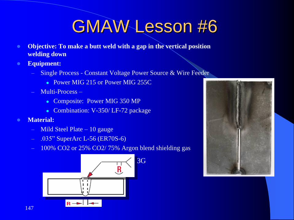
GMAW Lesson #6 Objective: To make a butt weld with a gap in the vertical position
welding down
Equipment:
– Single Process - Constant Voltage Power Source & Wire Feeder
Power MIG 215 or Power MIG 255C
– Multi-Process –
Composite: Power MIG 350 MP
Combination: V-350/ LF-72 package
Material:
– Mild Steel Plate – 10 gauge
– .035” SuperArc L-56 (ER70S-6)
– 100% CO2 or 25% CO2/ 75% Argon blend shielding gas
3G
148
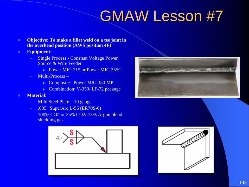
GMAW Lesson #7
Objective: To make a fillet weld on a tee joint in the overhead position (AWS position 4F)
Equipment:
– Single Process - Constant Voltage Power Source & Wire Feeder
Power MIG 215 or Power MIG 255C
– Multi-Process –
Composite: Power MIG 350 MP
Combination: V-350/ LF-72 package
Material:
– Mild Steel Plate – 10 gauge
– .035” SuperArc L-56 (ER70S-6)
– 100% CO2 or 25% CO2/ 75% Argon blend shielding gas
4F
149
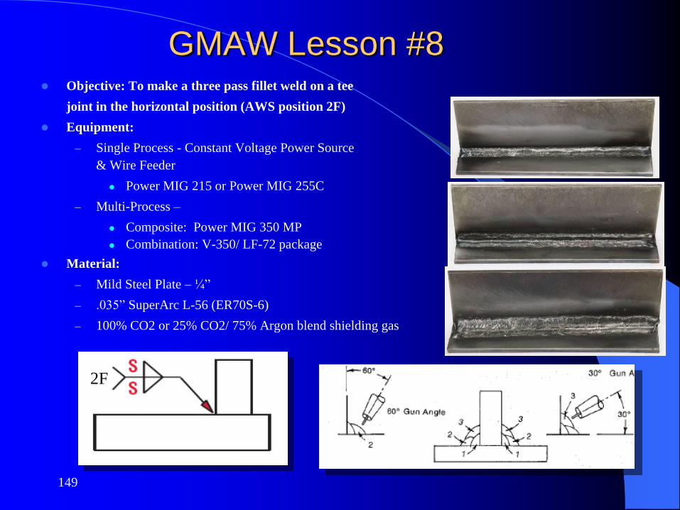
GMAW Lesson #8 Objective: To make a three pass fillet weld on a tee
joint in the horizontal position (AWS position 2F)
Equipment:
– Single Process - Constant Voltage Power Source
& Wire Feeder
Power MIG 215 or Power MIG 255C
– Multi-Process –
Composite: Power MIG 350 MP
Combination: V-350/ LF-72 package
Material:
– Mild Steel Plate – ¼”
– .035” SuperArc L-56 (ER70S-6)
– 100% CO2 or 25% CO2/ 75% Argon blend shielding gas
2F
150
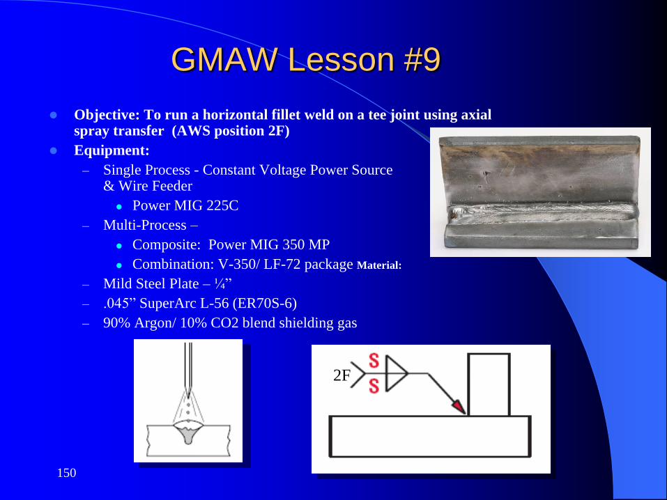
GMAW Lesson #9
Objective: To run a horizontal fillet weld on a tee joint using axial spray transfer (AWS position 2F)
Equipment:
– Single Process - Constant Voltage Power Source & Wire Feeder
Power MIG 225C
– Multi-Process –
Composite: Power MIG 350 MP
Combination: V-350/ LF-72 package Material:
– Mild Steel Plate – ¼”
– .045” SuperArc L-56 (ER70S-6)
– 90% Argon/ 10% CO2 blend shielding gas
2F