datasheet fluke super-thermometer. hubungi pt. siwali swantika 021-45850618
TRANSCRIPT
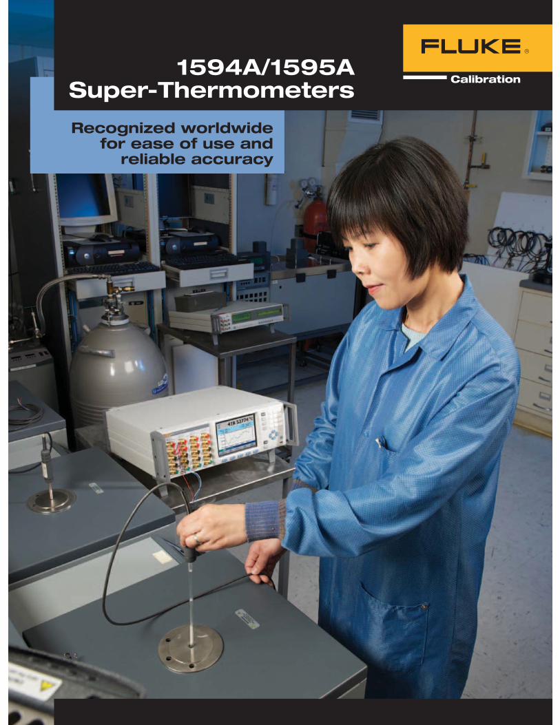
Recognized worldwide for ease of use and
reliable accuracy
1594A/1595A Super-Thermometers
2
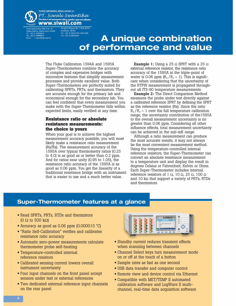
The Fluke Calibration 1594A and 1595A Super-Thermometers combine the accuracy of complex and expensive bridges with innovative features that simplify measurement processes and provide excellent value. Both Super-Thermometers are perfectly suited for calibrating SPRTs, PRTs, and thermistors. They are accurate enough for the primary lab and economical enough for the secondary lab. You can feel confident that every measurement you make with the Super-Thermometer falls within expected limits, easily verified at any time.
Resistance ratio or absolute resistance measurements: the choice is yoursWhen your goal is to achieve the highest measurement accuracy possible, you will most likely make a resistance ratio measurement (Rx/Rs). The measurement accuracy of the 1595A over typical thermometry ratios (0.25 to 4.0) is as good as or better than 0.2 ppm. And for ratios near unity (0.95 to 1.05), the resistance ratio accuracy of the 1595A is as good as 0.06 ppm. You get the linearity of a traditional resistance bridge with an instrument that is easier to use and a much better value.
Super-Thermometer features at a glance
Read SPRTs, PRTs, RTDs and thermistors (0 Ω to 500 kΩ) Accuracy as good as 0.06 ppm (0.000015 °C) “Ratio Self-Calibration” verifies and calibrates resistance ratio accuracy Automatic zero-power measurements calculate thermometer probe self-heating Temperature-controlled internal reference resistors Calibrated sensing current lowers overall instrument uncertainty Four input channels on the front panel accept sensors under test or external references Two dedicated external reference input channels on the rear panel
Standby current reduces transient effects when scanning between channels Channel Select keys turn measurement mode on or off at the touch of a button Sample rates as fast as one second USB data transfer and computer control Remote view and device control via Ethernet Compatible with MET/TEMP II automated calibration software and LogWare II multi-channel, real-time data acquisition software
Example 1: Using a 25 Ω SPRT with a 25 Ω external reference resistor, the resistance ratio accuracy of the 1595A at the triple-point of water is 0.06 ppm (Rx /Rs ≈ 1). This is signifi-cant when considering that the uncertainty of the RTPW measurement is propagated through-out all ITS-90 temperature measurements.
Example 2: The Direct Comparison Method measures the probe under test directly against a calibrated reference SPRT by defining the SPRT as the reference resistor (Rs). Since the ratio Rx /Rs ≈ 1 over the full temperature calibration range, the uncertainty contribution of the1595A to the overall measurement uncertainty is no greater than 0.06 ppm. Considering all other influence effects, total measurement uncertainty can be achieved in the sub-mK range.
Although a ratio measurement can produce the most accurate results, it may not always be the most convenient measurement method. Using the temperature-controlled internal reference resistors, the Super-Thermometer can convert an absolute resistance measurement to a temperature unit and display the result in degrees Celsius or Fahrenheit, Kelvin or Ohms. Each Super-Thermometer includes internal reference resistors of 1 Ω, 10 Ω, 25 Ω, 100 Ω and 10 kΩ that support a variety of PRTs, RTDs and thermistors.
2
A unique combination of performance and value
3
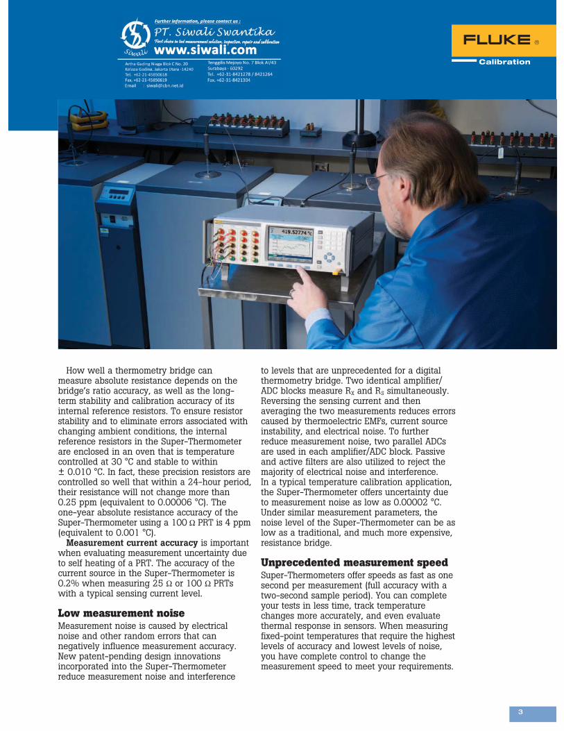
How well a thermometry bridge can measure absolute resistance depends on the bridge’s ratio accuracy, as well as the long-term stability and calibration accuracy of its internal reference resistors. To ensure resistor stability and to eliminate errors associated with changing ambient conditions, the internal reference resistors in the Super-Thermometer are enclosed in an oven that is temperature controlled at 30 °C and stable to within ± 0.010 °C. In fact, these precision resistors are controlled so well that within a 24-hour period, their resistance will not change more than 0.25 ppm (equivalent to 0.00006 °C). The one-year absolute resistance accuracy of the Super-Thermometer using a 100 Ω PRT is 4 ppm (equivalent to 0.001 °C).
Measurement current accuracy is important when evaluating measurement uncertainty due to self heating of a PRT. The accuracy of the current source in the Super-Thermometer is 0.2% when measuring 25 Ω or 100 Ω PRTs with a typical sensing current level.
Low measurement noiseMeasurement noise is caused by electrical noise and other random errors that can negatively influence measurement accuracy. New patent-pending design innovations incorporated into the Super-Thermometer reduce measurement noise and interference
to levels that are unprecedented for a digital thermometry bridge. Two identical amplifier/ADC blocks measure RX and RS simultaneously. Reversing the sensing current and then averaging the two measurements reduces errors caused by thermoelectric EMFs, current source instability, and electrical noise. To further reduce measurement noise, two parallel ADCs are used in each amplifier/ADC block. Passive and active filters are also utilized to reject the majority of electrical noise and interference. In a typical temperature calibration application, the Super-Thermometer offers uncertainty due to measurement noise as low as 0.00002 °C. Under similar measurement parameters, the noise level of the Super-Thermometer can be as low as a traditional, and much more expensive, resistance bridge.
Unprecedented measurement speedSuper-Thermometers offer speeds as fast as one second per measurement (full accuracy with a two-second sample period). You can complete your tests in less time, track temperature changes more accurately, and even evaluate thermal response in sensors. When measuring fixed-point temperatures that require the highest levels of accuracy and lowest levels of noise, you have complete control to change the measurement speed to meet your requirements.
4
Super-Thermometers ensure confidence in every measurement
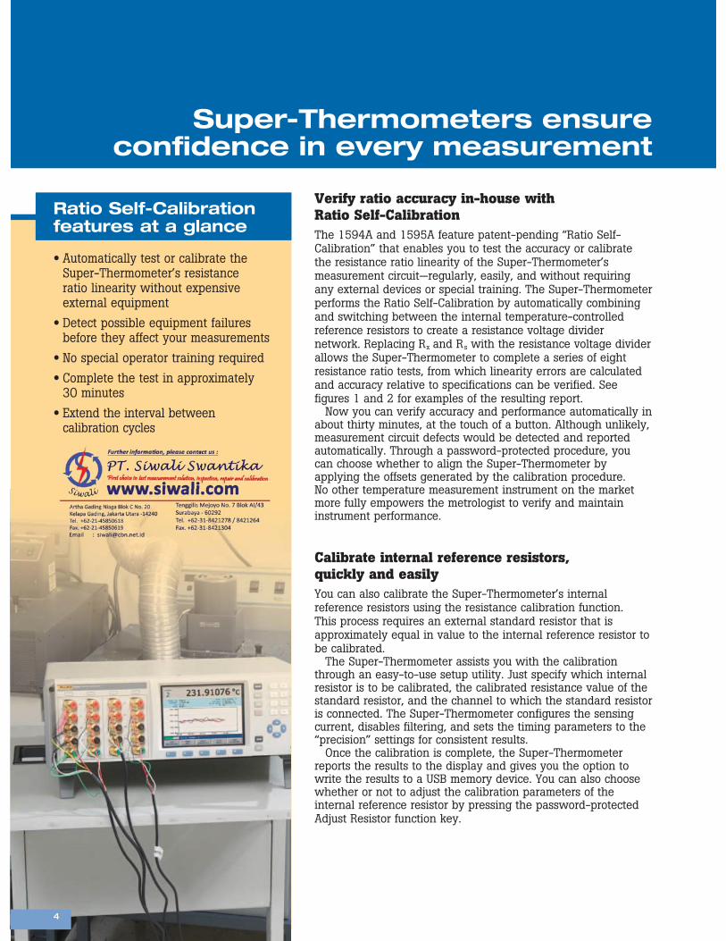
Automatically test or calibrate the Super-Thermometer’s resistance ratio linearity without expensive external equipment Detect possible equipment failures before they affect your measurements No special operator training required Complete the test in approximately 30 minutes Extend the interval between calibration cycles
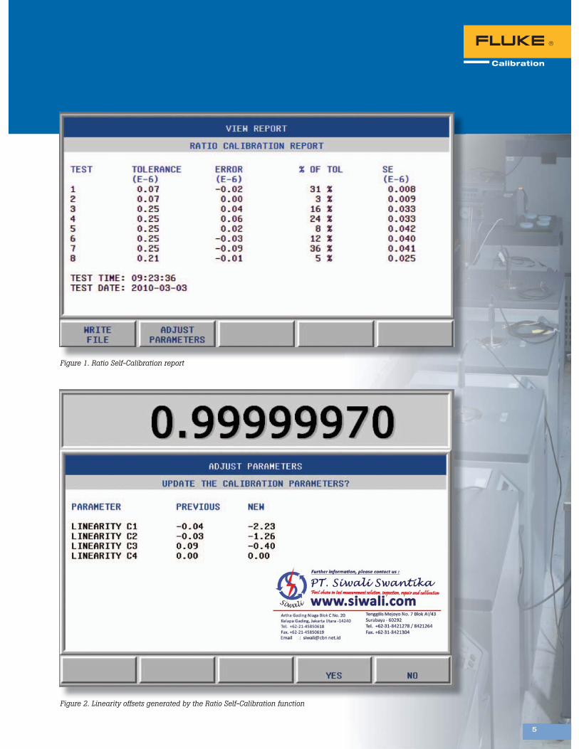
Verify ratio accuracy in-house with Ratio Self-CalibrationThe 1594A and 1595A feature patent-pending “Ratio Self-Calibration” that enables you to test the accuracy or calibrate the resistance ratio linearity of the Super-Thermometer’s measurement circuit—regularly, easily, and without requiring any external devices or special training. The Super-Thermometer performs the Ratio Self-Calibration by automatically combining and switching between the internal temperature-controlled reference resistors to create a resistance voltage divider network. Replacing Rx and Rs with the resistance voltage divider allows the Super-Thermometer to complete a series of eight resistance ratio tests, from which linearity errors are calculated and accuracy relative to specifications can be verified. See figures 1 and 2 for examples of the resulting report.
Now you can verify accuracy and performance automatically in about thirty minutes, at the touch of a button. Although unlikely, measurement circuit defects would be detected and reported automatically. Through a password-protected procedure, you can choose whether to align the Super-Thermometer by applying the offsets generated by the calibration procedure. No other temperature measurement instrument on the market more fully empowers the metrologist to verify and maintain instrument performance.
Calibrate internal reference resistors, quickly and easilyYou can also calibrate the Super-Thermometer’s internal reference resistors using the resistance calibration function. This process requires an external standard resistor that is approximately equal in value to the internal reference resistor to be calibrated.
The Super-Thermometer assists you with the calibration through an easy-to-use setup utility. Just specify which internal resistor is to be calibrated, the calibrated resistance value of the standard resistor, and the channel to which the standard resistor is connected. The Super-Thermometer configures the sensing current, disables filtering, and sets the timing parameters to the “precision” settings for consistent results.
Once the calibration is complete, the Super-Thermometer reports the results to the display and gives you the option to write the results to a USB memory device. You can also choose whether or not to adjust the calibration parameters of the internal reference resistor by pressing the password-protected Adjust Resistor function key.
4
Ratio Self-Calibration features at a glance
5 555
Figure 1. Ratio Self-Calibration report
Figure 2. Linearity offsets generated by the Ratio Self-Calibration function
5
6
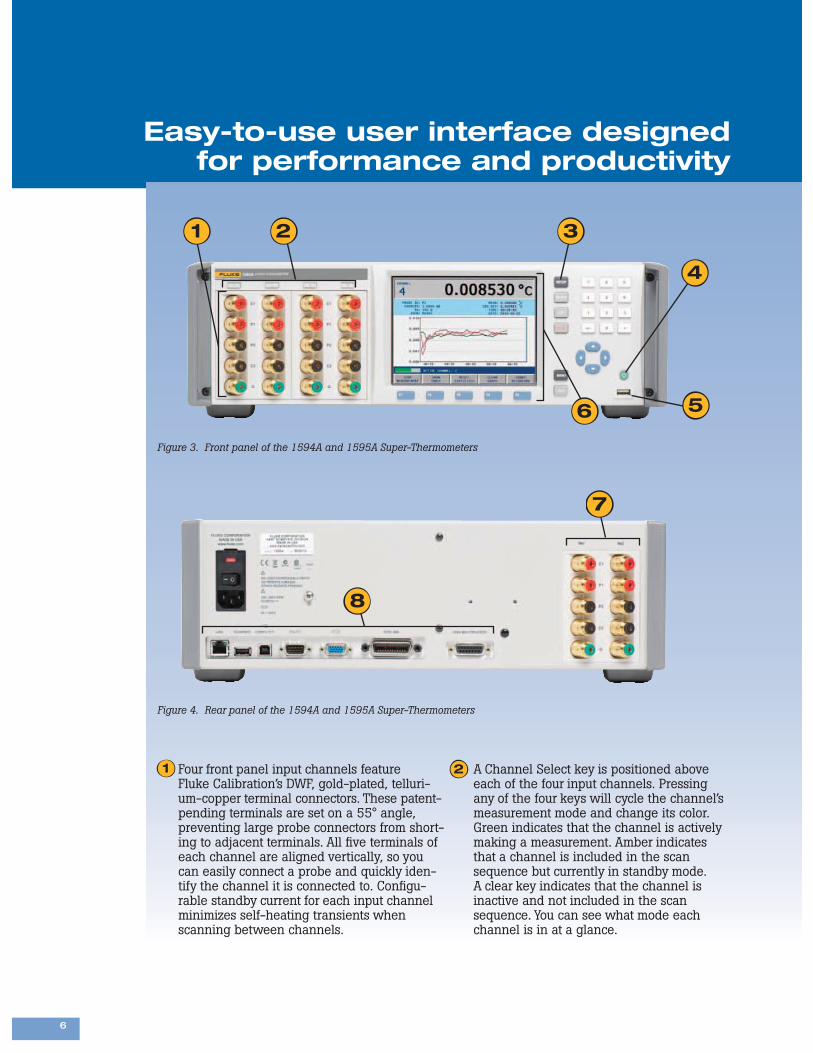
Figure 3. Front panel of the 1594A and 1595A Super-Thermometers
Figure 4. Rear panel of the 1594A and 1595A Super-Thermometers
Easy-to-use user interface designed for performance and productivity
Four front panel input channels feature Fluke Calibration’s DWF, gold-plated, telluri-um-copper terminal connectors. These patent-pending terminals are set on a 55° angle, preventing large probe connectors from short-ing to adjacent terminals. All five terminals of each channel are aligned vertically, so you can easily connect a probe and quickly iden-tify the channel it is connected to. Configu-rable standby current for each input channel minimizes self-heating transients when scanning between channels.
A Channel Select key is positioned above each of the four input channels. Pressing any of the four keys will cycle the channel’s measurement mode and change its color. Green indicates that the channel is actively making a measurement. Amber indicates that a channel is included in the scan sequence but currently in standby mode. A clear key indicates that the channel is inactive and not included in the scan sequence. You can see what mode each channel is in at a glance.
7
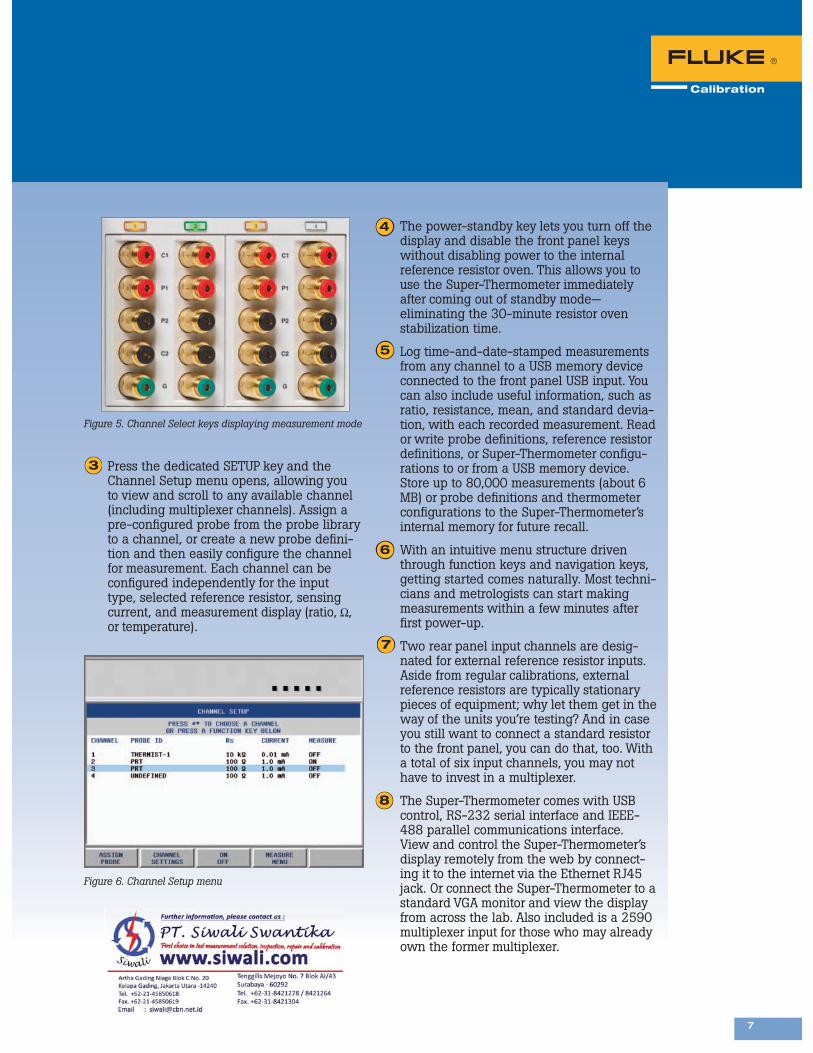
Press the dedicated SETUP key and the Channel Setup menu opens, allowing you to view and scroll to any available channel (including multiplexer channels). Assign a pre-configured probe from the probe library to a channel, or create a new probe defini-tion and then easily configure the channel for measurement. Each channel can be configured independently for the input type, selected reference resistor, sensing current, and measurement display (ratio, Ω, or temperature).
Figure 5. Channel Select keys displaying measurement mode
Figure 6. Channel Setup menu
The power-standby key lets you turn off the display and disable the front panel keys without disabling power to the internal reference resistor oven. This allows you to use the Super-Thermometer immediately after coming out of standby mode— eliminating the 30-minute resistor oven stabilization time.
Log time-and-date-stamped measurements from any channel to a USB memory device connected to the front panel USB input. You can also include useful information, such as ratio, resistance, mean, and standard devia-tion, with each recorded measurement. Read or write probe definitions, reference resistor definitions, or Super-Thermometer configu-rations to or from a USB memory device. Store up to 80,000 measurements (about 6 MB) or probe definitions and thermometer configurations to the Super-Thermometer’s internal memory for future recall.
With an intuitive menu structure driven through function keys and navigation keys, getting started comes naturally. Most techni-cians and metrologists can start making measurements within a few minutes after first power-up.
Two rear panel input channels are desig-nated for external reference resistor inputs. Aside from regular calibrations, external reference resistors are typically stationary pieces of equipment; why let them get in the way of the units you’re testing? And in case you still want to connect a standard resistor to the front panel, you can do that, too. With a total of six input channels, you may not have to invest in a multiplexer.
The Super-Thermometer comes with USB control, RS-232 serial interface and IEEE-488 parallel communications interface. View and control the Super-Thermometer’s display remotely from the web by connect-ing it to the internet via the Ethernet RJ45 jack. Or connect the Super-Thermometer to a standard VGA monitor and view the display from across the lab. Also included is a 2590 multiplexer input for those who may already own the former multiplexer.
8
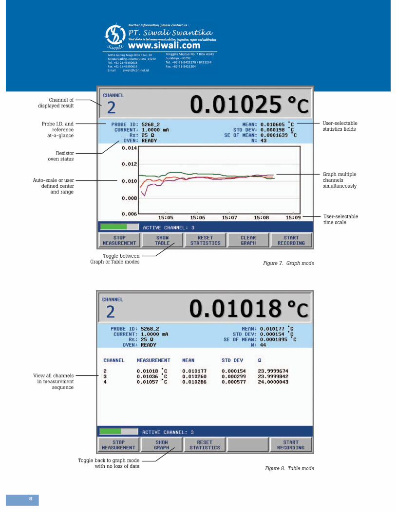
Channel of displayed result
User-selectable statistics fields
Graph multiple channels simultaneously
User-selectable time scale
Probe I.D. and reference
at-a-glance
Auto-scale or user defined center
and range
Resistor oven status
View all channels in measurement
sequence
Toggle between Graph or Table modes
Toggle back to graph mode with no loss of data
Figure 7. Graph mode
Figure 8. Table mode
9
Zero-power function calculates the effects of self-heatingWhen current is passed through a PRT sensor, power is dissipated by the sensing element, causing the sensor to self-heat. That introduces a small temperature error into the measurement. The error can be estimated by measuring the resistance of the sensor at a given temperature with two different sensing current power levels: nominal current and “double-power” (nominal current × 1.4142). Through linear extrapolation to “zero-power,” the resistance value of the sensor can then be estimated as if no current were applied to the sensing element. The temperature error due to self-heating can then be effectively eliminated from the measurement.
Computing a zero-power measurement manually can be time consuming and subject to calculation errors. The Super-Thermometer’s Zero-Power Measurement function sets current levels and collects measurement data automatically, calculating the zero-power measurement for you. User-adjustable settings give you full control of the process by allowing you to set parameters such as settle time, measure time, and record result.
View key measurement data in graphic or table formats, from multiple channels—simultaneouslySuppose you want to see the results of more than one channel simultaneously. The Super-Thermometer includes two measurement viewing modes—graph and table view modes. Select graph mode to graph a single channel or multiple channels simultaneously; set the duration of the graphing window; select automatic centering or enter a fixed value for the vertical center; select automatic scaling; or enter a fixed value for the vertical span. Configure the graph however you like to fit your application. In table mode, the measured value, mean and standard deviation for all channels are displayed simultaneously in a numeric table format. Simply press the function key to toggle between the graph and table views.
Why does a Super-Thermometer out-perform a resistance bridge?
With the 1595A’s resistance ratio accuracy of 0.06 ppm at ratios near 1:1 and accuracy of 0.2 ppm up to ratios of 4:1, a marginal improvement in performance over a limited resistance measurement range doesn’t justify the high price tag of a traditional bridge—especially when considering all of the time-saving, performance-verifying, and self-calibrating features included with the Super-Thermometer. A typical resistance bridge only measures resistance ratio and leaves the temperature conversion up to you. The Super-Thermometer allows you to display your measurement in ratio (RX /RS), Ω, °C, °F, or K without requiring software and a PC to complete the conversion. And don’t forget about the graphing capability of the Super-Thermometer that allows you to view your measurement results from multiple channels simultaneously. An LED display just doesn’t measure up. Assuring the accuracy and performance of a thermometry bridge requires regular testing by specially trained technicians using costly external equipment. Alternatively, a bridge can be serviced out-of-house but at the cost of down-time and work-flow interruption. Ratio Self-Calibration gives the Super-Thermometer the advantage of being able to test its accuracy in-house—regularly, easily, and without the need of external equipment or specialized training. The Super-Thermometer accurately measures resistance ranging from 0 Ω to 500 kΩ, supporting SPRTs, HTSPRTs, PRTs, and almost all thermistors. The resistance measurement range of a typical bridge is inadequate to support all of these precision sensor types and is especially limited when it comes to measuring thermistors. The Super-Thermometer accurately measures resistance ratios up to 10:1. Some bridges are only capable of measuring ratios of 3:1, limiting the types of sensors that can be measured or requiring additional reference resistors to cover a wider temperature range. A bridge can require as much as 20 seconds to achieve full accuracy, whereas the Super-Thermometer’s sample rate to achieve full accuracy is only two seconds. Sample rates as fast as one second are possible, enabling you to check the response time of a sensor or track changes in temperature more accurately.
9
10 101
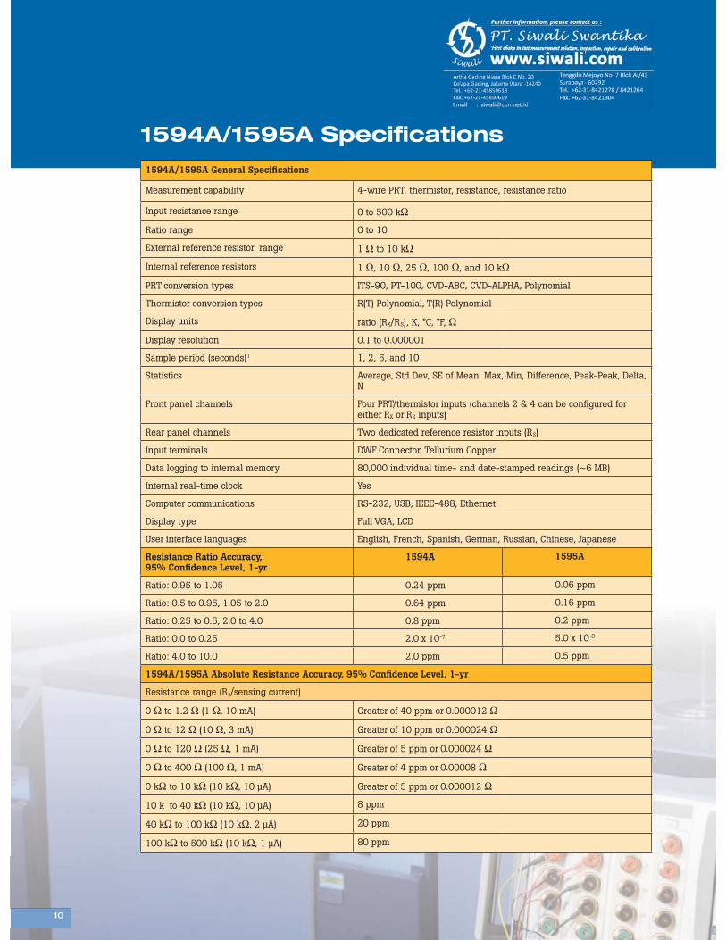
1594A/1595A General Specifications
Measurement capability 4-wire PRT, thermistor, resistance, resistance ratio
Input resistance range 0 to 500 kΩ
Ratio range 0 to 10
External reference resistor range 1 Ω to 10 kΩ
Internal reference resistors 1 Ω, 10 Ω, 25 Ω, 100 Ω, and 10 kΩ
PRT conversion types ITS-90, PT-100, CVD-ABC, CVD-ALPHA, Polynomial
Thermistor conversion types R(T) Polynomial, T(R) Polynomial
Display units ratio (RX/RS), K, °C, °F, Ω
Display resolution 0.1 to 0.000001
Sample period (seconds)1 1, 2, 5, and 10
Statistics Average, Std Dev, SE of Mean, Max, Min, Difference, Peak-Peak, Delta, N
Front panel channels Four PRT/thermistor inputs (channels 2 & 4 can be configured for either RX or RS inputs)
Rear panel channels Two dedicated reference resistor inputs (RS)
Input terminals DWF Connector, Tellurium Copper
Data logging to internal memory 80,000 individual time- and date-stamped readings (~6 MB)
Internal real-time clock Yes
Computer communications RS-232, USB, IEEE-488, Ethernet
Display type Full VGA, LCD
User interface languages English, French, Spanish, German, Russian, Chinese, Japanese
Resistance Ratio Accuracy, 95% Confidence Level, 1-yr
1594A 1595A
Ratio: 0.95 to 1.05 0.24 ppm 0.06 ppm
Ratio: 0.5 to 0.95, 1.05 to 2.0 0.64 ppm 0.16 ppm
Ratio: 0.25 to 0.5, 2.0 to 4.0 0.8 ppm 0.2 ppm
Ratio: 0.0 to 0.25 2.0 x 10⁻⁷ 5.0 x 10⁻⁸
Ratio: 4.0 to 10.0 2.0 ppm 0.5 ppm
1594A/1595A Absolute Resistance Accuracy, 95% Confidence Level, 1-yr
Resistance range (Rs/sensing current)
0 Ω to 1.2 Ω (1 Ω, 10 mA) Greater of 40 ppm or 0.000012 Ω
0 Ω to 12 Ω (10 Ω, 3 mA) Greater of 10 ppm or 0.000024 Ω
0 Ω to 120 Ω (25 Ω, 1 mA) Greater of 5 ppm or 0.000024 Ω
0 Ω to 400 Ω (100 Ω, 1 mA) Greater of 4 ppm or 0.00008 Ω
0 kΩ to 10 kΩ (10 kΩ, 10 μA) Greater of 5 ppm or 0.000012 Ω
10 k to 40 kΩ (10 kΩ, 10 μA) 8 ppm
40 kΩ to 100 kΩ (10 kΩ, 2 μA) 20 ppm
100 kΩ to 500 kΩ (10 kΩ, 1 μA) 80 ppm
1594A/1595A Specifications
10
11 11111111111111111
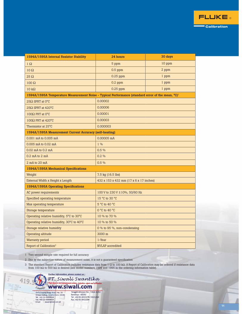
1594A/1595A Internal Resistor Stability 24 hours 30 days
1 Ω 5 ppm 10 ppm
10 Ω 0.5 ppm 2 ppm
25 Ω 0.25 ppm 1 ppm
100 Ω 0.2 ppm 1 ppm
10 kΩ 0.25 ppm 1 ppm
1594A/1595A Temperature Measurement Noise - Typical Performance (standard error of the mean, °C)2
25Ω SPRT at 0°C 0.00002
25Ω SPRT at 420°C 0.00006
100Ω PRT at 0°C 0.00001
100Ω PRT at 420°C 0.00003
Thermistor at 25°C 0.000003
1594A/1595A Measurement Current Accuracy (self-heating)
0.001 mA to 0.005 mA 0.00005 mA
0.005 mA to 0.02 mA 1 %
0.02 mA to 0.2 mA 0.5 %
0.2 mA to 2 mA 0.2 %
2 mA to 20 mA 0.5 %
1594A/1595A Mechanical Specifications
Weight 7.5 kg (16.5 lbs)
External Width x Height x Length 432 x 153 x 432 mm (17 x 6 x 17 inches)
1594A/1595A Operating Specifications
AC power requirements 100 V to 230 V ±10%, 50/60 Hz
Specified operating temperature 15 °C to 30 °C
Max operating temperature 5 °C to 40 °C
Storage temperature 0 °C to 40 °C
Operating relative humidity, 5°C to 30°C 10 % to 70 %
Operating relative humidity, 30°C to 40°C 10 % to 50 %
Storage relative humidity 0 % to 95 %, non-condensing
Operating altitude 3000 m
Warranty period 1-Year
Report of Calibration3 NVLAP accredited
1 Two second sample rate required for full accuracy
2 Due to the subjective nature of measurement noise, it is not a guaranteed specification
3 The standard Report of Calibration includes resistance data from 1 Ω to 100 kΩ. A Report of Calibration may be ordered if resistance data from 100 kΩ to 500 kΩ is desired (see model numbers 1994 and 1995 in the ordering information table).
11
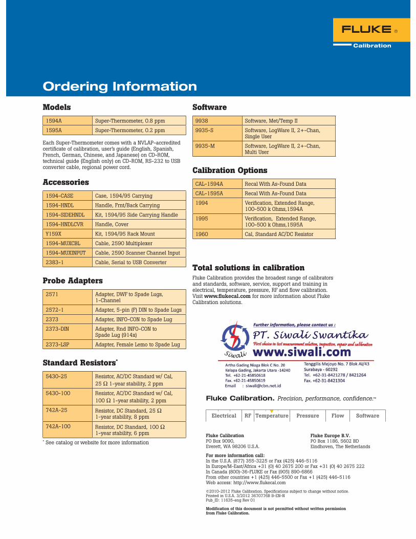
Models1594A Super-Thermometer, 0.8 ppm
1595A Super-Thermometer, 0.2 ppm Each Super-Thermometer comes with a NVLAP-accredited certificate of calibration, user’s guide (English, Spanish, French, German, Chinese, and Japanese) on CD-ROM, technical guide (English only) on CD-ROM, RS-232 to USB converter cable, regional power cord.
Accessories1594-CASE Case, 1594/95 Carrying
1594-HNDL Handle, Frnt/Back Carrying
1594-SIDEHNDL Kit, 1594/95 Side Carrying Handle
1594-HNDLCVR Handle, Cover
Y159X Kit, 1594/95 Rack Mount
1594-MUXCBL Cable, 2590 Multiplexer
1594-MUXINPUT Cable, 2590 Scanner Channel Input
2383-1 Cable, Serial to USB Converter
Probe Adapters2571 Adapter, DWF to Spade Lugs,
1-Channel
2572-1 Adapter, 5-pin (F) DIN to Spade Lugs
2373 Adapter, INFO-CON to Spade Lug
2373-DIN Adapter, Rnd INFO-CON to Spade Lug (914x)
2373-LSP Adapter, Female Lemo to Spade Lug
Standard Resistors*
5430-25 Resistor, AC/DC Standard w/ Cal, 25 Ω 1-year stability, 2 ppm
5430-100 Resistor, AC/DC Standard w/ Cal, 100 Ω 1-year stability, 2 ppm
742A-25 Resistor, DC Standard, 25 Ω 1-year stability, 8 ppm
742A-100 Resistor, DC Standard, 100 Ω 1-year stability, 6 ppm
* See catalog or website for more information
Software9938 Software, Met/Temp II
9935-S Software, LogWare II, 2+-Chan, Single User
9935-M Software, LogWare II, 2+-Chan, Multi User
Calibration OptionsCAL-1594A Recal With As-Found Data
CAL-1595A Recal With As-Found Data
1994 Verification, Extended Range, 100-500 k Ohms,1594A
1995 Verification, Extended Range, 100-500 k Ohms,1595A
1960 Cal, Standard AC/DC Resistor
Total solutions in calibrationFluke Calibration provides the broadest range of calibrators and standards, software, service, support and training in electrical, temperature, pressure, RF and flow calibration.Visit www.flukecal.com for more information about Fluke Calibration solutions.
Ordering Information
Fluke Calibration PO Box 9090, Everett, WA 98206 U.S.A.
Fluke Europe B.V. PO Box 1186, 5602 BD Eindhoven, The Netherlands
For more information call: In the U.S.A. (877) 355-3225 or Fax (425) 446-5116 In Europe/M-East/Africa +31 (0) 40 2675 200 or Fax +31 (0) 40 2675 222 In Canada (800)-36-FLUKE or Fax (905) 890-6866 From other countries +1 (425) 446-5500 or Fax +1 (425) 446-5116 Web access: http://www.flukecal.com
©2010-2012 Fluke Calibration. Specifications subject to change without notice. Printed in U.S.A. 3/2012 3670776B B-EN-N Pub_ID: 11635-eng Rev 01
Modification of this document is not permitted without written permission from Fluke Calibration.
Fluke Calibration. Precision, performance, confidence.™