ahmad fazlizan1*, wan khairul muzammil2, mohd azlan ... · 53 u niversiti p utra m alaysia v s i s...
TRANSCRIPT
UNIVERSITI PUTRA MALAYSIA 53Alam Cipta Vol 12 (Special Issue 1) Sept 2019: Energising Green Building
SKEWED WIND FLOWS ENERGY EXPLOITATION IN BUILT ENVIRONMENT
Ahmad Fazlizan1*, Wan Khairul Muzammil2, Mohd Azlan Ismail2, Mohd Fadhli Ramlee1 and Adnan Ibrahim1
1 Solar Energy Research Institute (SERI), Universiti Kebangsaan Malaysia, 43600 Bangi, Selangor, Malaysia,
2Energy Research Unit, Universiti Malaysia Sabah, Jln. UMS, 88400, Kota Kinabalu, Sabah, Malaysia
* Corresponding author:[email protected]
ABSTRACT
Currently the available wind energy devices, either the horizontal or vertical axis wind turbines, are designed to operate in orthogonal wind flows to generate power. However, in an urban environment, the vertical axis wind turbine is thought to be better suited for building integrated applications due to its durability and better performance in skewed and turbulent flows compared to the more common horizontal axis wind turbine. Application of wind turbines in skewed flow is a subject of increasing interest due to the improved power output of turbines in this wind condition. Skewed flow in the built environment can be referred to as the deflected wind vector at the roofs or edges of buildings that is not horizontal. Therefore, there exists a potential for better diffusion of renewable energy in the urban built environment, especially in the implementation of vertical axis wind turbines on buildings. This paper provides a critical review of the skewed wind flow phenomena, the physical characteristics of the interaction between the skewed flow with the vertical rotor, and the state-of-the-art studies of wind energy devices in skewed flow, especially in the built environment.
Keywords: : Building integrated wind turbine, On-site power generation, Skewed wind flow, Urban energy, Wind energy
1. INTRODUCTION
Developments on small wind turbines for urban areas have gained much attention due to the rising concern in global energy issues. Wind energy is recognized as a potential source of free, clean and inexhaustible energy, especially for use in urban cities where it is urged to place wind turbines closer to populated areas due to the decreasing number of economic sites (Fazlizan, Chong, Yip, Hew, and Poh, 2015; Wagner, Bareiß, and Guidati, 1996). A wind turbine is a device that converts energy from the wind into electrical power that can be used for various applications. Wind farms use large horizontal axis wind turbines (HAWTs) with long blades. These larger wind turbines generate noise and vibration that are not suitable for urban use. In recent years, small vertical axis wind turbines (VAWTs) have been employed in urban areas for local off-grid applications.
It is widely known that the lower efficiency of the VAWT compared to the HAWT is due to the highly unsteady operating conditions of the VAWT at all wind speeds caused by the periodic variation of the rotor and the direction of the apparent wind velocity perceived by the blades (Brahimi, Allet, and Paraschivoiu, 1995). Moreover, as the VAWT rotates, the interactions between wakes shed by the blades rotating in the upwind and downwind regions of the rotor causes dynamic and reliability issues in which the blades have to go through a dynamic stall in every revolution (Amet, Maître, Pellone, and Achard, 2009; Simão Ferreira, van Zuijlen, Bijl, van Bussel, and van Kuik, 2010). Intrinsically, the understanding of the aerodynamic phenomena manifested in VAWTs presents challenging tasks for researchers to thoroughly
Alam Cipta Vol 12 (Special Issue 1) Sept 2019: Energising Green BuildingUNIVERSITI PUTRA MALAYSIA 54
understand the complex fluid mechanics of such devices to estimate their performances (Almohammadi, Ingham, Ma, and Pourkashan, 2013; Daróczy, Janiga, Petrasch, Webner, and Thévenin, 2015; Howell, Qin, Edwards, and Durrani, 2010; Salvadore, Bernardini, and Botti, 2013). Furthermore, new concepts of vertical axis wind energy devices are being introduced to overcome the disadvantages of the conventional design of VAWTs. Some of these wind turbine concepts are being adopted in the design of the building (Meinhold, 2010; Sharpe and Proven, 2010) or mounted on top of a building for maximum exploitation of wind energy (Wong et al., 2014).
The complex nature of urban winds requires wind turbines that are designed to receive the wind from various directions. Moreover, urban winds are erratic, insubstantial and inconsistent due to the many obstacles (e.g. buildings and other obstructions), creating blockages that can reduce wind turbine performances (Abohela, Hamza, and Dudek, 2013). Hence, necessitating wind turbines with excellent self-starting characteristics (Drew, Barlow, and Cockerill, 2013). For a wind energy generation system to be installed in urban areas, several factors need to be considered, i.e. blade failures, noise levels, visual impacts, structural issues, and electromagnetic interference (Knight, 2004; Möllerström, Ottermo, Hylander, and Bernhoff, 2015; Oppenheim, Owen, and White, 2004). Recent investigations on Darrieus vertical axis wind turbines, however, showed that in some cases the behavior of the rotors performed better than a horizontal axis wind turbine in misaligned flow conditions (airflow parallel to the vertical axis of the rotor), though this varies on the design and geometry of the turbine rotor (Mertens, van Kuik, and van Bussel, 2003b, 2003a; Simão Ferreira, van Bussel, and van Kuik, 2006; Simão Ferreira, Van Bussel, and Van Kuik, 2006).
2. SKEWED WIND FLOW IN BUILT ENVIRONMENT
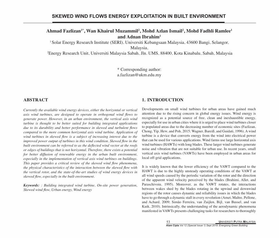
Diffusion of wind energy technology, in particular, small vertical axis wind turbines can effectively be exploited for on-site power generation in the built environment. Theoretically, small wind turbines can be placed on top of buildings to harness a larger potential of wind energy due to the higher zone of wind profile, which is usually exploited by a large horizontal axis wind turbine (Figure 1). The atmospheric boundary layer is the lowest part of the atmosphere that contains most atmospheric gases and humidity (Pandolfi et al., 2013). From a climatological viewpoint, the urban atmosphere has been considered as a boundary layer over a fully rough wall which consists of several layers, including a roughness sublayer and an inertial sublayer (Rotach et al., 2005). Within the inertial sublayer, vertical profiles of environmental
variables such as velocity have been known to satisfy the similarity theory characterised by several aerodynamic parameters including the roughness length and displacement height, which depend on urban geometry (Rahmat, Hagishima, and Ikegaya, 2016). The accurate estimation of aerodynamic parameters of rough urban surfaces, roughness length and displacement height is important for prediction of airflow, dispersion of pollutants, and other atmospheric phenomena (Zaki, Hagishima, Tanimoto, Mohammad, and Razak, 2014). These parameters directly affect the wind flow patterns in the respective area, which alter the surrounding wind environment. The wind profile in the internal boundary layer of urban locations is, in fact, different from the classical profile as shown in Figure 1 (Balduzzi, Bianchini, and Ferrari, 2012). This figure shows how buildings as the solid bodies slow the wind near to the ground and increase the turbulence in the wind.
Figure 1: (a) Wind profile visualisation in the internal boundary layer of a built environment (Balduzzi, Bianchini, and Ferrari, 2012). (b) Simplified
sketch of wind flow around a tall building (Ayhan and Sağlam, 2012).
The boundary layer separates at the windward edge of the building, and the flow forms a separation bubble on the outer surface below the streamlines above the surface (Mertens et al., 2003b). Approaching a solid obstacle, the separation bubble makes an angle to the velocity vector with the building’s surface as shown in Figure 1 (b). This angle is subsequently referred to as the skew angle. The wind is either rising flow up vertical surfaces or toward the prevailing wind direction on building corners or ridges. Several studies have shown that the Darrieus type VAWT’s power output increases while operating in skewed flow condition (Mertens et al., 2003a; Simão Ferreira et al., 2006). This is mainly due to the possibility of increased projected swept area based on the cosine angle of the skewed flow. However, further investigations must be carried out to determine the exact parameters and variables related to the performance of a VAWT in skewed wind flow, i.e. airfoil profile, geometric ratios, turbine design structure, etc.
UNIVERSITI PUTRA MALAYSIA 55Alam Cipta Vol 12 (Special Issue 1) Sept 2019: Energising Green Building
2.1 Aerodynamics of Wind Energy Devices in Skewed Flow
The basic expression for power generation by the wind energy devices, which is derived from the kinetic energy equation, is as below:
where P represents the power generation, ρ is the air density, A is the turbine swept area and V is the free stream wind velocity. Cp is the power coefficient that represents the ratio of electricity produced by the wind device to the power available in the wind. However, there are many parameters that affecting a wind turbine aerodynamic characteristics along with the power coefficient.
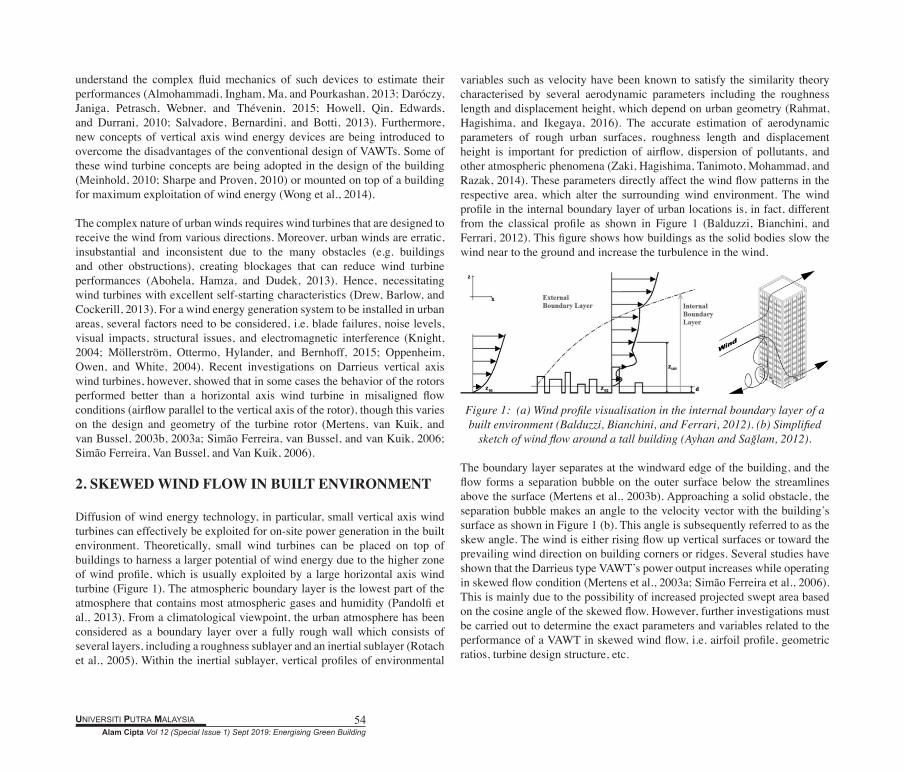
The lift and drag coefficient of an airfoil blade are the major parameters that determine its aerodynamic performance. These coefficients vary with every angle of attack (AOA) of the airfoil blade. The AOA is a term used in wind turbine design to describe the angle between the chord line of an airfoil and the oncoming wind flow. Lift coefficient, CL is the factor that contributes to the elevation of the blade (lift is always perpendicular to the wind flow). Drag coefficient, CD is used to quantify the drag, i.e. the resistance of an object in the air. These dimensionless units are expressed in the following equations:
where FL and FD is the lift and drag force respectively. Figure 2 shows the pressure distribution on an airfoil. The AOA of an airfoil controls the distribution of pressure above and below it. An airfoil at positive AOA develops negative pressure on its upper surface and positive pressure below it. The result of this pressure difference creates lift. Whereas, an airfoil at negative AOA develops negative pressure on the upper and lower surfaces of the airfoil, and positive pressure at its leading edge. This leads to the separation of flow at its trailing edge resulting in higher resistance or drag. Aerodynamic performance is fundamental for efficient rotor design. The lift-to-drag ratio is the amount of lift generated by the airfoil over the aerodynamic drag that it creates while moving through the air. A higher value of CL/CD ratio is more favourable as the higher lift with lower drag leads to a better performance of wind turbine. Traditionally, the airfoil is tested experimentally with tables correlating lift and drag at given AOA and Reynolds numbers. Wind turbine airfoil designs have been adapted from aircraft technologies with similar Reynolds numbers and section thicknesses that are suitable for conditions at the blade tip. However, due to the differences in operating conditions and
𝑃𝑃 =12𝜌𝜌𝜌𝜌𝑉𝑉
!×𝐶𝐶! (1)
𝐶𝐶! = 𝐹𝐹!/(0.5𝜌𝜌𝜌𝜌𝑉𝑉!) (2)
𝐶𝐶! = 𝐹𝐹!/(0.5𝜌𝜌𝜌𝜌𝑉𝑉!) (3)
mechanical loads, special considerations should be made for the design of wind turbine specific profiles and in low Reynolds number regime.
Figure 2: (a) An airfoil at positive angle of attack, (b) at negative angle of attack.
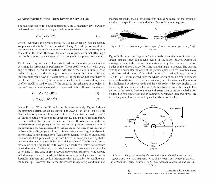
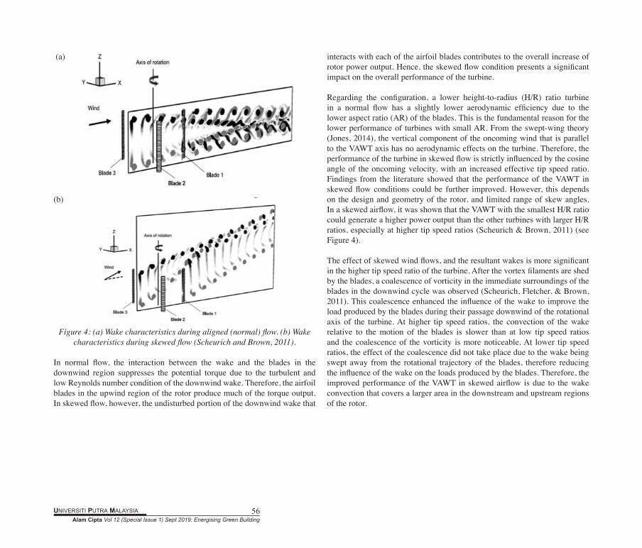
Figure 3 illustrates the diagram of a wind turbine configuration in the wind stream and the force components acting on the airfoil blades. During the rotating motion of the turbine, there exists varying forces along the airfoil blades as the blades change from one azimuth angle to another. The passing airfoils will encounter the wake of the previous passing airfoils as they move to the downwind region of the wind turbine rotor (azimuth angle between 180° to 360°). In an aligned flow, the whole length of each airfoil is exposed to the wake of the turbine in the downwind region of the rotor; see Figure 4(a). In misaligned flow, the convection of the wake follows the skew angles of the oncoming flow as shown in Figure 4(b), therefore allowing the undisturbed portion of the skewed flow to interact with some parts of the downwind airfoil blades. The resultant effect, and in comparison, between these two flows, are in the tangential force produced by each of the airfoil blades.
Figure 3: Diagram showing the wind direction, the definition of rotor azimuth angle, ψ and direction of positive normal and tangential forces,
as well as the relative positions of the rotor blades (Scheurich and Brown, 2011).
Alam Cipta Vol 12 (Special Issue 1) Sept 2019: Energising Green BuildingUNIVERSITI PUTRA MALAYSIA 56
(a)
(b)
Figure 4: (a) Wake characteristics during aligned (normal) flow. (b) Wake
characteristics during skewed flow (Scheurich and Brown, 2011).
In normal flow, the interaction between the wake and the blades in the downwind region suppresses the potential torque due to the turbulent and low Reynolds number condition of the downwind wake. Therefore, the airfoil blades in the upwind region of the rotor produce much of the torque output. In skewed flow, however, the undisturbed portion of the downwind wake that
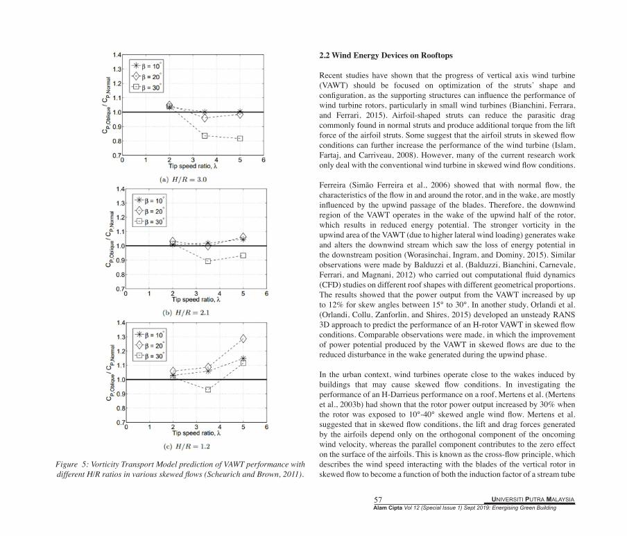
interacts with each of the airfoil blades contributes to the overall increase of rotor power output. Hence, the skewed flow condition presents a significant impact on the overall performance of the turbine. Regarding the configuration, a lower height-to-radius (H/R) ratio turbine in a normal flow has a slightly lower aerodynamic efficiency due to the lower aspect ratio (AR) of the blades. This is the fundamental reason for the lower performance of turbines with small AR. From the swept-wing theory (Jones, 2014), the vertical component of the oncoming wind that is parallel to the VAWT axis has no aerodynamic effects on the turbine. Therefore, the performance of the turbine in skewed flow is strictly influenced by the cosine angle of the oncoming velocity, with an increased effective tip speed ratio. Findings from the literature showed that the performance of the VAWT in skewed flow conditions could be further improved. However, this depends on the design and geometry of the rotor, and limited range of skew angles. In a skewed airflow, it was shown that the VAWT with the smallest H/R ratio could generate a higher power output than the other turbines with larger H/R ratios, especially at higher tip speed ratios (Scheurich & Brown, 2011) (see Figure 4).
The effect of skewed wind flows, and the resultant wakes is more significant in the higher tip speed ratio of the turbine. After the vortex filaments are shed by the blades, a coalescence of vorticity in the immediate surroundings of the blades in the downwind cycle was observed (Scheurich, Fletcher, & Brown, 2011). This coalescence enhanced the influence of the wake to improve the load produced by the blades during their passage downwind of the rotational axis of the turbine. At higher tip speed ratios, the convection of the wake relative to the motion of the blades is slower than at low tip speed ratios and the coalescence of the vorticity is more noticeable. At lower tip speed ratios, the effect of the coalescence did not take place due to the wake being swept away from the rotational trajectory of the blades, therefore reducing the influence of the wake on the loads produced by the blades. Therefore, the improved performance of the VAWT in skewed airflow is due to the wake convection that covers a larger area in the downstream and upstream regions of the rotor.
UNIVERSITI PUTRA MALAYSIA 57Alam Cipta Vol 12 (Special Issue 1) Sept 2019: Energising Green Building
Figure 5: Vorticity Transport Model prediction of VAWT performance with different H/R ratios in various skewed flows (Scheurich and Brown, 2011).
2.2 Wind Energy Devices on Rooftops
Recent studies have shown that the progress of vertical axis wind turbine (VAWT) should be focused on optimization of the struts’ shape and configuration, as the supporting structures can influence the performance of wind turbine rotors, particularly in small wind turbines (Bianchini, Ferrara, and Ferrari, 2015). Airfoil-shaped struts can reduce the parasitic drag commonly found in normal struts and produce additional torque from the lift force of the airfoil struts. Some suggest that the airfoil struts in skewed flow conditions can further increase the performance of the wind turbine (Islam, Fartaj, and Carriveau, 2008). However, many of the current research work only deal with the conventional wind turbine in skewed wind flow conditions.
Ferreira (Simão Ferreira et al., 2006) showed that with normal flow, the characteristics of the flow in and around the rotor, and in the wake, are mostly influenced by the upwind passage of the blades. Therefore, the downwind region of the VAWT operates in the wake of the upwind half of the rotor, which results in reduced energy potential. The stronger vorticity in the upwind area of the VAWT (due to higher lateral wind loading) generates wake and alters the downwind stream which saw the loss of energy potential in the downstream position (Worasinchai, Ingram, and Dominy, 2015). Similar observations were made by Balduzzi et al. (Balduzzi, Bianchini, Carnevale, Ferrari, and Magnani, 2012) who carried out computational fluid dynamics (CFD) studies on different roof shapes with different geometrical proportions. The results showed that the power output from the VAWT increased by up to 12% for skew angles between 15° to 30°. In another study, Orlandi et al. (Orlandi, Collu, Zanforlin, and Shires, 2015) developed an unsteady RANS 3D approach to predict the performance of an H-rotor VAWT in skewed flow conditions. Comparable observations were made, in which the improvement of power potential produced by the VAWT in skewed flows are due to the reduced disturbance in the wake generated during the upwind phase.
In the urban context, wind turbines operate close to the wakes induced by buildings that may cause skewed flow conditions. In investigating the performance of an H-Darrieus performance on a roof, Mertens et al. (Mertens et al., 2003b) had shown that the rotor power output increased by 30% when the rotor was exposed to 10°-40° skewed angle wind flow. Mertens et al. suggested that in skewed flow conditions, the lift and drag forces generated by the airfoils depend only on the orthogonal component of the oncoming wind velocity, whereas the parallel component contributes to the zero effect on the surface of the airfoils. This is known as the cross-flow principle, which describes the wind speed interacting with the blades of the vertical rotor in skewed flow to become a function of both the induction factor of a stream tube
Alam Cipta Vol 12 (Special Issue 1) Sept 2019: Energising Green BuildingUNIVERSITI PUTRA MALAYSIA 58
and the skew angle. Lee et al. (Lee, Tsao, Tzeng, and Lin, 2017) investigated the influence of the vertical wind and wind direction on the performance of a small VAWT on the rooftop of a building. Their study showed that the vertical wind coming off from the sides of the building greatly influence the power output of the VAWT, in which 90% of the power was generated when the vertical angle is less than or equal to 45°, and when the horizontal wind speed is between 5 m/s and 8 m/s.
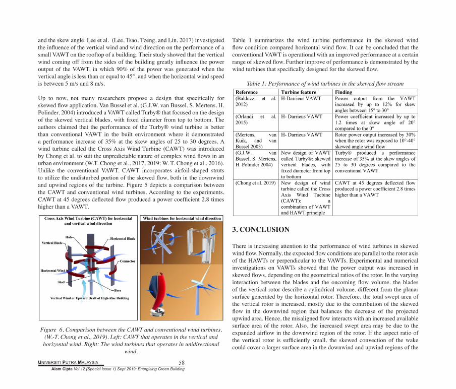
Up to now, not many researchers propose a design that specifically for skewed flow application. Van Bussel et al. (G.J.W. van Bussel, S. Mertens, H. Polinder, 2004) introduced a VAWT called Turby® that focused on the design of the skewed vertical blades, with fixed diameter from top to bottom. The authors claimed that the performance of the Turby® wind turbine is better than conventional VAWT in the built environment where it demonstrated a performance increase of 35% at the skew angles of 25 to 30 degrees. A wind turbine called the Cross Axis Wind Turbine (CAWT) was introduced by Chong et al. to suit the unpredictable nature of complex wind flows in an urban environment (W.T. Chong et al., 2017, 2019; W. T. Chong et al., 2016). Unlike the conventional VAWT, CAWT incorporates airfoil-shaped struts to utilize the undisturbed portion of the skewed flow, both in the downwind and upwind regions of the turbine. Figure 5 depicts a comparison between the CAWT and conventional wind turbines. According to the experiments, CAWT at 45 degrees deflected flow produced a power coefficient 2.8 times higher than a VAWT.
Figure 6. Comparison between the CAWT and conventional wind turbines.
(W.-T. Chong et al., 2019). Left: CAWT that operates in the vertical and horizontal wind. Right: The wind turbines that operates in unidirectional
wind.
Table 1 summarizes the wind turbine performance in the skewed wind flow condition compared horizontal wind flow. It can be concluded that the conventional VAWT is operational with an improved performance at a certain range of skewed flow. Further improve of performance is demonstrated by the wind turbines that specifically designed for the skewed flow.
Table 1: Performance of wind turbines in the skewed flow stream
3. CONCLUSION
There is increasing attention to the performance of wind turbines in skewed wind flow. Normally, the expected flow conditions are parallel to the rotor axis of the HAWTs or perpendicular to the VAWTs. Experimental and numerical investigations on VAWTs showed that the power output was increased in skewed flows, depending on the geometrical ratios of the rotor. In the varying interaction between the blades and the oncoming flow volume, the blades of the vertical rotor describe a cylindrical volume, different from the planar surface generated by the horizontal rotor. Therefore, the total swept area of the vertical rotor is increased, mostly due to the contribution of the skewed flow in the downwind region that balances the decrease of the projected upwind area. Hence, the misaligned flow interacts with an increased available surface area of the rotor. Also, the increased swept area may be due to the expanded airflow in the downwind region of the rotor. If the aspect ratio of the vertical rotor is sufficiently small, the skewed convection of the wake could cover a larger surface area in the downwind and upwind regions of the
Reference Turbine feature Finding (Balduzzi et al. 2012)
H-Darrieus VAWT Power output from the VAWT increased by up to 12% for skew angles between 15° to 30°
(Orlandi et al. 2015)
H- Darrieus VAWT Power coefficient increased by up to 1.2 times at skew angle of 20° compared to the 0°
(Mertens, van Kuik, and van Bussel 2003)
H- Darrieus VAWT Rotor power output increased by 30% when the rotor was exposed to 10°-40° skewed angle wind flow
(G.J.W. van Bussel, S. Mertens, H. Polinder 2004)
New design of VAWT called Turby®: skewed vertical blades, with fixed diameter from top to bottom
Turby® produced a performance increase of 35% at the skew angles of 25 to 30 degrees compared to the conventional VAWT.
(Chong et al. 2019) New design of wind turbine called the Cross Axis Wind Tuebine (CAWT): a combination of VAWT and HAWT principle
CAWT at 45 degrees deflected flow produced a power coefficient 2.8 times higher than a VAWT
UNIVERSITI PUTRA MALAYSIA 59Alam Cipta Vol 12 (Special Issue 1) Sept 2019: Energising Green Building
rotor. Therefore, the interaction between the skewed airflow and the blades of the vertical rotor could potentially generate more lift, hence producing higher torque and better power output. The study has shown that the Darrieus vertical axis wind turbine has the potential for the built environment due to the effect of the skewed wind flows. Evidently, the remarkable outcome of many of the studies has illustrated that the VAWT can generate a higher power output in skewed flow, compared to VAWT in normal flow. To optimize the siting of VAWT on top of rooftops, it is recommended that wind profile studies must be carried out to determine the best placement of VAWT in skewed airflows. This is to ensure that the performance of the VAWT can be maximized, and therefore the diffusion of wind energy technology in the urban environment can be more efficient.
ACKNOWLEDGEMENT
The authors acknowledge the financial supports from the Universiti Malaysia Sabah (UMS) Centre for Research and Innovation (PPI) under the research grant scheme (SLB0174-2018) and Universiti Kebangsaan Malaysia (UKM) under the Young Researcher Encouragement Grant, UKM (GGPM-2017-094).
REFERENCES
Abohela, I., Hamza, N., & Dudek, S. (2013). Effect of roof shape, wind direction, building height and urban configuration on the energy yield and positioning of roof mounted wind turbines. Renewable Energy, 50, 1106–1118. https://doi.org/10.1016/j.renene.2012.08.068
Almohammadi, K. M., Ingham, D. B., Ma, L., & Pourkashan, M. (2013). Computational fluid dynamics (CFD) mesh independency techniques for a straight blade vertical axis wind turbine. Energy, 58, 483–493.
Amet, E., Maître, T., Pellone, C., & Achard, J.-L. (2009). 2D Numerical Simulations of Blade-Vortex Interaction in a Darrieus Turbine. Journal of Fluids Engineering, 131(11), 111103–111115. Retrieved from http://dx.doi.org/10.1115/1.4000258
Ayhan, D., & Sağlam, Ş. (2012). A technical review of building-mounted wind power systems and a sample simulation model. Renewable and Sustainable Energy Reviews, 16(1), 1040–1049.
Balduzzi, F., Bianchini, A., Carnevale, E. A., Ferrari, L., & Magnani, S. (2012). Feasibility analysis of a Darrieus vertical-axis wind turbine installation in the rooftop of a building. Applied Energy, 97, 921–929.
Balduzzi, F., Bianchini, A., & Ferrari, L. (2012). Microeolic turbines in the built environment: influence of the installation site on the potential energy
yield. Renewable Energy, 45, 163–174.Bianchini, A., Ferrara, G., & Ferrari, L. (2015). Pitch optimization in small-
size darrieus wind turbines. In Energy Procedia (Vol. 81, pp. 122–132). https://doi.org/10.1016/j.egypro.2015.12.067
Brahimi, M. T., Allet, A., & Paraschivoiu, I. (1995). Aerodynamic Analysis Models for Vertical-Axis Wind Turbines. International Journal of Rotating Machinery, 2(1), 15–21.
Chong, W.-T., Muzammil, W. K., Ong, H.-C., Sopian, K., Gwani, M., Fazlizan, A., & Poh, S.-C. (2019). Performance analysis of the deflector integrated cross axis wind turbine. Renewable Energy, 138, 675–690. https://doi.org/10.1016/J.RENENE.2019.02.005
Chong, W.-T., Muzammil, W. K., Wong, K.-H., Wang, C.-T., Gwani, M., Chu, Y.-J., & Poh, S.-C. (2017). Cross axis wind turbine: Pushing the limit of wind turbine technology with complementary design. Applied Energy, In Press. https://doi.org/10.1016/j.apenergy.2017.06.099
Chong, W. T., Muzammil, W. K., Gwani, M., Wong, K. H., Fazlizan, A., Wang, C. T., & Poh, S. C. (2016). The development and testing of a novel cross axis wind turbine. In AIP Conference Proceedings (Vol. 1737). https://doi.org/10.1063/1.4949283
Daróczy, L., Janiga, G., Petrasch, K., Webner, M., & Thévenin, D. (2015). Comparative analysis of turbulence models for the aerodynamic simulation of H-Darrieus rotors. Energy, 90, 680–690.
Drew, D. R., Barlow, J. F., & Cockerill, T. T. (2013). Estimating the potential yield of small wind turbines in urban areas: A case study for Greater London, UK. Journal of Wind Engineering and Industrial Aerodynamics, 115, 104–111. https://doi.org/10.1016/j.jweia.2013.01.007
Fazlizan, A., Chong, W. T., Yip, S. Y., Hew, W. P., & Poh, S. C. (2015). Design and experimental analysis of an exhaust air energy recovery wind turbine generator. Energies, 8(7), 6566–6584. https://doi.org/10.3390/en8076566
G.J.W. van Bussel, S. Mertens, H. Polinder, H. F. A. S. (2004). TURBY ® : concept and realisation of a small VAWT for the built environment. In EAWE/EWEA. https://doi.org/10.1016/j.cma.2014.10.049
Howell, R., Qin, N., Edwards, J., & Durrani, N. (2010). Wind tunnel and numerical study of a small vertical axis wind turbine. Renewable Energy, 35(2), 412–422. https://doi.org/10.1016/j.renene.2009.07.025
Islam, M., Fartaj, A., & Carriveau, R. (2008). Analysis of the Design Parameters related to a Fixed-pitch Straight-Bladed Vertical Axis Wind Turbine. Wind Engineering, 32(5), 491–507. https://doi.org/10.1260/030952408786411903
Jones, R. T. (2014). Wing Theory (2014th ed.). Oxford, United Kingdom: Princeton University Press.
Knight, J. (2004). Breezing into town. Nature. https://doi.org/10.1038/430012aLee, K.-Y., Tsao, S.-H., Tzeng, C.-W., & Lin, H.-J. (2017). Influence of the
Alam Cipta Vol 12 (Special Issue 1) Sept 2019: Energising Green BuildingUNIVERSITI PUTRA MALAYSIA 60
vertical wind and wind direction on the power output of a small vertical-axis wind turbine installed on the rooftop of a building. Applied Energy, In Press. https://doi.org/10.1016/J.APENERGY.2017.08.185
Meinhold, B. (2010). Chicago parking gar age harvests energy from windy city gusts. Retrieved from https://inhabitat.com/chicago-parking-garage-harvests-energy-from-windy-city-gusts/
Mertens, S., van Kuik, G., & van Bussel, G. (2003a). Performance of a High Tip Speed Ratio H-Darrieus in the Skewed Flow on a Roof. Retrieved from http://dx.doi.org/10.1115/WIND2003-523
Mertens, S., van Kuik, G., & van Bussel, G. (2003b). Performance of an H-Darrieus in the Skewed Flow on a Roof. Journal of Solar Energy Engineering, 125(4), 433. https://doi.org/10.1115/1.1629309
Möllerström, E., Ottermo, F., Hylander, J., & Bernhoff, H. (2015). Noise Emission of a 200 kW Vertical Axis Wind Turbine. Energies, 9(1), 19. https://doi.org/10.3390/en9010019
Oppenheim, D., Owen, C., & White, G. (2004). Outside the square: Integrating wind into urban environments. Refocus. https://doi.org/10.1016/S1471-0846(04)00141-6
Orlandi, A., Collu, M., Zanforlin, S., & Shires, A. (2015). 3D URANS analysis of a vertical axis wind turbine in skewed flows. Journal of Wind Engineering and Industrial Aerodynamics, 147, 77–84. https://doi.org/10.1016/j.jweia.2015.09.010
Pandolfi, M., Martucci, G., Querol, X., Alastuey, A., Wilsenack, F., Frey, S., … Dall’Osto, M. (2013). Continuous atmospheric boundary layer observations in the coastal urban area of Barcelona during SAPUSS. Atmospheric Chemistry and Physics, 13(9), 4983–4996.
Rahmat, N. A., Hagishima, A., & Ikegaya, N. (2016). An experimental study on aerodynamic interaction between a boundary layer generated by a smooth and rough wall and a wake behind a spire. Engineering Sciences Reports, Kyushu University, 37(2), 19–26.
Rotach, M. W., Vogt, R., Bernhofer, C., Batchvarova, E., Christen, A., Clappier, A., … Mayer, H. (2005). BUBBLE–an urban boundary layer meteorology project. Theoretical and Applied Climatology, 81(3–4), 231–261.
Salvadore, F., Bernardini, M., & Botti, M. (2013). GPU accelerated flow solver for direct numerical simulation of turbulent flows. Journal of Computational Physics, 235, 129–142. https://doi.org/10.1016/j.jcp.2012.10.012
Scheurich, F., & Brown, R. E. (2011). Vertical-axis wind turbines in oblique flow: Sensitivity to rotor geometry. In European Wind Energy Conference and Exhibition 2011, EWEC 2011 (pp. 222–225). Retrieved from http://www.scopus.com/inward/record.url?eid=2-s2.0-84870187450&partnerID=40&md5=a2eb646d6bf82125ca60b5f86b71e9e6
Scheurich, F., Fletcher, T. M., & Brown, R. E. (2011). Effect of blade geometry on the aerodynamic loads produced by vertical-axis wind turbines. In Proceedings of the Institution of Mechanical Engineers, Part A: Journal of Power and Energy (Vol. 225, pp. 327–341). https://doi.org/10.1177/2041296710394248
Sharpe, T., & Proven, G. (2010). Crossflex: Concept and early development of a true building integrated wind turbine. Energy and Buildings, 42(12), 2365–2375. https://doi.org/10.1016/j.enbuild.2010.07.032
Simão Ferreira, C. J., van Bussel, G. J. W., & van Kuik, G. A. M. (2006). Wind Tunnel Hotwire Measurements, Flow Visualization and Thrust Measurement of a VAWT in Skew. Journal of Solar Energy Engineering, 128(4), 487. https://doi.org/10.1115/1.2349550
Simão Ferreira, C. J., Van Bussel, G., & Van Kuik, G. (2006). An analytical method to predict the variation in performance of a H-Darrieus in skewed flow and its experimental validation. In European Wind Energy Conference and Exhibition 2006, EWEC 2006 (Vol. 2, pp. 988–993). Retrieved from http://www.scopus.com/inward/record.url?eid=2-s2.0-84876547792&partnerID=40&md5=25505d32fc6d099b871b809dc4e206fb
Simão Ferreira, C. J., van Zuijlen, A., Bijl, H., van Bussel, G., & van Kuik, G. (2010). Simulating dynamic stall in a two-dimensional vertical-axis wind turbine: verification and validation with particle image velocimetry data. Wind Energy, 13(1), 1–17. https://doi.org/10.1002/we.330
Wagner, S., Bareiß, R., & Guidati, G. (1996). Wind Turbine Noise. Stuttgart, Germany: Springer.
Wong, K. H., Chong, W. T., Yap, H. T., Fazlizan, A., Omar, W. Z. W., Poh, S. C., & Hsiao, F. B. (2014). The design and flow simulation of a power-augmented shroud for urban wind turbine system. In Energy Procedia (Vol. 61, pp. 1275–1278). https://doi.org/10.1016/j.egypro.2014.11.1080
Worasinchai, S., Ingram, G. L., & Dominy, R. G. (2015). The Physics of H-Darrieus Turbine Starting Behavior. Journal of Engineering for Gas Turbines and Power, 138(6), 062605. https://doi.org/10.1115/1.4031870
Zaki, S. A., Hagishima, A., Tanimoto, J., Mohammad, A. F., & Razak, A. A. (2014). Estimation of aerodynamic parameters of urban building arrays using wind tunnel measurements. Journal of Engineering Science and Technology, 9, 176–190.